ORIGINAL ARTICLE
Design and Experiment of Triangular
Prism Mast with Tape-Spring Hyperelastic
Hinges
Hui Yang
1, Hong-Wei Guo
2*, Yan Wang
3, Rong-Qiang Liu
2and Meng Li
4Abstract
Because of the limited space of the launch rockets, deployable mechanisms are always used to solve the phenom-enon. One dimensional deployable mast can deploy and support antenna, solar sail and space optical camera. Tape-spring hyperelastic hinges can be folded and extended into a rod like configuration. It utilizes the strain energy to realize self-deploying and drive the other structures. One kind of triangular prism mast with tape-spring hyper-elastic hinges is proposed and developed. Stretching and compression stiffness theoretical model are established with considering the tape-spring hyperelastic hinges based on static theory. The finite element model of ten-module triangular prism mast is set up by ABAQUS with the tape-spring hyperelastic hinge and parameter study is performed to investigate the influence of thickness, section angle and radius. Two-module TPM is processed and tested the compression stiffness by the laser displacement sensor, deploying repeat accuracy by the high speed camera, modal shape and fundamental frequency at cantilever position by LMS multi-channel vibration test and analysis system, which are used to verify precision of the theoretical and finite element models of ten-module triangular prism mast with the tape-spring hyperelastic hinges. This research proposes an innovative one dimensional triangular prism with tape-spring hyperelastic hinge which has great application value to the space deployable mechanisms.
Keywords: Deployable mechanism, Triangular prism mast, Tape-spring hyper-elastic hinges, Static analysis, Modal experiment
© The Author(s) 2018. This article is distributed under the terms of the Creative Commons Attribution 4.0 International License (http://creativecommons.org/licenses/by/4.0/), which permits unrestricted use, distribution, and reproduction in any medium, provided you give appropriate credit to the original author(s) and the source, provide a link to the Creative Commons license, and indicate if changes were made.
1 Introduction
Conventional articulated truss structures are composed of mechanical hinges which can meet accuracy and stiff-ness requires of space mission. But those structures have some disadvantages, such as large weight, high friction and energy-wasting features. Tape-spring hyperelastic (TSH) hinges, which are folded elastically can self-deploy by releasing stored strain energy, which consist of a fewer component parts, can be manufactured conveni-ently [1, 2]. Flexible hinges have several advantages for space applications, including a low mass-to-deployed-stiffness ratio, cost, and self-latch [3]. With the increasing demand, flexible hinges have been widely used as folding
and deployment mechanisms in deployable structures, such as synthetic aperture radars (SARs) [4–6], solar arrays and antenna booms. Tape-spring hinges have been used in the Japanese Mars orbiter PLANT-B for bar-like deployment structures of the thermal plasma analyzer [7–9].
The U.S. Air Force Research Laboratory (AFRL) [10] used TSH hinge in the main truss’s folding longeron elements, which provided considerable snap-through force to drive and lock the main truss. Imperial Col-lege London Santer [11] proposed a concertina-folded magnetometer boom with TSH hinges for CubeSat use. Watt et al. [12] proposed a TSH hinge with two sets of wheels held together by wires wrapped around them, and deploying impact is reduced for the added damp. The Mars Advanced Radar Express spacecraft [13, 14] con-sisted of two 20 m dipoles and a 7 m monopole which were slotted at certain intervals to stow them in a much
Open Access
*Correspondence: [email protected]
2 China State Key Laboratory of Robotics and System, Harbin Institute of Technology, Harbin 150001, China
small size. Silver et al. [15] proposed an integral folding hinge to deploy camera and investigated axial loading, bending induced buckling response. Schioler et al. and Seffen et al. [16, 17] analyzed buckling properties of sin-gle layer TSH hinge based on Timoshenko theory. Seffen et al. [18] got sample points by finite element method and obtained fitting nonlinear mechanical models by single value decomposition method of TSH hinge. Guan et al. [19, 20] designed a TSH hinge for solar sail and investi-gated its buckling properties by finite element method. Bai et al. [21], Yan et al. [22], Wang et al. [23] investi-gated geometrical and mechanical properties of ultra-thin-walled lenticular collapsible composite tube in fold deformation. Yang et al. [24, 25] optimized the geomet-ric parameters of TSH hinge to improve driving moment and reduce deploying impact, and established two differ-ent theoretical models to analyze the stability of deploy-ment status for the TSH hinges. However, there are still some engineering problems for the TSH hinge applying to a deployable mechanism.
This paper proposed a new ten-module triangu-lar prism mast (TPM) with TSH hinges. Static bend-ing stiffness and compression stiffness theoretical models are established. The compression stiffness tests
are performed to verify the accuracy of the static theo-retical models of the TPM. Finite element model of ten-module TPM are establish by ABAQUS and geometrical parameter study are analyzed for bending and twisted modal frequencies. Two-module TPM is developed to test the fundamental frequencies and related modal shapes which are used to verify the accuracy of the ten-module TPM (Additional file 1).
2 Design and Static Analysis
2.1 Structures Design
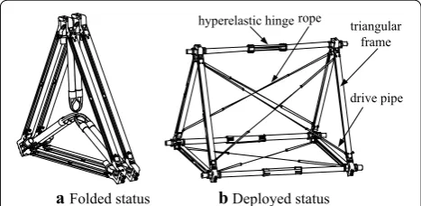
One module TPM with tape-spring hinges is shown in Figure 1. Adjacent two-module is connected by trian-gular frame. The length of triantrian-gular frame is 469 mm, stowed and deployed longitudinal lengths of ten-module prism mast are 475.2 mm and 5278 mm respectively. All components except standard parts are manufactured by duralumin 2A12. Each modulus TPM with TSH hinge contains three longitudinal links and two triangular frames. The TSH hinges are used to drive and lock TPM. Lateral area of each modulus has a series of flexible Kev-lar rope with tensile force 30 N which ensures high stiff-ness of the deployed prism mast and reduces deploying impact. There is one resin-based carbon fiber drive pipe one each end of the tensile lock which prevent involve-ment during deploying process.
The TSH hinge folded with 180°, the two triangular frame close to each other, and three longitudinal links folded between the two triangular frames when the mast stowed. The tape-spring drive the mast to deploy. After deploying, the TSH hinge restore original shape, the Kevlar ropes tensile and the TPM was rigidified to a structure.
2.2 Static Analysis
Bending stiffness analysis has been analyzed in Ref. [8]. Thus, stretching stiffness and compression stiffness will be derived in this paper.
2.2.1 Stretching Stiffness
Axial force F0 is applied on each point A, B and C. Cir-cumcircle radius of cross section is R1=lb
√
3. Stretch force diagram is shown as Figure 2.
By resolving the forces in the x-direction at point A, the equation is obtained as follows.
where Fl is axial force of longitudinal link, Fr0 is initial pretension of the rope, lb is the cross link length, β0 is the angle between line GD and line ED.
When the TPM is under stretching, deformation of longitudinal link and diagonal rope has following related equation based on geometric deformation condition.
(1)
2Fr0sinβ0+Fl=F0,
hyperelastic hinge triangular frame
drive pipe rope
aFolded status bDeployed status
Figure 1 One modulus TPM with Hyperelastic hinges
x
y
z A
C B
D E
G
F0
F0
α0
β0
where δri is rope deformation in each modulus, δli is lon-gitudinal stretch deformation of each modulus, lr is rope length, Fr is the force in rope, Er is the material Young modulus for rope, Ar is cross section area of the rope, l1 is the length of longitudinal rigid link, l2 is the length of the TSH hinge, Fl is the force in the longitudinal link, E1 is the material Young modulus for longitudinal link, A1 is the cross-section area of the longitudinal link, n1 is the number of the tape spring, a11 is the unit stretching stiff-ness of the TSH hinge.
Stretch deformation δl of the TPM is
where n2 is the module number of the TPM, EA is the stretching stiffness of the TPM.
Simultaneous Eqs. (1), (2) and (3), stretching stiffness of the TPM is obtained as follows:
If the TPM has no rape, the stretching stiffness is rear-ranged as follows:
2.2.2 Compression Stiffness
One end of the TPM is fixed and a compressive force 3F0 is applied on the other end. Due to initial tension Fr0 of rope initial deformation is δr0=Fr0lr/(ErAr), which leads to a critical compress value 3F0′ on the end. Based on the geometric deformation conditions longitudinal link deformation of each module is written as follows:
When compressive force is applied at point A, equilib-rium equation is gotten as follows:
(2a)
δir =δ
i lsinβ0,
(2b)
δir = Frlr
ErAr
,
(2c)
δil =
2Fll1
E1A1+ Fll2
n1a11,
(3a) δl=
n2·3F0(2l1+l2)
EA ,
(3b)
δl=n2δil,
(4) EA=6ErArsin3β0+
3(2l1+l2)
2l1
E1A1 +
l2(1−ν2)
n1Et
.
EA= 3(2l1+l2)
2l1 E1A1 +
l2(1−ν2) n1Et
.
(5)
δil =
δr0
sinβ0 .
(6)
−2Frsinβ0+Fl=F0.
Simultaneous Eq. (2c), Eq. (5) and Eq. (6), critical unloaded compressive force is expressed as follows:
If axial compressive force is no less than the critical unloaded compressive force, unloaded compressive stiff-ness equals to sum total compression stiffstiff-ness of longitu-dinal rigid links and hyperelastic tape-spring hinges, that is
If axial compressive force is more than the critical unloaded compressive force, the total deformation of the rope is
where δr′ is deformation of the rope with only axial com-press force, δr0 is deformation of the rope under initial pretension force.
Single module longitudinal link and rope deformation meets the geometric deformation conditions. When 3F0 is lower than F′, simultaneous Eq. (2), Eq. (3), Eq. (6) and Eq. (9) equivalent compression stiffness of the TPM is
It is found that when 3F0 is more than F′ the compres-sion stiffness is related to the comprescompres-sion stiffness of the longitudinal link and the TSH hinges; when 3F0 is lower than F′, the compression stiffness changed with axial load. If the end compress load 3F0 is much small, that is
The compression stiffness can be written as follows
The compression stiffness is only related to the rope stiffness ErAr and initial angle β0.
(7) F′= 3Fr0lr
ErArsinβ0
2l 1 E1A1 +
l2 n1a11
.
(8)
EA= 3(2l1+l2)
2l1 E1A1 +
l2 n1a11
.
(9a)
δr =δr0−δr′,
(9b)
δ′ r =
F′ rlr
ErAr
,
(10) EA=6ErArsin3β0+3
1−2Fr0sinβ0 F′
l
(2l1+l2) 2l1
E1A1+ l2(1−ν2)
n1Et
.
(11) 3F0=12F0sin3β0·
2l1
E1A1+
l2(1−ν2)
n1Et
·
ErAr
lr
.
3 Deploying State Modal Analysis
3.1 Modal Analysis
Due to nonlinear characteristics of the TSH hinge modal analysis of the TPM is performed by ABAQUS. In finite element model x-axis is along direction of transverse link, y-axis is along longitudinal link and z-axis points from section center of transverse links to point of the other two transverse links. Materials of the TSH hinge, rigid link, transverse link and rope are Ni36CrTiAl, stain-less steel, aluminum alloy and Kevlar respectively. Longi-tudinal link, transverse link and the TSH hinge are set up with four nodes that are fully integrated to reduce shell elements (S4R). Rope is modeled by two nodes and three dimensional elements (T3D2). Weld is defined to model connection between ropes and transverse links. Refer-ence point (RP) is established at each joint which are given mass and inertial properties. Multi-point coupling is applied to model the connection of transverse links. The joint hinges are modeled by defining Hinge connec-tion. Contact of tape springs are modeled by defining Tie constraint.
Six reference points at the root of the TPM restrain three translational Degree of Freedoms (DOFs) and the TPM is in the state of cantilever. Firstly, the TPM is performed on static analysis with 30 N pretension force and deformation is got. Then, modal analysis is done by subspace method with rope prestress deformation. Total length for ten-module TPM is 5.26 m. Figure 3 shows the FEM of the ten-module TPM with TSH hinges.
The five order modal shapes of ten modules TPM with TSH hinge are shown in Figure 4. The five order mode frequencies and mode shape description are listed in Table 1.
3.2 Parameter Study
Compared to conventional rigid deployable mechanism the TSH hinge introduces flexible influence. Thus, it is necessary to analyze the effect of geometric parameters, such as thickness t, cross-section radius R, center angle
φ and separation distance s, to mode frequency and pro-pose method of increasing stiffness. Table 2 lists frequen-cies of ten-module TPM under different thickness. It is shown that bend frequency increases 3.695%–11.84% and twist frequency increases 0.186%–0.221% when the thickness changes from 0.12 mm to 0.14 mm.
Table 3 lists ten-module mast frequencies under differ-ent tape cdiffer-entral angles. It can be seen that the bend fre-quency increases by 3.654%–6.156% and twist frefre-quency increases by 0.393%–0.434% when the central angle changes from 80° to 100°.
Frequencies of the ten-module TPM under differ-ent radiuses are listed in Table 4. It can be seen that bend frequencies increase by 2.674%–5.343% and twist
Figure 3 Finite element model of TPM with TSH hinges
Figure 4 Five order modal shapes of the ten-module TPM with the TSH hinges
Table 1 Five order mode frequencies and mode shape description of the ten-module TPM with TSH hinges
Order 1 2 3 4 5
Frequency (Hz) 2.561 4.243 9.770 12.671 19.557 Model shape Bend Twist Bend Twist Bend
Table 2 Frequencies of ten-module TPM under different thicknesses
Frequency (Hz) Thickness t (mm) Variable quantity δ (%) 0.12 0.16 0.20
fB1 2.5699 2.7468 2.8742 − 11.84
fB2 9.7959 10.124 10.361 − 5.769
fB3 19.593 20.018 20.317 − 3.695
fT1 4.2444 4.2488 4.2523 − 0.186
frequencies increase by 0.372%–0.41% when radius change from 18 mm to 22 mm.
Frequencies of ten-module TPM under different sepa-rations are listed in Table 5. It can be seen that bend frequencies decrease by 0.0428%–0.0919% and twist fre-quencies increase by 0.134%–0.141% when the separation changes from 16 mm to 20 mm.
It can be concluded that geometric parameters have greater influence on bend stiffness than twist stiffness. Sensitivity of the geometric parameter is from large to small as follows: thickness, central angle, radius and separation. What’s more, front three parameters have enhanced effect on bend stiffness and the last one has induced effect.
4 Experiment Investigation
4.1 Two‑module TPM
To validate the precision of static stiffness theoretical model, two units triangular prism mast is developed. Fig-ure 5 is folding and deployment configurations of trian-gular prism mast with hyperelastic hinges.
Two adjacent units triangular prism mast are closed to each other by locating pins and fastened to a work holder by a rope when it is folded. At this time, the longitudinal links are stowed into the prism frames and tension ropes are located to grooves. After releasing the tension ropes, Table 3 Frequencies of ten-module TPM under different tape central angles
Frequency (Hz) Angle φ ()° Variable quan‑ tity δ (%)
80 90 100
fB1 2.5699 2.6553 2.7281 − 6.156
fB2 9.7959 10.022 10.208 − 4.207
fB3 19.593 20.002 20.309 − 3.654
fT1 4.2444 4.253 4.2611 − 0.393
fT2 12.674 12.702 12.729 − 0.434
Table 4 Frequencies of ten-module TPM under different radiuses
Frequency
(Hz) Radius R (mm) Variable quantity δ (%)
18 20 22
fB1 2.5699 2.6433 2.7072 − 5.343
fB2 9.7959 9.9694 10.118 − 3.288
fB3 19.593 19.889 20.117 − 2.674
fT1 4.2444 4.2525 4.2602 − 0.372
fT2 12.674 12.701 12.726 − 0.41
Table 5 Frequencies of ten-module TPM under different separations
Frequency
(Hz) Separation se (mm) Variable quantity δ (%)
16 18 20
fB1 2.5699 2.5688 2.5688 0.0428
fB2 9.7959 9.7866 9.7869 0.0919
fB3 19.593 19.582 19.583 0.051
fT1 4.2444 4.2468 4.2504 − 0.141
fT2 12.674 12.681 12.691 − 0.134
Figure 5 Folded and deployed states of TPM with TSH hinges
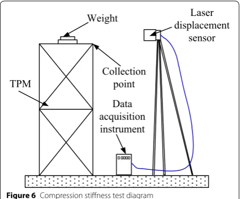
Weight displacementLaser
sensor
Collection point Data acquisition instrument TPM
Figure 6 Compression stiffness test diagram
Table 6 Compress load and displacement for the two-modulus TPM
Load (N) 100 200 300 400 500
the triangular prism mast is deploying by the driving of the TSH hinges. Spherical wheels support the mast to reduce the influence of gravity.
4.2 Compression Stiffness Test
Figure 6 is compression stiffness test diagram of the TPM. Weights are applied at the end of the TPM for 10 kg at each time. Compress load and displacement for the two-modulus TPM are listed in Table 6.
Figure 7 Deploying configuration for the two-modulus TPM
1st 2nd 3rd 4th 5th
0 1.0 2.0 3.0
0 0.2 0.4 0.6 0.8 1.0 1.2
Longitudinal displacement /m
Time /s 4.0
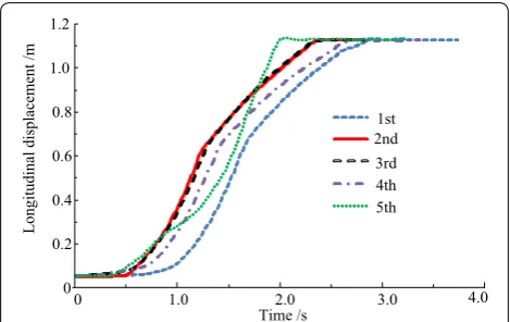
Figure 8 Longitudinal displacement–time relationship for five times deploying processes
Table 7 Longitudinal displacement for five times deploy-ment
Number 1 2 3 4 5
It can be calculated that experimental compression stiffness is 2.324 × 10⁶ N/m and theoretical value is 2.167 × 10⁶ N/m. Relative error between the experimen-tal and theoretical value is 7.08%. The main reason for the phenomenon is that equivalent stiffness of the TSH hinges is much smaller, contact stiffness between the tape springs should be considered.
4.3 Deploying Repeat Accuracy Test
Figure 7 shows deploying configuration for the two modulus TPM. High-speed camera is employed to cap-ture deploying process of the TPM. Spherical hinges and elastic rope are used to eliminate the effect of weight and friction. Figure 8 shows longitudinal displacement-time relationship for five times deploying processes. Table 7 lists compress load and displacement for the two-modu-lus TPM. Acceleration sensor Exciting hammer Data processing display Dynamic signal acquisition system a1 a2 a3 b1 b2 b3 X Y Z y1 z1 x1 y2 z2 x2 y3 z3 x3
a Test apparatus bGeometry diagram
Figure 9 Test apparatus and geometry diagram of cantilever posi-tion
0 20 40 60 80 100
0 0.2 0.4 0.6 0.8 1.0 f/Hz Amplitude ˄ g/N ˅ a:1:x b:1:x
0 20 40 60 80 100
0 0.04 0.08 0.12 0.16 a:1:y b:1:y f/Hz Amplitude ˄ g/ N ˅
0 20 40 60 80 100 0 0.1 0.2 0.3 0.4 a:1:z b:1:z f/Hz Amplitude ˄ g/ N ˅
st –Xresponse st –Yresponse st –Zresponse
0 20 40 60 80 100
0 0.4 0.8 1.2 1.6 a:2:x b:2:x f/Hz Amplitude ˄ g/ N ˅
0 20 40 60 80 100
0 0.02 0.04 0.06 0.08 a:2:y b:2:y f/Hz Amplitude ˄ g/N ˅
0 20 40 60 80 100
0 0.1 0.2 0.3 0.4 a:2:z b:2:z f/Hz Amplitude ˄ g/ N ˅
nd –Xresponse nd –Yresponse nd –Zresponse
0 20 40 60 80 100
0 0.5 1.5 2.5 a:3:x b:3:x f/Hz Amplitude ˄ g/ N ˅
0 20 40 60 80 100
0 0.2 0.4 0.6 0.8 a:3:y b:3:y f/Hz Amplitude ˄ g/ N ˅
0 20 40 60 80 100
0 1 2 3 4 a:3:z b:3:z f/Hz Amplitude ˄ g/N ˅
rd –Xresponse rd –Yresponse
a 1 b 1 c 1
d 2 e 2 f 2
g 3 h 3 i 3rd –Zresponse
Based on longitudinal displacement for five times deploying test standard deviation of the experimental value is 1.688 mm. Thus, deploying repeat accuracy is 1.688 mm.
4.4 Modal Analysis of Cantilever Position
LMS multi-channel vibration test and analysis system is employed to measure fundamental frequencies and mode shapes which consists of exciting hammer, acceleration sensor which can test three directional accelerations, dynamic signal acquisition system and data processor. The longitudinal direction of the TPM is set as x-axis, outer normal direction of cross section is set as y-axis and vertical downward direction is set as z-axis which is selected as force hammer stimulating direction. The measurements of three acceleration sensors, which are located at three nodes on the crossbeam, are divided into three groups. Then, integral modal superposition is car-ried out. The exciting point is set at one end of the cross-beam. Test apparatus and geometry diagram of cantilever position are shown in Figure 9. Three vertexes on the bot-tom are constrained points. Alphabets a and b stand for the order of two times measurement. Location of point
b3 is closest to the exciting point. Vibration test curves of six nodes for two-module TPM at cantilever position are shown in Figure 10. Modal shapes for the TPM at cantile-ver position are shown in Figure 11. Modal test results for the two-modulus TPM at cantilever position are listed in Table 8. It can be seen that acceleration sensor at point
b3 has a larger response at initial phase; response curves of two group acceleration sensors are concentrated on
a
1st, bend
nd, torsion
rd, bend
th, torsion
b
2
c3
d
4
e5th, bend
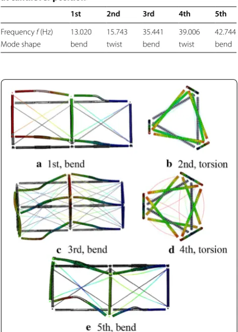
Figure 11 Modal shapes for the TPM at cantilever position
Table 8 Modal test results for the two-modulus TPM at cantilever position
1st 2nd 3rd 4th 5th
Frequency f (Hz) 13.020 15.743 35.441 39.006 42.744 Mode shape bend twist bend twist bend
middle- and low frequency. The first order frequency of the TPM at cantilever position is 13.02 Hz and corre-sponding mode shape is bending.
Then, modal analysis of the two-module TPM at can-tilever position and the modeling method is identical to the ten-module TPM by ABAQUS. Modal shape simula-tion results for the two-module TPM at cantilever posi-tion are shown in Figure 12.
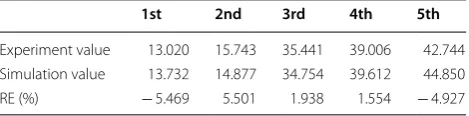
The model with black lines is undeformed configura-tion and the model with colored lines is deformed config-uration. Comparison between modal test and simulation results for the two-modulus TPM at cantilever position is listed in Table 9. It can be seen that the mode shapes between simulated and experimental results are consist-ent compared to Figures 11, 12 and Table 9. The relative errors between simulated and experimental results for frequencies are no more than 5.501%. It indicates that the finite element model for the ten-module TPM is accurate.
5 Conclusions
Structure design and deploying modal analysis of the ten-modulus TPM are performed. The two-ten-modulus TPM is processed and its mechanical properties are investigated by experiment.
(1) The experimental and theoretical compression
stiff-ness static models are 2.324 × 10⁶ N/m and
theoret-ical value is 2.167 × 10⁶ N/m. It verifies the accuracy
of the static theoretical models.
(2) Geometric parameters have greater influence on bend stiffness than twist stiffness. Sensitivity of the geometric parameter is from large to small as fol-lows: thickness, central angle, radius and separa-tion.
(3) The deploying repeat accuracy of the two-module TPM is 1.688 mm which is tested by the high-speed camera.
(4) The veracity of the finite element model of the ten-module TPM at cantilever position is validated by modal test of the two-module TPM. The first fundamental frequency of the ten-module TPM is 2.561 Hz and the corresponding mode shape is bending.
Authors’ Contributions
H-WG and R-QL was in charge of the whole trial; HY wrote the manuscript; YW and ML assisted with sampling and laboratory analysis. All authors have read and approved the final manuscript.
Author details
1 College of Electrical Engineering and Automation, Anhui University, Hefei 230601, China. 2 China State Key Laboratory of Robotics and System, Harbin Institute of Technology, Harbin 150001, China. 3 China Electronics Technology Group Corporation No.38 Research, Hefei 230088, China. 4 Qian Xuesen Laboratory of Space Technology, China Academy of Space Technol-ogy, Beijing 100094, China.
Authors’ Information
Hui Yang, born in 1986, is currently a lecturer at College of Electrical Engineering and Automation, Anhui University, Hefei, China. She got the doctor degree from Harbin Institute of Technology, China, in 2015. Her research interest includes deployable mechanism, membrane antenna, triangular rollable and collaps-ible boom, tape-spring hyperelastic hinge, multiobjective optimization design, deployment dynamics and finite element analysis. E-mail: huiyang_0431@163. com.
Hong-Wei Guo, born in 1980, is currently an associate professor at Harbin Institute of Technology, China. His main research interest includes space manipulator system vibration control, large deployable structure and energy absorber optimization. E-mail: [email protected].
Yan Wang, born in 1986, is currently a senior engineer at China Electronics Technology Group Corporation No.38 Research, Hefei, China. His research interest includes configuration synthesis and design of deployable truss structures. E-mail: [email protected].
Rong-Qiang Liu, born in 1965, is currently a professor at Harbin Institute of Technology, China. His main research interest includes wearing robot, military civil power robot and large deployable structure research. E-mail: liurq@hit. edu.cn.
Meng Li, born in 1985, is currently a senior engineer at Qian Xuesen Laboratory of Space Technology, China Academy of Space Technology. He got the doctor degree from Harbin Institute of Technology in 2013. His main research interest includes the optimization design of energy-absorber structures, impact dynamics and finite element method. E-mail: [email protected].
Competing Interests
The authors declare that they have no competing interests.
Ethics Approval and Consent to Participate Not applicable.
Funding
Supported by National Natural Science Foundation of China (Grant No. 51605001), Joint Funds of the National Natural Science Foundation of China (Grant No. U1637207), and Anhui University Research Foundation for Doctor (Grant No. J01003222).
Publisher’s Note
Springer Nature remains neutral with regard to jurisdictional claims in pub-lished maps and institutional affiliations.
Received: 22 June 2017 Accepted: 17 April 2018
References
[1] K A Seffen. On the behavior of folded tape-springs. Journal of Applied Mechanics-Transactions of the ASME, 2001, 68(3): 369–375.
Additional file
Additional file 1. Brief introduction of the manuscript.
Table 9 Comparison between modal test and simulation results for the two-modulus TPM at cantilever position
1st 2nd 3rd 4th 5th
[2] J Block, M Straubel, M Wiedemann. Ultralight deployable booms for solar sails and other large gossamer structures in space. Acta Astronautica, 2011, 68 (7–8): 984–992.
[3] M Mobrem, D S Adams. Deployment analysis of the lenticular jointed antennas onboard the Mars express spacecraft. Journal of Spacecraft and Rockets, 2009, 46(2): 394–402.
[4] K Oya, J Onoda. Characteristics of carpenter tape hinge made of TiNi alloy. Proceedings of the 43rd AIAA/ASME/ASCE/AHS/ASC Structures, Struc-tural Dynamics, and Materials Conference, Denver, Colorado, April 22–25, 2002.
[5] H M Y C Mallikarachchi, S Pellegrino. Quasi-static folding and deploy-ment of ultrathin composite tape-spring hinges. Journal of Spacecraft and Rockets, 2011, 48(1): 187–198.
[6] Y Wang, R Q Liu, H Yang, et al. Design and deployment analysis of modu-lar deployable structure for modu-large antennas. Journal of Spacecraft and Rockets, 2015, 52(4): 1101–1110.
[7] Y Wang, H W Guo, H Yang, et al. Deployment analysis and optimization of a flexible deployable structure for large synthetic aperture radar anten-nas. Proceedings of the Institute of Mechanical Engineers Part G Journal of Aerospace Engineering, 2016, 230(4): 615–627.
[8] H M Y C Mallikarachchi, S Pellegrino. Deployment dynamics of ultrathin composite booms with tape-spring hinges. Journal of Spacecraft and Rockets, 2014, 52(2): 604–613.
[9] B Zi, Y Li. Conclusions in theory and practice for advancing the applica-tions of cable-driven mechanisms. Chinese Journal of Mechanical Engi-neering, 2017, 30(4): 763–765.
[10] H G Yang, L Ding, H B Gao, et al. Experimental study and modeling of wheel’s steering singkage for planetary exploration rovers. Journal of Mechanical Engineering, 2017, 53(8): 99–108. (in Chinese)
[11] M Santer, A Sim, J Stafford. Testing of a segmented compliant deployable boom for CubeSat Magnetometer Missions. Proceedings of the 52nd AIAA/ ASME/ASCE/AHS/ASC Structures, Structural Dynamics, and Materials Confer-ence, Denver, Colorado, April 4–7, 2011.
[12] A M Watt, S Pellegrino. Tape-spring rolling hinges. Proceedings of the 36th Aerospace Mechanisms Symposium, Glenn Research Center, May 15–17, 2002: 1–14.
[13] D S Adams, M Mobrem. Lenticular jointed antenna deployment anomaly and resolution onboard the mars express spacecraft. Journal of Spacecraft and Rockets, 2009, 46(2): 403–410.
[14] M Mobrem, D S Adams. Deployment analysis of lenticular jointed antennas onboard the mars express spacecraft. Journal of Spacecraft and Rockets, 2009, 46(2): 394–402.
[15] M J Silver, P Warren. Dynamic modeling of the folding of multi-shell flexible composites. Proceedings of the 51st AIAA/ASME/ASCE/AHS/ASC Structures, Structural Dynamics, and Materials Conference, Orlando, Florida, April 12–15, 2010.
[16] T Schioler, S Pellegrino. A bistable structural element. Proceedings of the Institute of Mechanical Engineers Part C Journal of Engineering Sciences, 2008, 222: 2045–2051
[17] K A Seffen, S Pellegrino. Deployment dynamics of tape springs. Proceed-ings of the Royal Society of London Series A, 1999, 455(1983): 1003–1048. [18] K A Seffen, Z You, S Pellegrino. Folding and deployment of curved tape
spring. International Journal of Mechanical Sciences, 2000, 42: 2055–2073. [19] F L Guan, X Y Wu, Y W Wang. The mechanical behavior of the double
piece of tape spring. Proceedings of the 6th International Conference on Intelligent Computing, Changsha, China, August 18–21, 2010: 102–110. [20] J Wang, F L Guan, Z Z Zhou. Design and analysis of tape hinge for
deploy-able structures. Journal of Astronautics. 2007, 28(3): 720–726. (in Chinese) [21] J B Bai, J J Xiong, J P Gao, et al. Analytical solutions for predicting in-plane
strain and interlaminar shear stress of ultra-thin-walled lenticular col-lapsible composite tube in fold deformation. Composite Structures, 2013, 97(2): 64–75.
[22] Y Yan, H B Wang, Q Li, et al. Finite element simulation of flexible roll form-ing with supplemented material data and the experimental verification. Chinese Journal of Mechanical Engineering, 2016, 29(2): 342–350. [23] W Wang, P Y Lian, S X Zhang, et al. Effect of facet displacement on
radiation field and its application for panel adjustment of large reflector antenna. Chinese Journal of Mechanical Engineering, 2017, 30(3): 578–586. [24] H Yang, H W Guo, Y Wang, et al. Mechanical modeling and analysis for
hyperelastic hinge in a triangular prism deployable mast. Journal of Astronautics, 2016, 37(3): 275–281. (in Chinese)