O R I G I N A L A R T I C L E
Phase Compensation of Composite Material Radomes Based
on the Radiation Pattern
Peng LI1,2•Na LI1•Wanye XU1•Liwei SONG1
Received: 6 May 2016 / Revised: 5 February 2017 / Accepted: 2 April 2017 / Published online: 12 April 2017
ÓThe Author(s) 2017. This article is an open access publication
Abstract Some compensation methods have been pro-posed to mitigate the degradation of radiation characteris-tics caused by composite material radomes, however most of them are complex and not applicable for large radomes, for example, the modification of geometric shape by grinding process. A novel and simple compensation strat-egy based on phase modification is proposed for large reflector antenna-radome systems. Through moving the feed or sub-reflector along axial direction opportunely, the modification of phase distribution in the original aperture of an enclosed reflector antenna can be used to reduce the phase shift caused by composite material radomes. The distortion of far-field pattern can be minimized. The modification formulas are proposed, and the limitation of their application is also discussed. Numerical simulations for a one-piece composite materials sandwich radome and a 40 m multipartite composite materials sandwich radome verify that the novel compensation strategy achieves sat-isfactory compensated results, and improves the distortion of the far-field pattern for the composite material radomes. For one-piece dielectric radome, more than 60% phase
difference caused by radome is reduced. For multipartite radome, the sidelobe level improves about 1.2 dB, the nulling depth improves about 3 dB. The improvement of far-field pattern could be obtained effectively and simply by moving the feed or sub-reflector according to phase shift of the radome.
Keywords Composite materialsRadomePhase compensation Radiation pattern
1 Introduction
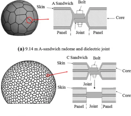
Composite material sandwich radomes (Fig.1) generally include low-density core materials (e.g. resin) and higher-density skin materials (e.g. fiber), and they are widely used in antenna-radome systems due to the high strength-to-weight ratio and good dielectric properties [1]. From the viewpoint of structure, sandwich radomes are composed of sandwich panels and fiber skin joints (Fig.1(a)). The joints are connected to each other by metal bolts and form the frame that is solid enough to undertake the load of exotic environment [2]. To get enough stiffness and strength, the joints should be much thicker than skins. Meanwhile the sandwich panels should be light in weight and low in transmission loss of electromagnetic wave propagation in order to achieve excellent radiation performance.
Radomes not only protect enclosed antennas against wind, rain, ice, snow and solar radiation, but also reduce the manufacturing cost and extend the service time of enclosed antennas [1,2]. However, from the viewpoint of electromagnetics, the radomes also lead to the degradation of radiation characteristics of the enclosed antennas, such as gain loss, boresight error and the rise in side-lobe level [3, 4], which can be represented by the distortion of Supported by National Natural Science Foundation of China (Grant
Nos. 51475348, 51305322 and 51490660), Open Foundation of State Key Laboratory of Mechanical Transmissions (SKLMT-KFKT-201409), and Fundamental Research Funds for the Central Universities of China.
& Na LI
1 Key Laboratory of Electronic Equipment Structure Design of
Ministry of Education, Xidian University, Xi’an 710071, China
2 State Key Laboratory of Mechanical Transmissions,
radiation pattern. Therefore, minimizing the degradation of radiation characteristics and maximizing structural stiff-ness are the prior purposes in the design of modern high-performance antenna-radome systems [5,6].
One of the main reasons of radiation pattern distortion is the change of phase difference caused by radome. In order to mitigate the phase difference, some novel approaches and materials have been proposed. Virone et al. installed a special metal periodic structure in the joints to reduce the phase difference between the joints and planes [7, 8]. A good agreement between the experimental and simulated results is reported [9], and the results indicate that their compensation strategy is valid and effective for mitigating the degradation caused by radomes. The absorbing mate-rials is used to reduce the effect of scattered field caused by induced current of the metal frame by enwrapping the metal bars [10].
A shaped reflector antenna is designed to change the original antenna phase distribution and compensate the phase distortion caused by dielectric radomes [11]. A shaped radome (nonuniform thickness) can also get a minimal phase difference and reduce the pattern distortion [12]. The degradation caused by glass fiber material error can be compensated [13] by grinding the geometrical thickness based on phase equivalent [14].
The metamaterial is applied to design a radome. By optimizing the structure parameters of the radome [15], the transmission coefficient of the plane radome is close to 1, and the degradation is almost invisible. Another metama-terial radome which has a planar centrosymmetric honey-comb-shaped structure can obtain a higher gain about 2.5 dB before the use of this metamaterial radome [16].
However, all these methods above are not easy to apply in practice. The methods in [7–14] need large modifications of the radomes or antennas and lead to high cost. The metamaterials radome is not suitable for large rotat-able antenna-radome system.
Phase compensation is a common method and could be applied to many electronic devices to improve their elec-tromagnetic performance, such as microstrip crossover structure [17], microwave patch antenna [18], large reflector antenna [11], and radome [12].
In order to mitigate the distortion of radiation pattern caused by composite materials radome, a novel compen-sation strategy based on phase compencompen-sation is proposed. Some simulation examples are presented to exhibit the validity of the novel strategy for multi-band system, mul-tipartite dielectric sandwich radomes.
2 Analysis Methods of Dielectric Sandwich
Radomes
The radome transmission coefficientTis used to expressed the transmission characteristics [1]
T ¼ TH2cos4bþTV2sin4bþ2THTVcos2bsin2bcosd
1=2
expjðugHÞ: ð1Þ
Whered =gH-gV,
u¼arctan TVsin 2bsind
THcos2bþTVsin2 bcosd;
THorTVis the amplitude of transmission coefficient of the wave,gis the inserted phase delay (IPD) according to the incident angles of different points, the subscripts H and V indicate the horizontal and vertical polarizations of the wave respectively, andbis the polarization angle.
Transmission coefficient and IPD are the functions of relative permittivity, loss tangent, thickness of radome materialsd and wavelengthk[1].
The IPD is expressed by
g¼x2p
k dcosc; ð2Þ
wherexis the initial phase andcis the angle of incidence. High frequency strategy such as physical optics (PO) [19] and geometric optics (GO) [20] are usually used in electromagnetic analysis of large radomes. In order to get a balance between the efficiency and accuracy of numerical analysis, the ray tracing-aperture integration method is adopted in this study [21,22], which means the assumption is infinitesimal wavelength. The electromagnetic field values of the antenna with a radome in the far field is given by [23,24]
Eðh;/Þ ¼
ZZ
S
Tðq;/Þfðq;/Þ exp ju q;ð /Þqdqd/; ð3Þ
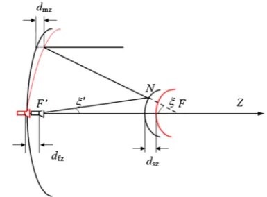
where (h,/) is the spherical coordinates of points in space, (q,/) is the polar coordinates of points in the reflector mapping to the aperture, E is the electric field value in pointRof the far field,fanduare the amplitude and phase distributing functions in the antenna’s original aperture respectively, T is the transmission coefficient of the radome, S is the original aperture and S0is the transmission aperture. Figure2 shows the schematic diagram of the variables in aperture and radome.
3 Compensation Strategy
To reduce the degradation of radiation characteristics, both transmission coefficient of dielectrics and inducted current of metal should be cut down. In this study, we mainly paid attention to the effects of transmission coefficient, and tried to reduce the phase difference in transmission aperture.
The phase of transmission coefficientTis the key factor that causes the distortion of radiation pattern. In the orig-inal aperture, the phase of the wave is a constant, namely the phase difference is 0, and the radiation pattern has no distortion without the radome. In contrast, with the radome, the phase ofTin the transmission aperture is not a constant, but varies with the incidence anglec. A differentcleads to a different IPD, thus induces a phase difference ofTin the transmission aperture, and finally causes the distortion of radiation pattern.
In antenna-radome systems, radome is an indispensible part and we cannot remove it, but we could change the phase distribution in the original aperture. If phase differ-ence in the original aperture has an inverse trend to that in the transmission aperture. The wave propagates through the
radome. Thus, the phase change will turn out to be a constant in the transmission aperture. Finally, an ideal radiation pattern can be obtained.
The reflector antenna is usually composed of a main reflector, a sub-reflector, and a feed. There are three ways to change the original aperture: shaping the main reflector, moving the sub-reflector and moving the feed, as shown in Fig.3.
3.1 Shaping the Main Reflector
A small displacement of one point in the main reflector along the axial directiondmzleads to the change of wave transmission distance from the sub-reflector to the original aperture. Figure3shows (the red line indicates the shaped reflector, moved feed or sub-reflector). The phase shift at the corresponding point in the original aperture is obtained as follows by the geometric relations [25]
gm¼ 2p
k dmzð1þcosnÞ; ð4Þ
wherenis the flare angle from the sub-reflector to the main reflector.
However, it is not practical to shape the main reflector for an installed reflector antenna.
3.2 Moving the Feed
Moving the feed along the axial directiondfz(offset focus) leads to the change of transmission distance from the feed to the sub-reflector as shown in Fig.3. The phase shift in the original aperture is calculated by [25]
gf ¼ 2p
k dfzcosn
0; ð5Þ
wheren0is the flare angle from the feed to the sub-reflector. In the center of the reflector, the flare anglen0minimizes to 0 and the phase shift is -2pdfz/k. In the edge of the reflector, the flare anglen0maximizes ton0maxand the phase
Fig. 2 Schematic diagram of the variables of aperture and radome schematic diagram
shift isgf ¼ 2pdfzcosn0max=k. Thus, the phase difference in the original aperture is
Dgf ¼
2p
k dfz 1cosn 0 max
: ð6Þ
3.3 Moving the Sub-Reflector
Similarly, the change of the wave transmission distance by moving the sub-reflector along the axial direction dsz includes two parts: one is from the feed to the sub-reflector and the other is from the sub-reflector to the main reflector. Therefore, the phase shift in the aperture is also compen-sated by two parts,
gs¼ 2p
k dsz cosnþcosn 0
ð Þ: ð7Þ
In the center of the reflector, both flare anglesn0andn minimize to 0 and the phase shift is 4pdsz/k. In the edge of the reflector, flare angles n0 and n maximize to n0max and nmax respectively, and the phase shift is gs¼2pdsz cosnmaxþcosn0max
=k. Thus, the phase dif-ference in the original aperture is
Dgs¼
2p
k dsz 2cosnmaxcosn 0 max
: ð8Þ
At the same point of the sub-reflector,n0maxis less thann, and their relationship is M¼tanðnmax=2Þ=tan n0max=2
, whereMis the amplification factor of the double reflector antenna, tan (n/2)=D/4f, D is the diameter of the main reflector, andfis the focal length.
In the aperture S, from the center to the edge, the two flare angles increase from 0 to n0max and nmax. If dfz is negative, namely the feed moves to the-Z direction, the distribution of phase difference in the original aperture is bigger in the center and smaller at the edge. Ifdsz is pos-itive, namely the sub-reflector moves to the?Zdirection, the distribution of the phase difference is similar to that with a negativedfz.
For a hemisphere radome in common use, the maximum cmaxlocates at the edge of the aperture, and the minimum cmin is 0 in the center of the aperture. Thus, the phase difference in the transmission aperture is
DgT¼gmaxgmin¼
2p
k dð1coscmaxÞ: ð9Þ
The distribution of DgT is smaller in the center and bigger at the edge, which is just inverse to the distribution of phase difference caused by negativedfzor positivedsz. Hence, the two-phase difference can offset each other and realize the compensation of the distortion of radiation pattern. This meansDgT ¼Dgf orDgT¼Dgs.
Then, the value of the offset focus of the feed is
dfz¼ Dgsk 2p 1cosn0max
: ð10Þ
The value of the offset focus of the sub-reflector is
dsz¼ DgTk
2p 2cosnmaxcosn0max
: ð11Þ
From the above analysis, it is known that the offset focus or Tleads to a phase difference in the transmission aperture and result in the distortion of radiation pattern as well as the degradation of radiation characteristics. However, if they work together, the degradation will be mitigated significantly. Flare anglen0is less thannat the same point in the sub-reflector. To compensate the sameDgT, the value ofdfzis larger than that ofdsz. Thus, the compensation by moving the sub-reflector is more appropriate than by moving the feed in practice. For most reflector antenna in engineering, both the sub-reflector and feed are fixed by bolts, if we adjust the bolts, the position of the sub-reflector or feed could be changed in a small range.
Oncedszis determined, the phase shiftgaof each point in the aperture can be obtained by Eq. (9). Then, substitute ga into Eq. (3), and the far field of an antenna with a radome can be expressed by
Eðh;/Þ ¼
ZZ
S
Tðq;/Þfðq;/Þ expjðu q;ð /Þ þgaÞqdqd/:
ð12Þ
By numerical integration, the calculation of Eq. (12) is implemented [22].
4 Simulation Examples
Two antenna-radome systems are used for simulation: (1) a 5.2 m reflector antenna with a 9.14 m one-piece dielectric sandwich radome (Fig.1(a)); (2) a 26 m antenna with a 40 m multipartite dielectric sandwich radome (Fig.1(b)). Two examples are used here for different purposes. The first purpose is to verify the effectiveness of the compen-sation strategy and its feasibility for the multi-band antenna-radome system. The second is to test the validity of the strategy for multipartite sandwich radomes.
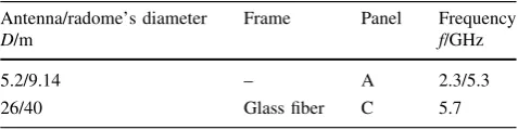
Table 1 Information of simulation examples
Antenna/radome’s diameter D/m
Frame Panel Frequency f/GHz
5.2/9.14 – A 2.3/5.3
Table1 gives some information of the examples. The parameters of the materials are listed in Table2. A-Sand-wich (Fig.1(a)) has two layers of skin (glass fiber) and one layer of core (foam). C-Sandwich (Fig.1(b)) has four layers of skin and two layers of core. For all examples, the original aperture follows an equal distribution of amplitude and phase, and the enclosed antenna points to the sky.
4.1 5.2 m reflector antenna with a 9.14 m one-piece radome
The one-piece radome means that there is no connected joint (ignored) between two panels. Hence, the jointed panels is considered to be a smooth hemisphere. The enclosed antenna is a Cassegrain antenna, and the focus diameter ratio is 0.4, withn0max =31°andnmax=80°.
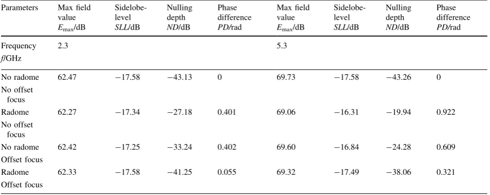
Four situations are considered in this example, including antenna without offset focus, antenna with offset focus, antenna under radome without offset focus and antenna under radome with offset focus. Some parameters of radiation characteristics are listed in Table3. As can be seen, the power loss (the change ofEmax) is about 0.2 dB at 2.3 GHz, the sidelobe-level (SLL) degradation is about 0.24 dB, the nulling depth (ND) degradation is about 16 dB, and the phase dif-ference (PD) in the transmission aperture is 0.4. The value of dszis 0.066k by Eq. (11), and the value of dfzis 0.44k by Eq. (10). The latter is much larger than the former, which indicates that moving sub reflector is more appropriate.
After compensation, the power loss is only 0.14 dB, which is less than the uncompensated value. The sidelobe-level (SLL) is improved greatly and approaches to the value of no radome. The nulling depth (ND) increases about 14 dB from -27.18 dB to -41.25 dB. The phase differ-ence (PD) in aperture is only 0.055, which is much less than the uncompensated value 0.4.
At 5.3 GHz, the results are similar to those at 2.3 GHz, but the degradation is relatively obvious. Before compen-sation, the power loss is 0.67 dB, the sidelobe-level degra-dation is 1.26 dB, the nulling depth degradegra-dation is 23 dB, and the phase difference of aperture is 0.92. Hence, thedsz will be more than 0.1k, which leads to the degradation of the enclosed reflector antenna. Previous studies show that if the value of the offset focus is less than 0.1k, the degradation is so tiny that can be ignored. In this viewpoint, there is a limitation for the compensation strategy, that is, the maxi-mum value of moving the sub-reflector is 0.1k. This means that if the phase difference of Tis too large, it cannot be compensated completely. In spite of this, a partial compen-sation of 0.1kis still available.
Here, after partial compensation, the sidelobe-level degradation reduces from 1.26 dB to 0.1 dB, the nulling depth degradation reduces from 23 dB to 5.2 dB, the power loss reduces from 0.67 dB to 0.4 dB, the phase difference reduces from 0.92 to 0.32.
For comparison, the results from antenna with offset focus are also involved in Table3. They are worse than the results from antenna without offset focus and those from antenna under radome with offset focus.
The above simulation results illuminate that, the radome leads to the degradations of radiation characteristics, and so does the offset focus. However, if the radome and the offset focus exist at the same time with appropriate values, the respective degradation of radome or offset focus can be
Table 2 Material parameters of the radome
Component Material Thickness d/mm
Permittivity
e/(Fm-1)
Loss tangent tand/(Wm-3)
Core Foam 50 1.15 0.009 8
Skin Glass fiber 0.5 4.20 0.026
Table 3 Main parameters of 9.14 m radome under 4 situations
Parameters Max field value Emax/dB
Sidelobe-level SLL/dB
Nulling depth ND/dB
Phase difference PD/rad
Max field value Emax/dB
Sidelobe-level SLL/dB
Nulling depth ND/dB
Phase difference PD/rad
Frequency f/GHz
2.3 5.3
No radome No offset
focus
62.47 -17.58 -43.13 0 69.73 -17.58 -43.26 0
Radome No offset
focus
62.27 -17.34 -27.18 0.401 69.06 -16.31 -19.94 0.922
No radome Offset focus
62.42 -17.25 -33.24 0.402 69.60 -16.84 -24.28 0.609
Radome Offset focus
significantly reduced. That means that the offset focus can compensate the degradation caused by radome, especially for sidelobe-level and nulling depth.
The distribution of phase difference of T is small in center and large at edge, while that of offset focus is large in center and small at edge. This result is just consistent with previous expositions. After compensation, the maxi-mum phase difference appears in the center and at the edge, and the minimum is a ring in the aperture. Overall, the whole phase difference is decreased greatly.
Notably, it is impossible to reduce the phase difference to zero by the compensation of offset focus, since the curvatures of the radome and the reflector are generally different.
4.2 26 m antenna with a 40 m multipartite dielectric radome
In practice, one-piece radomes are extremely rare, and most radomes are multipartite dielectric ones, especially for large radomes. In this simulation, both the panels and joints (composed of glass fiber) are included. The metal bolts are ignored. The effect of metal bolts is extremely small, since the area blocked by the bolts is so small as a literature indicated [26]. The thickness of joints is 30 mm. The joints are considered as thick dielectrics with an analysis strategy of ray tracing. The diameter of the enclosed antenna is 26 m, Mis 3, and focus diameter ratio is 0.3.
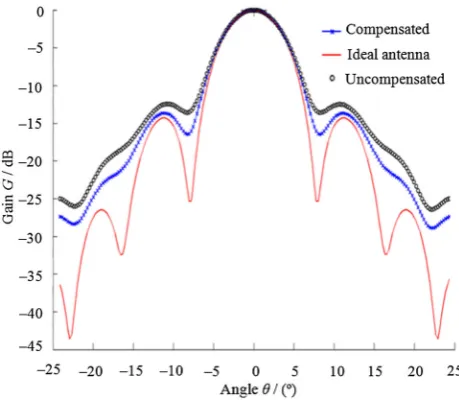
Three situations are considered in this example: ideal antenna without offset focus and radome, antenna under radome without offset focus, and antenna under radome with offset focus. Some parameters of the 40 m radome before and after compensation are listed in Table4. The degradation of radiation characteristics is serious owing to the radome thickness and the high frequency. The side-lobe level degradation is more than 2 dB which can not satisfy the design requirements. Since the phase differences of the radome exceeds the limitation, the value of the offset focus is set as 0.1k. The results are listed in Table4.
After compensation, the phase difference in the trans-mission aperture reduces from 2.65 to 2.26, the side-lobe level varies reduces from-12.45 dB to-13.65 dB and the degradation reduces from 2.1 dB to 0.9 dB. TheSLL can satisfy the design requirements. Meanwhile, the nulling
depth is improved by about 3 dB from -13.51 dB to
-16.47 dB. Owing to the asymmetry of radome joints, the right and leftSLLs are different.
The radiation patterns under three situations are shown in Fig.4. As can be seen, the improvements of the side-lobe level and the nulling depth are very illustrious. By careful observation, the improvement in beam width can also be detected. Related data are given in Table4.
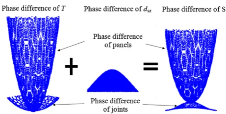
The distribution of phase differences of T, offset focus dsz, and compensated transmission aperture S’ are shown in Fig.5. The horizontal axis is the diameter of the aperture, and the vertical axis is the phase difference. The difference in phase difference of panels and joints is illustrated in the first picture. Because the thickness of joints is much less than that of panels, the phase difference of joints looks like a mesh in the bottom of the picture. After compensation, the reduction of phase difference is not obvious because of the 0.1klimitation, but this does not overthrow the effec-tiveness of the compensation.
The simulation results indicate that the offset focus can compensate the degradation of dielectric sandwich radomes and have a good potential application for metal-space frame radomes, especially the distortion of radiation patterns.
Table 4 Main parameters of the 40 m radome before and after compensation (5.7 GHz)
Parameters Max field value Emax/dB
Left sidelobe-level L-SLL/dB
Right sidelobe-level L-SLL/dB
Nulling depth ND/dB
Beam width BW/(°)
Phase difference PD/rad
Ideal antenna 107.22 -14.53 -14.53 -25.36 0.204 0
Before compensation 103.85 -12.45 -12.48 -13.51 0.221 2.65 After compensation 104.56 -13.65 -13.68 -16.47 0.212 2.26
5 Conclusions
(1) For the one-piece dielectric radome (9.14 m radome), more than 60% phase difference caused by radome is reduced, and more than 80% of the radiation char-acteristics degradation is compensated by the pro-posed compensation method, since the main reason of the degradation is the phase difference of the radome. (2) For the multipartite radome (40 m radome), although there are more reasons lead to the degradation (such as joints, frame and large phase difference of a practical radome), a satisfied results can still be achieved by the compensation strategy, about 50% of the degradation is reduced, especially for the sidelobe level and nulling depth.
(3) For the case of the large phase difference, the degradation is reduced partly by the proposed method. Because there is a limitation of the adjustable range of the sub-reflector or feed. (4) The method is only useful for a reflector antenna
with a standard parabolic dish. For a modified parabolic reflector antenna, reflector shaping is a appropriate method.
Open Access This article is distributed under the terms of the Creative Commons Attribution 4.0 International License (http://crea tivecommons.org/licenses/by/4.0/), which permits unrestricted use, distribution, and reproduction in any medium, provided you give appropriate credit to the original author(s) and the source, provide a link to the Creative Commons license, and indicate if changes were made.
References
1. KOZAKOFF D J. Analysis of radome-enclosed antennas[M]. Boston: Artech House, 2010.
2. GU¨ CU¨YEN E. Numerical Analysis of deteriorated sub-sea pipelines under environmental loads[J]. Chinese Journal of Mechanical Engineering, 2015, 28(6):1163–1170.
3. KIM D, YOU C S, HWANG W B. Effect of adhesive bonds on electrical performance in multi-layer composite antenna[J]. Composite Structures, 2009, 90: 413–417.
4. DALIRI A, WANG C H, GALEHDAR A, et al. A slot spiral in carbon-fibre composite laminate as a conformal load-bearing antenna[J]. Journal of Intelligent Material Systems and Struc-tures, 2013, 25(11): 1295–1305.
5. DAI F H, DU S Y. Analysis of the mechanical and electrical performance of conformal load-bearing antenna structure[C]//3rd Annual Meeting of the ASME/AIAA Smart Materials, Adaptive Structures, and Intelligent Systems Conference, Philadelphia, USA, Sep. 28–Oct. 1, 2010:17–20.
6. YOU C S, HWANG W B. Design of load-bearing antenna structures by embedding technology of microstrip antenna in composite sandwich structure[J].Composite Structures, 2005, 71: 378–382.
7. VIRONE G, TASCONE R, ADDAMO G, et al. Design strategy for large dielectric radome compensated joints[J].IEEE Antennas and Wireless Propagation Letters, 2009, 8: 546–549.
8. VIRONE G, TASCONE R, OLIVIERI A, et al. A waveguide/ free-space measurement setup for panels and joints of large dielectric radomes[C]//Proc. Int. Conf. Electromagn. Adv. Appl., Turin, Italy, Sep. 17–21, 2007: 792–794.
9. ADDAMO G, VIRONE G, PEVERINI O A, et al. Experimental results on compensated joints for large dielectric radomes[C]// Electromagnetic in Advanced Applications (ICEAA) 2011 Inter-national Conference, Torino, France, Sep. 12–16, 2011: 1275–1276.
10. ZHANG C F, MI X L, TANG W, et al. Application of radar absorbing material in design of metal space frame radom[C]// Cross Strait Quad-Regional Radio Science and Wireless Tech-nology Conference, Harbin, China, July 26–30, 2011: 222–225. 11. XU W Y, DUAN B Y, LI P, et al. Novel compensation method
for EM performance of dielectric radome based on reflector shaping[J]. IET Microwaves Antennas and Propagation, 2015, 9(2): 125–132.
12. XU W Y, DUAN B Y, LI P, et al. Multiobjective particle swarm optimization of boresight error and transmission loss for airborne radomes[J]. IEEE Transactions on Antennas and Propagation, 2014, 62(11): 5880–5885.
13. YI W, JIANG Z L, SHAO W X, et al. Error compensation of thin plate-shape part with prebending method in face milling[J]. Chinese Journal of Mechanical Engineering, 2015, 28(1): 88–95. 14. GUO D M, ZHANG C B, KANG R K, et al. Inverse method for determining grinding area and material removal amount in grinding radome[J].Key Eng. Mater., 2007, 329: 81–86. 15. BASIRY R, ABIRI H, YAHAGHI A. Electromagnetic
perfor-mance analysis of omega-type metamaterial radomes[J]. Inter-national Journal of RF and Microwave Computer-Aided Engineering, 2011, 21(6): 665–673.
16. ZHENG K S, LI N J, REN A K, et al. Designing and measure-ment of a single layered planar gain-enhanced antenna radome with metamaterials[J]. Journal of Electromagnetic Waves and Applications, 2012, 26(4): 436–445.
17. EOM S Y, BATGEREL A, MINZ L. Compact broadband microstrip crossover with isolation improvement and phase compensation[J]. IEEE Microwave and Wireless Components Letters, 2014, 24(7): 481–483.
18. CHEN K, YANG Z J, FENG Y J, et al. Improving microwave antenna gain and bandwidth with phase compensation metasur-face[J].AIP Advances, 2015, 5, 067152: 1–8.
19. MONEUM M A A, SHEN Z, VOLAKIS J L, et al. Hybrid PO-MOM analysis of large axi-symmetric radomes[J].IEEE Trans-actions on Antennas and Propagation, 2001, 49(12): 1657–1660. 20. EINZIGER P D, FELSON L B. Ray analysis of two-dimensional radomes[J]. IEEE Transactions on Antennas and Propagation, 1983, 31(6): 870–884.
21. DUAN B Y, WANG C S. Reflector antenna sdistortion using MEFCM[J].IEEE Transactions on Antennas Propagation, 2009, 57(10): 3409–3413.
22. LI P, DUAN B Y, WANG W, et al. Electromechanical coupling analysis of ground reflector antennas under solar radiation[J]. IEEE Antennas and Propagation Magazine, 2012, 54(5): 40–57. 23. XU W Y, DUAN B Y, LI P, et al. EM performance analysis of radomes with material properties errors[J].IEEE Antennas and Wireless Propagation Letters, 2014, 13: 848–851.
24. XU W Y, DUAN B Y, LI P, et al. EM analysis of deformed metal space frame radome[J]. IEEE Antennas and Wireless Propaga-tion Letters.2014, 13: 130–133.
25. YE S H, LI Z G.design of antenna structure[M]. Xian: Xidian University Press, 1986.(Chinese)
26. LAVRENCH W. Electrical performance of rigid ground rado-mes[J]. IRE Transactions on Antennas and Propagation, 1960, 8(11): 548–558.
Peng LI,born in 1981, is currently an associate professor at Key Laboratory of Electronic Equipment Structure Design of Ministry of
Education, Xidian University, China. He received his PhD degree fromXidian University, China, in 2011. His research interests include numerical computation of mult-field-coupled problem of electronic devices. Tel:?86-29-88203040; E-mail: [email protected]
Na LI, born in 1982, is currently an associate professor at Key Laboratory of Electronic Equipment Structure Design of Ministry of Education, Xidian University, China. E-mail: [email protected]
Wanyen XU, born in 1989, is currently an lecturer at Xidian University, China. He received his PhD degree on mechanical engineering atXidian University, China, in 2015.