Islanding Detection of Synchronous Machine-Based DGs using
Average Frequency Based Index
M. Bakhshi*, R. Noroozian* and G. B. Gharehpetian**
Abstract: Identification of intentional and unintentional islanding situations of Dispersed
Generators (DGs) is one of the most important protection concerns in power systems. Considering safety and reliability problems of distribution networks, an exact diagnosis index is required to discriminate the loss of the main network from the existing parallel operation. Hence, this paper introduces a new islanding detection method for synchronous machine–based DGs. This method uses the average value of the generator frequency to calculate a new detection index. The proposed method is an effective supplement of the Over/Under Frequency Protection (OFP/UFP) system. The analytical equations and simulation results are used to assess the performance of the proposed method under various scenarios such as different types of faults, load changes and capacitor bank switching. To show the effectiveness of the proposed method, it is compared with the performance of both ROCOF and ROCOFOP methods.
Keywords: Islanding detection, Non-detection zone, Passive methods, Synchronous
machine-based Distributed Generation (DG).
1 Introduction1
Nowadays, DG has been broadly used in distribution power systems. It can supply electricity secure to customers, be active in a deregulation of the electricity market, increase the reliability and decrease environmental concerns [1, 2]. The islanding identification for the connection of distributed generators to distribution networks is an important issue. According to IEEE standard 1547-2003, the islanding condition is defined as a situation in which a part of an electric power system is solely energized and separated from the rest of the system [3]. Failure to islanding detection can lead to several negative impacts to the generators and connected loads, as follows [4, 5]:
1. The islanded grid cannot control its frequency and voltage. This earns result in equipment damages.
2. This condition may cause safety hazards to utility workers and customers.
Therefore, the islanding situation must be detected as soon as possible. Many islanding detection methods
Iranian Journal of Electrical & Electronic Engineering, 2013. Paper first received 24 Jan. 2013 and in revised form 10 Mar. 2013. * The Authors are with the Department of Electrical Engineering, University of Zanjan, Zanjan.
** The Author is with the Electrical Engineering Department, Amirkabir University of Technology, Tehran, Iran.
E-maisl: [email protected], [email protected] and [email protected].
have been proposed, which can be classified into two main categories. Remote methods, such as power line communication [6] and supervisory control and data acquisition [7] methods. They do not have Non-Detection Zone (NDZ) and are more reliable than the local methods but more expensive. NDZs are defined as a loading condition for which an islanding detection method would fail to operate in a timely manner [8].
The local methods can be classified into two major groups: active and passive methods. According to the active methods, islanding is detected based on adding a perturbation signal into the system. The perturbation signals in parallel operation have no significant effect; but in the case of the loss of main grid, these signals are detected. Some of active methods, which have been recently introduced, include positive feedback for active and reactive power loops in governor and excitation system of synchronous DGs [9], injection a negative sequence of current through the interface Voltage-Sourced Converter (VSC) [10], Sandia frequency and voltage shift methods [11] and harmonic amplification factor, which is based on the voltage change at the Point of Common Coupling (PCC) [4].
Passive methods are based on measuring local parameters of DG and comparing it with preset value. Passive methods, which have been proposed, include Over/Under Frequency/Voltage Protections (OFP/UFP and OVP/UVP) and rate of change of frequency over the time [12-14]. Vector surge relay is the other
Bakhshi et al solution, wh passive meth e.g., rate of [16] and rate For inverter-methods bas power of the respectively. Filtering (KF adaptive fuz major metho islanding sit based and sy investigated very effectiv Classification have been r reviewed in [ of islanding hybrid metho [5, 27], the methods hav the combina methods. Al NDZ than th quality of the Most of parameter, h monitoring NDZ of pas 17]. In this p used to reduc uses only one from the vie same perfor monitoring m
The pape method is de results of si comparison methods is c the conclusio 2 Proposed 2.1 Frequ
For a Sy which is op network and equation is d
ω ω dt P
d H m b = 2
where, H constan coefficient, m
l: Islanding D hich has been hods use two change of fre e of change o -based DGs, sed on using e DG has bee Artificial Ne F), estimation zzy and duff ods, which ar tuation. These ynchronous–m in [19-24]. ve but also n-based island recently deve [25, 26]. The
detection tec ods have been combination ve been invest ation of both
lthough the a he passive me e system [18].
the passive m have a large of two param sive methods paper, the ave ce NDZ of OF e parameter to ewpoint of re rmance and c methods.
er is organiz escribed in se imulations an of proposed carried out an ons.
d Method uency Deviati
Island ynchronous D perating in p d feeds the lo defined [30, 31
ω D P
Pm − e −
, ωb, D, Pm nt, synchronou
mechanical an
Detection of Sy n explained in
o parameters equency over of phase angle
two new isla g DC voltag en considered eural Network based method fing oscillator re very efficie e methods, i machine based Although the have a lot ding detection eloped, are p
combination o chniques whic n introduced i n of both act tigated wherea
communicat active metho ethods but de .
methods, mon e NDZ, whi meters furthe s and have a erage value of FP/UFP. The p o detect island educing the N capability as zed as follow
ection 2. Sect nd discussion d method wi nd finally sect
on for Grid-C ded Modes Distributed G
parallel with cal load, the 1]:
and Pe are ge us speed of DG nd electrical p
ynchronous M n [15]. Some simultaneou the active pow e difference [
anding detect e and refere d in [8] and [ k (ANN), Kalm
ds, application rs are the ot ent to detect in both inver d DGs, have b ese methods of complex n schemes, wh passive meth of different ty ch are known in [5, 27, 28] tive and pass as [28] expres tion and pass ds have sma egrade the pow nitoring only
ile simultane er decreases
small NDZ [ f the frequency
proposed meth ding situation
NDZ, it has two parame ws: the propo
tion 3 shows ns. In section ith two pass tion 5 represe
Connected an
Generator (SD a utility m following sw
enerator inerti G, damping power of the D
Machine-Based e of usly, wer 17]. tion ence 18], man n of ther the rter-been are xity. hich hods ypes n as . In sive sses sive aller wer one eous the [16, y is hod and the ters osed the n 4 sive ents nd DG), main wing (1) ia DG, Fig res dif and 1) pre wr 2 ω H wh coe the 1, dif (2) init rot
δ
Δ f Δ wh n ω ς =ω
d θ= the sin thed DGs using …
g. 1 Synchroniz
spectively. Th fferent modes d loss of main
Grid-Conne In this mode esented in ap
itten: 2 2 δ ω + Δ d D dt d H b
here, the term efficient. This e dynamic beh shows the va fferent conditi ) and conside
tial conditions tor angle devia
1 ) ( 0
ς
δ
δ
− Δ = t 1 2 ) (t f nπ
ω
Δ − =here, we have:
H P n 2 cos max = . 2 2 H Pm
D = 1
ς
ω
− = n d ) ( cos−1ς=
Considering e frequency an nusoidal wave ese signals wil
… zing coefficient
e swing equat ; parallel ope n network. ected Mode of e, based on th ppendix, the f
c
max
δ =−
Δ P dt d ) cos(
max Δδ
P
s parameter ha havior of the s alues of the sy ons of the pow ering Δδ(0)= s, following re ations can be
sin(
2
ω
ς
ςω −
e nt
sin
2
0 e nt
ς
δ
−ςω − ΔH b ). (δ0 ω
) cos( 0 ax δ ωb 2
ς
Eq. (3) and E nd rotor angle eform and afte ll be equal to tin different con
tion must be s eration with m f SDG
he manipulatio following equ
) cos(Δδ
is known as s as a very imp synchronous g ynchronizing wer system. B
0
δ
Δ
= and Δ esponses for f obtained:
)
θ
ω
dt+) n(
ω
dt
Eq. (4), it can e deviations ha er a while the
the zero.
95
nditions. solved for two main network on of Eq. (1), uation can be (2)
synchronizing portant role in generator. Fig. coefficient in By solving Eq. 0 ) 0 ( = Δω as frequency and (3) (4) (5) (6) (7) (8) n be said that ave a damped amplitude of o k , e g n . n . s d ) t d f
2) Loss of Main Grid:
In this mode, the response of the frequency to a loss of main grid is determined. In the islanding situation, the transmitted power between DG and main network reaches to zero (see Fig. 1). It means that the synchronizing coefficient Pmaxcos(Δδ) must be equal to zero. Therefore, in Eq. (2), we have:
0 2
2 2
= Δ + Δ
dt d D dt d H
b
δ δ
ω (9) By solving Eq. (9) with Δδ(0)=ΔPωb/2H and
D P/ 2 ) 0
( = Δ
Δω π as initial conditions, the following response for frequency deviations can be obtained:
(
e nt)
DP t
f()= Δ 1− −2ςω
Δ (10) Here, ΔP is the active power imbalance. By comparing Eq. (4) and Eq. (10), it can be seen that frequency deviations in grid-connected and islanded modes are different. When the real power mismatches (ΔP) causes transients in the islanded portion, the frequency of DG increases or decreases. Therefore, the aforementioned frequency deviations can be used to detect the islanding condition.
2.2 Fundamentals of Proposed Method In this section, the average value of the frequency (i.e., Δfmean) is determined and a new detection index is introduced. The average value of the frequency deviation is written, as follows:
∫
Δ =Δ Td
d
mean f t dt T
f 1 0 ( ). (11) where, Td is the fundamental period of the frequency deviation determined by Eq. (7), as follows:
2
1 2 2
2
ς ω
π π
π ω
− =
⇒ = =
n d d d
d f T T (12) Now, Eq. (11) should be calculated for both operation modes.
a) For grid-connected mode, by Eq. (4) and Eq. (11), the frequency deviation will be determined, as follows:
( )
t dte T
f Td n
d t n
d on
mean sin .
1 2 1
0 2
0
∫
−−
− Δ − =
Δ ω
ς π
δ
ω ςω
(
)
( )
⎥⎦ ⎤ ⎢⎣ ⎡
+ − −
Δ −
= 2 − 2
2
0 1
1 2 1
d n
T d
n d
d n
e
T ςω ω
ω ς π
δ
ω ςω
(13)
Using Eq. (7), the simpler form can be obtained, as follows:
[
nTd]
don
mean e
T
f ςω
π
δ −
− −
Δ − =
Δ 1
2
0 (14)
where, Δδ0 is the initial rotor angle deviation which can
be created in different disturbances of the power systems.
b) For islanding condition, by Eq. (10) and Eq. (11), the frequency deviation will be calculated, as follows:
(
e)
dtD P T
f Td nt
d off
mean 1 .
1
0
2
∫
−− −
Δ =
Δ ςω
⎥ ⎦ ⎤ ⎢
⎣ ⎡
− +
Δ
= −
n T
n d d
d n
e T
D T
P
ςω ςω
ςω
2 1 2
1 .
2
(15)
To analyze the performance of the proposed method and assessment of its Non–Detection Zone (NDZ), the critical power imbalance of the method must be calculated. The critical power imbalance is the minimum power deviation which one islanding detection method can discriminate between two operation modes using it. The mentioned power deviation is described as a difference between produced and absorbed electrical power by DGs and loads, respectively.
The critical power imbalance of the proposed method is determined by the following inequality:
1 > Δ
Δ
− −
on mean
off mean f f
(16) Eq. (16), can be rewritten, as follows:
[
1]
12
2 1 2
1 .
0 2
> −
Δ −
⎥ ⎦ ⎤ ⎢
⎣ ⎡
− +
Δ
− −
d n
d n
T d
n T n d d
e T
e T
D T
P
ςω ςω
π δ
ςω ςω
(17)
This inequality can be also written in the following form:
[
]
ψςω ςω
π δ
ςω ςω
= ⎥ ⎦ ⎤ ⎢
⎣ ⎡
− +
− Δ
> Δ
− −
n T
n d
T
d n
d n
e T
e D
P
2 1 2
1 1
2 2
0 (18)
Then, the non-detection zone of proposed method is introduced, as follows:
ψ ψ<Δ <
− PNDZ (19) To study the performance of the proposed method, the
critical power imbalance (i.e., ΔPcritical = ψ) and the coefficient k = ζωnTd should be considered. The time
Bakhshi et al
Fig. 2 Variatio
constant of th by τ = 1/ζωn settling time (i.e., tsettling = time of the times of the f
5 .
0 <ςωnTd < Using Eq. can be expre
0 f T D d π δ ψ = Δ
where, f(k) is
(
(
k k k f 2 1 ) ( − =Fig. 2, sh the maximum worst case is initial rotor a of a disturban in radian an Eq. (21) can
180 0 Δ = d T D δ ψ
In Eq. (2 has a vital ro Although, D/
the synchron values but its smaller than different typ
D/Td is bett
paragraphs, synchronous From Eq. (5) written:
l: Islanding D
on of f(k) versus
he frequency
nand for all d
e is about fou 4/ζωn) [32]. I
frequency dev fundamental p 5 . 0 2 < or
. (18), the cri ssed by the fo
) (k
f
s defined, as fo
)
)
k k e e 2 1 1 − − + − −hows f(k) vers m value of f(k
s f (2) = 0.572 angle deviatio nce in the pow nd it can be
be rewritten,
5729 . 0
×
23), D/Td is a
ole to reduce N
/Td is charact
nous distribute s range can be n 5 percent pes of synchr ter to be low
it will be s distributed g ) and Eq. (6) t
Detection of Sy
s k.
deviation sign damped sinuso ur times of th In the other w viation signal period. Theref
2 < <k itical active p ollowing equat
follows:
sus k. Accordi
k) is 0.5733 at 29 for ψ. In Eq on that occurs wer network. T
converted int as follows:
an important p NDZ of the p terized by all ed generator a e estimated. T
in the propo ronous distrib wer than 1. I shown that D
generators is the following
ynchronous M
nal is represen oidal signals, he time const words, the settl l is about 2 t fore, we have: (
power imbala tion:
(
(
ing to this figu t k = 2.2. So, q. (21), Δδ0 is
s in the prese This paramete to degree. Th
(
parameter wh proposed meth of parameters and has differ o achieve a N osed method buted generat
In the follow
D/Td in exist
smaller than equations can Machine-Based nted the tant ling to 8 : 20) ance (21) (22) ure, the the ence er is hen, 23) hich hod. s of rent NDZ for tors, wing ting n 1. n be ςω or or wh ine the fol d T D eva Th syn net fun cha stu 1.5 d T D sho tha osc dif syn for Fo Fig
d DGs using …
b n D H Dω ω 4 ⇒ = H D Td 4 , = ⎜⎜ ⎝ ⎛ = 4 , b d T k T D r ω
here, ωb and
ertia constant, e worst case llows:
⎜⎜ ⎝ ⎛ ≅0.0212
d T
H D
In this equa aluate the D/T
his constant de nchronous d tworks is low ndamental per anged from 0 udy, which wi 5s and Td = 0.3
0 0212 . 0 ⎜ ⎝ ⎛ ≅ d D
As it can be ould be noted at the high
cillations. In F fferent values nchronous DG r four cases ha
2 . 0 5 . 0 ⎩ ⎨ ⎧ = = d T H or
g. 3 Behavior of
… b n H D ω ςω . 4 = H T H b b n d ω ω
ςω ) 4
( = ⎟⎟ ⎠ ⎞ 2 d T H
H are synch respectively. for the bigg
⎟⎟ ⎠ ⎞ 2 d H
ation, H is a
Td. According
epends on the distributed ge wer than four
riod of the fre 0.15 to 1.5s. ill be presente 33s. Thus, we
292 . 0 33 . 5 . 1
2⎟≅
⎠ ⎞
e seen the res d that Td is pro
value of H
Fig. 3, the roto s of inertia G have been s
as been determ
2 . 0 2 5 ≅ ⇒ d T D
f rotor speed de
k H b hronous speed For k = 2 and gest value of
an important to [30, 31], 0 machine size enerators in
[9, 13, 25, 2 equency devia
For example ed in the next
have:
2 sult is smaller oportional to H
H needs mo
or speed varia constant of simulated and mined, as follo
190
eviation for diff
97
(24)
d of DG and d ωb = 2π.60,
f D/Td is, as
(25)
parameter to 0.5s≤H≤ 10s.
e. Hence, H of distribution 29]. Then, the ation or Td, is
e, in the case t section, H =
(26)
r than one. It
H. this means ore time for ations for four one typical d shown. D/Td
ows:
(27)
ferent H. d , s o . f n e s e = t s r r l d )
19875 . 0 4
. 0
5 . 1
≅ ⇒ ⎩
⎨ ⎧
= =
d
d T
D T
H
For (28)
6 17 . 0 6
. 0
0 . 3
≅ ⇒ ⎩
⎨ ⎧
= =
d
d T
D T
H
For (29)
17306 . 0 7
. 0
0 . 4
≅ ⇒ ⎩
⎨ ⎧
= =
d
d T
D T
H
For (30)
Considering the aforementioned results, it can be said that D/Td for the most of DGs is smaller than one and in the worst case, it is equal to 1. Consequently, D/Td = 1 can be substituted in Eq. (23), as follows:
180 5729 .
0 δ0
ψ = Δ (31) In this equation, Δδ0 has a vital role to determine the limits of islanding and non–islanding conditions. To illustrate the discrimination procedure of the proposed method, the following two criterions must be considered.
1. If Δδ0≤ 10°
For this condition, the frequency variations certainly are in acceptable range (i.e., 59.3Hz ≤ f ≤60.5Hz) [3].
Thus, over/under frequency protections will not operate. Consequently, NDZ could be written, as follows:
03182 . 0 180
10 5729 . 0 )
(pu ≤ ≅
ψ
% .182 3 ≤
ψ
(32) 2. If Δδ0≥ 10°For this situation, frequency probably exceeds its acceptable range and over/under frequency protections for more cases will operate. If frequency variations were
remained in acceptable range, NDZ of the method could be achieved, as follows:
03182 . 0 180
10 5729 . 0 )
(pu ≥ ≅
ψ
% .182 3 ≥
ψ
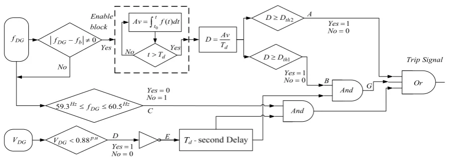
(33)2.3 Procedure of Proposed Method
In this subsection, the calculation procedure of fmean is described. To calculate the fmean, both procedures, i.e. the voltage zero crossing and the rotor speed have used. After the computation of fmean, the detection index is calculated, as follows:
off on mean g off
on k f
D / = . Δ − / (34)
where, Δfmean is (fb − fmean) and fb and D are the fundamental frequency and the detection index of the proposed method, respectively. The kg is a gain, adjusted to 100. The flowchart of the proposed method is shown in Fig. 4. In this figure, Dth1 is the first
threshold value of the detection index, which can be acquired from comparing islanding and non- islanding cases. Using Eqs. (14) and (15) for ΔP = 3% and Δδ0 =
10°, different detection parameters have been
represented in Table 1.
Table 1.Detection indices for both case study systems.
Don *
Doff Dth1 Dth2
First
system SDG 8.10 10.32 8 32
Second system
Gas
Turbine 9.62 12.86 9 36
Diesel
Generator 10.37 13.42 10 40
*The unit of D is Hertz.
∫
= tt f t dt Av
0 ()
d
T t>
0
≠ − b
DG f
f
d
T Av D=
1 th
D D≥
Hz DG
Hz f 60.5
3 .
59 ≤ ≤
u p DG
V <0.88 .
2 th
D D≥ block
Enable
No
0
= No
Yes
1
= Yes
And Or
DG
f
DG
V
Yes
No TripSignal
0
= No=1 Yes
0
= No=1 Yes
1
= No=0 Yes
A
B
C
D E
G
And
Fig. 4 Flowchart of proposed method.
Bakhshi et al: Islanding Detection of Synchronous Machine-Based DGs using … 99 3 Simulation Results and Discussion
To verify the effectiveness of the proposed method, various islanding and non-islanding occurrences have been applied on the case study systems as shown in Figs. 5 and 6. For both under study systems, sixth–order model of SDG for simulations is used. More information about first and second case study systems can be found in [12] and [29], respectively. It should be noted that all simulations have been carried out in Matlab/SimPowerSystem software environment. The most important disturbances which may result in wrong performance of islanding detection methods are short circuit faults, load variations and capacitor bank switching. In this paper, 55 different islanding and non– islanding cases have been studied by the proposed
Fig. 5 Single line diagram of first case study system.
Fig. 6 Single line diagram of second case study system.
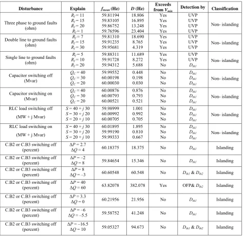
Table 2.Classification of different islanding and non-islanding conditions using proposed method on the first system.
Disturbance Explain fmean (Hz) D (Hz)
Exceeds from Vmin
Detection by Classification
Three phase to ground faults (ohm)
Rf = 11 Rf = 15 Rf = 20
Rf= 1
59.81194 59.83105 59.86752 59.76596
18.806 16.895 13.248 23.404
Yes Yes Yes Yes
UVP UVP UVP UVP
Non- islanding
Double line to ground faults (ohm)
Rf= 7 Rf = 15 Rf = 30
59.81310 59.91235 59.95681
18.690 8.765 4.319
Yes Yes Yes
UVP UVP
UVP Non- islanding
Single line to ground faults (ohm)
Rf = 5 Rf = 10 Rf = 20
59.88311 59.91728 59.94312
11.689 8.272 5.688
Yes Yes
No
UVP UVP Dth1
Non- islanding
Capacitor switching off (Mvar)
QC = 40 QC = 30 QC = 20
59.99552 60.00198 60.00030
0.448 0.198 0.030
No No No
Dth1 Dth1 Dth1
Non- islanding
Capacitor switching on (Mvar)
QC = 40 QC = 30 QC = 20
60.00876 60.00793 60.00521
0.876 0.793 0.521
No No No
Dth1 Dth1 Dth1
Non- islanding
RLC load switching off (MW + j Mvar)
S = 40 + j 30 S = 30 + j 20 S = 20 + j 10
59.98999 60.00992 60.00705
1.001 0.992 0.705
No No No
Dth1 Dth1 Dth1
Non- islanding
RLC load switching on
(MW + j Mvar)
S = 40 + j 30 S = 30 + j 20 S = 20 + j 10
60.01895 59.99190 59.99333
1.895 0.810 0.667
No No No
Dth1 Dth1 Dth1
Non- islanding
C.B2 or C.B3 switching off (percent)
ΔP = 2.7
ΔQ = 4 60.18375 18.375 No Dth1 Islanding C.B2 or C.B3 switching off
(percent) ΔΔPQ = –2 = 8 59.84654 15.346 No Dth1 Islanding C.B2 or C.B3 switching off
(percent)
ΔP = 8
ΔQ = –3 60.60548 60.548 No Dth1 & Dth2 Islanding C.B2 or C.B3 switching off
(percent)
ΔP = 40
ΔQ = 60 63.82078 382.078 Yes OFP& Dth2 Islanding
C.B2 or C.B3 switching off (percent)
ΔP = 3.3
ΔQ = 0 60.21956 21.956 No Dth1 Islanding
C.B2 or C.B3 switching off (percent)
ΔP = –6
ΔQ = –5.5 59.58752 41.248 No Dth1 Islanding
C.B2 or C.B3 switching off (percent)
ΔP = –16.5
ΔQ = 10 59.05327 94.673 No Dth1 & Dth2 Islanding
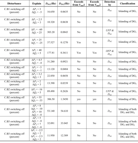
Table 3.Classification of different Islanding conditions using proposed method on the second system.
Disturbance Explain DDG1(Hz) DDG2(Hz)
Exceeds from Vmin1
Exceeds from Vmin2
Detection
by Classification
C.B1 switching off (percent)
ΔP1 = 3
ΔQ1 = –5 16.650 0.0635 No No
Dth1 Islanding of DG
1
C.B1 switching off (percent)
ΔP1 = 2.5
ΔQ1 = 3 10.320 0.0638 No No
Dth1 Islanding of DG
1
C.B1 switching off
(percent) ΔΔPQ1 = –60 1 = 25 303.20 0.0843 No No
UFP & Dth1
Islanding of DG1
C.B1 switching off
(percent) ΔΔQP11 = –25 = 25 37.527 0.1270 Yes Yes
Dth2 Islanding of DG
1
C.B1 switching off
(percent) ΔΔPQ11 = 40 = 5 177.81 0.3611 Yes Yes
OFP & Dth2
Islanding of DG1
C.B2 switching off
(percent) ΔΔPQ22 = 4.5 = –4 31.280 0.0921 No No Dth1 Islanding of DG2
C.B2 switching off (percent)
ΔP2 = –3
ΔQ2 = –1 13.120 0.0484 No No Dth1 Islanding of DG2
C.B2 switching off (percent)
ΔP2 = 3.2
ΔQ2 = 3 22.850 0.0658 No No Dth1 Islanding of DG2
C.B2 switching off (percent)
ΔP2 = 2
ΔQ2 = 3 13.390 0.0339 No No Dth1 Islanding of DG2
C.B2 switching off (percent)
ΔP2 = –16
ΔQ2 = 5 89.490 0.2626 No No UFP & D
th1
Islanding of DG2
C.B2 switching off (percent)
ΔP2 = 55
ΔQ2 = –33 306.50 1.5450 yes yes Dth2 Islanding of DG2
C.B3 switching off (percent)
ΔP1 = 8
ΔQ1 = –10
ΔP2 = 10
ΔQ2 = –8
53.140 54.610 No No Dth1 Islanding of both DG
1 and DG2
C.B3 switching off (percent)
ΔP1 = 5
ΔQ1 = –8
ΔP2 = 7
ΔQ2 = –6
32.091 33.045 No No Dth1 Islanding of both DG
1 and DG2
C.B3 switching off (percent)
ΔP1 = –2.5
ΔQ1 = 2
ΔP2 = –2.5
ΔQ2 = 2
11.950 12.389 No No Dth1 Islanding of both DG
1 and DG2
method. The phase–locked loop block with three phase voltage of DG is used to achieve the frequency waveform. From Fig. 4, the proposed method has been introduced as supplementary protection of Over/Under Frequency Protection (OFP/UFP). To prevent sending of any undesired trip signal for sever disturbances like three phases faults, Under Voltage Protection (UVP) has also been used. The acceptable range of voltage is 0.88 pu–1.1 pu [3]. In the case of frequency and regarding the IEEE standard–1547, variations should be in the range of 59.3-60.5 Hz [3]. The simulated short circuit faults are Single Line to Ground (SLG), Double Line to Ground (DLG) and three phases with different fault
resistances. It should be noted that the short circuit duration of all faults is 6 cycles and both islanding and non–islanding disturbances start at t = 2s.
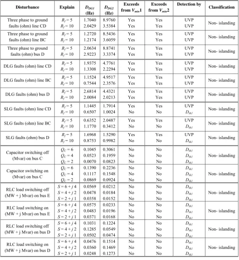
Eventually, Tables 2-4, present the detection index for all of the disturbances. Table 2, depicts the tested results of the proposed method on the first case study system and Tables 3, 4 are related to the second case study system.
In these tables, the subscript “1” and “2” indicates gas turbine and diesel generator on the second case study systems. From Table 2, although, it can be seen for more faults, the detection index exceeds from first threshold but UVP detects these disturbances as non-
Bakhshi et al: Islanding Detection of Synchronous Machine-Based DGs using … 101
Table 4.Classification of different Non–islanding conditions using proposed method on the second system.
Disturbance Explain DDG1
(Hz)
DDG2
(Hz)
Exceeds from Vmin1
Exceeds from Vmin2
Detection by
Classification
Three phase to ground faults (ohm) line CD
Rf = 5 Rf = 10
1.7040 2.0429
8.9760 3.5384
Yes Yes
Yes Yes
UVP
UVP Non- islanding Three phase to ground
faults (ohm) line BC
Rf = 5 Rf = 10
1.2720 1.2174
8.5436 3.6059
Yes Yes
Yes Yes
UVP
UVP Non- islanding
Three phase to ground faults (ohm) bus D
Rf = 5 Rf = 10
2.0634 2.9223
8.8741 3.3374
Yes Yes
Yes Yes
UVP
UVP Non- islanding
DLG faults (ohm) line CD Rf= 5 Rf = 10
1.9375 1.3308
4.7761 2.2294
Yes Yes
Yes Yes
UVP
UVP Non- islanding
DLG faults (ohm) line BC Rf= 5 Rf = 10
1.1524 0.7544
4.9517 2.3576
Yes Yes
Yes Yes
UVP
UVP Non- islanding
DLG faults (ohm) bus D Rf= 5 Rf = 10
2.6814 2.0084
4.4321 2.0213
Yes Yes
Yes Yes
UVP
UVP Non- islanding
SLG faults (ohm) line CD Rf= 5 Rf = 10
1.1445 0.6507
1.7914 1.0024
Yes No
Yes No
UVP Dth1
Non- islanding
SLG faults (ohm) line BC Rf= 5 Rf = 10
0.6352 1.1770
2.0487 0.3412
Yes No
Yes No
UVP Dth1
Non- islanding
SLG faults (ohm) bus D Rf= 5 Rf = 10
1.6968 0.8753
1.5290 0.9982
Yes No
Yes No
UVP Dth1
Non- islanding
Capacitor switching off (Mvar) on bus C
QC = 6 QC = 4 QC = 2
0.1045 0.0523 0.0070
0.3061 0.1959 0.0823
No No No
No No No
Dth1 Dth1 Dth1
Non- islanding
Capacitor switching on (Mvar) on bus C
QC = 6 QC = 4 QC = 2
0.1390 0.1117 0.0869
0.2236 0.1548 0.0924
No No No
No No No
Dth1 Dth1 Dth1
Non- islanding
RLC load switching off (MW + j Mvar) on bus E
S = 6 + j 4 S = 4 + j 2 S = 2 + j 1
0.0569 0.0478 0.0358
0.0212 0.0184 0.0152
No No No
No No No
Dth1 Dth1 Dth1
Non- islanding
RLC load switching on (MW + j Mvar) on bus E
S = 6 + j 4 S = 4 + j 2 S = 2 + j 1
0.0575 0.0483 0.0371
0.0233 0.0196 0.0168
No No No
No No No
Dth1 Dth1 Dth1
Non- islanding
RLC load switching off (MW + j Mvar) on bus D
S = 6 + j 4 S = 4 + j 2 S = 2 + j 1
0.1031 0.1285 0.0502
0.1224 0.0549 0.0474
No No No
No No No
Dth1 Dth1 Dth1
Non- islanding
RLC load switching on (MW + j Mvar) on bus D
S = 6 + j 4 S = 4 + j 2 S = 2 + j 1
0.0476 0.0360 0.0248
0.1514 0.1469 0.1273
No No No
No No No
Dth1 Dth1 Dth1
Non- islanding
islanding conditions. In this paper, averaging time in all of the simulations has been adjusted to t = Td s. According to the IEEE standard–1547, the maximum allowable time to detect the islanding situation is 2s. Typically, the time of the islanding detection depends upon the magnitude of active and reactive power imbalances. For small power mismatches, the islanding situation should be detected within two seconds whereas for large power mismatches, this time is reduced to 0.160s. The amount of Td is different for various types
of synchronous machine–based DGs. For example, in first case study system, DG has a Td of 0.338s and for second case study, Td1=0.280s and Td2=0.275s. For these
cases (i.e., Td > 160ms), it is better to use the OFP/UFP with the proposed method, because in large power mismatches, OFP/UFP has good performance and can detect the islanding condition quickly (i.e, t < 160ms)
[21]. These conditions have been shown in Table 2 and 3 for large values of ΔP and ΔQ. The coordination of the OFP/UFP and proposed method result in a better
performance system and a islanded, sep method oper gas turbine simultaneous could detect imbalances u
4 Compari Passive Met
The ROC islanding co utilities. Alth very simple small power cannot correc this paper,
Fig. 7 Frequen of proposed m islanding cond
Fig. 8 Frequen
of proposed m islanding cond
and lesser N at the first at parately. For rated, excellen
and diesel g sly. In this co t the islandin up to 2.5%.
ison of Pro hods
4.1 ROC
COF relay is a onditions, wh hough, the imp
and cheaper t r mismatches ctly detect the the proposed
ncy of DG (a), method (c) and ditions with ΔP
ncy of DG (a), method (c) and ditions with ΔP
NDZ. In the ttempt, both S this situatio ntly. For seco generator have
ondition the p ng events wi
oposed Meth
COF Method
a simple meth hich is consi
plementation than the othe has a poor p e islanding co d method is
, output of ROC trip signal of R P=3.3% and ΔQ
, output of ROC trip signal of R P=–2 % and ΔQ
case of seco SDGs have b on, the propo ond attempt, b e been island proposed meth ith active pow
hod with T
d
hod to detect idered by m
of this metho r methods bu performance ondition. Thus
compared w
COF (b), trip s ROCOF relay ( =0% at first sys
COF (b), trip s ROCOF relay ( =8% at first sys
ond been osed both ded, hod wer
Two
the many d is ut in and s, in with
RO cha com val fre sen be wh fau cha stu cir cha 10, RO con and rel isla
signal (d) in stem.
Fig
of p 30 M
signal (d) in stem.
Fig
of p thre
OCOF relay. ange of freque mputed and i lue. The 1st
equency trans nding a trip s compared w hich is caused ults. The thre anged between udy by consi
cuit faults, anging; thresh , depict the OCOF relay f nditions. In th d +3.3% of a ay has a poo anding conditi
g. 9 Frequency proposed metho MW and 20 Mv
g 10. Frequency
proposed metho ee phases fault w
According to ency after cro it is compare order filter sients. It sho
ignal, the term ith a VMin to
d by generato eshold value n 0.3 Hz/s to idering many capacitor ba hold valueis s trip signals for special isl his figures, it active power or performan ions.
of DG (a), outp od (c) and trip s var of load shed
y of DG (a), out od (c) and trip s with Rf = 1 ohm
o this method ossing of a 1st
ed with a pre is used to uld be noted minal voltage prevent an u or startup and of the ROC 2.5 Hz/s. The y scenarios su
ank switchin selected to 2 H
of proposed landing and n
can be seen mismatches, nce and cann
put of ROCOF signal of ROCO dding at first sy
tput of ROCOF signal of ROCO m at first system
d, the rate of order filter is eset threshold reduce high d that before e of DG must undesired trip, d short circuit COF relay is erefore, in this uch as short ng and load Hz/s. Figs. 7-method and non–islanding that for –2% the ROCOF not detect the
(b), trip signal OF relay (d) for ystem.
F (b), trip signal OF relay (d) for m.
f s d h e t , t s s t d -d g % F e
l r
l r
Bakhshi et al
The NDZ both propose 10%. Fig. 9 for a sample the correct encountered although the (larger than good perform conditions bu
4.2 Rat
This met [16]. Unlike more sensitiv Also, this te values. Thus difficult prob frequency ov comparing o case, if outp threshold, an Finally, by e threshold, RO In the pap
Fig. 11 Outp
situations at f
l: Islanding D
Z of ROCOF ed method an
shows the wr e of load shed
decision o with sever ROCOF rela 10% of acti mance and ca ut has a large
te of Change o
thod was intr of the ROCO ve and has lo echnique has t
, adjusting of blem. Overall ver power (RO of output sign
put value of n embedded c encroachment OCOFOP pro per, this m
put results of first system.
Detection of Sy
relay in sam nd ROCOF re
rong decision dding. Finally of proposed r disturbance
ay in large po ve power mi an quickly det
NDZ.
of Frequency
roduced for t OF method, t ower NDZ th two different f these two par procedure of OCOFOP) me nal with first t signal is larg ounter is incr of counter va ceeds to send method is i
f ROCOFOP f
ynchronous M
me conditions elay is more t
of ROCOF re y, Fig. 10 dep
method, w e. As a res ower mismatc ismatches) ha tect the island
y over Power
the first time this procedure han the ROCO
threshold pre rameters is rat
rate of change ethod is based
threshold; in ger than the f remented by o alue from sec d a trip comma
implemented for non–island Machine-Based for than elay picts when sult, ches as a ding e in e is OF. eset ther e of d on this first one. ond and. in ding Fig situ Ma sam and isla adj are isla adj par inc fal for trip sho RO sen vol of dep isla me con isla per com exa isla wh det con 5% can pro det not its pro Ho fre acc com
d DGs using … g 12. Output re
uations at first
atlab environ mple results o
d 12. To red anding situati justed to 3 and e selected base
anding situat justed values rameters of creased. On th
se trips. Thus r thresholds, th p for a specia own in Fig. 1 OCOFOP met nds a trip c ltage sag, whi 20%. The tim picts the re anding condit ethod has re
ndition with ∆ anding condit rformance of mparison with ample, the anding condi hereas the pro tection time ndition has ro % of active pow
n detect the i oposed meth tection time o te that for imp
output signa ocess has bee old (ZOH) fi equency of fb,
complished. mparison wi
…
esults of ROCO system.
nment on the of this metho duce the false
ons, the first d 4, respective ed on simulati tions. For th s, in the c detection tim he other hand , in the paper, he ROCOFOP al three phase
1-b. Accordin thodencounte command. Th
ich causes a S me for all fa sults of the tions. It is ob elatively larg ∆P = 15%, th tion within 0.2 f the ROCO h ROCOF, it ROCOFOP ition with ∆ oposed method
of 0.338s (fi obust perform
wer mismatch islanding in m
od for the of 0.338s (first plementation al must be d n carried out ilter. In this , which is adj Eventually, t ith two typi
OFOP for a few
e case study d are depicte e trip comma and second t ely. These thr ion results of d he larger valu case of thre me and NDZ d, the lower , with these ad P method has
fault. This st ng to this figu ers with three his disturban SDG terminal aults is six cy e ROCOFOP bvious that th ge NDZ. F this method c 283s. For low OFOP is red t is the better
method can
∆P = 7% w
d with ∆P = first system) mance. Also, fo
hes, the ROCO more than 1s,
same condit t system). It is of the ROCO discrete. The through one paper, this justed to 60 the proposed ical passive
103
w of islanding
system. The ed in Figs. 11 ands for non-thresholds are reshold values different non-ues than the esholds, both Z criteria are values create djusted values an undesired atus has been ure, when the phases fault, nce describes l voltage drop ycles. Fig. 12 P method in he ROCOFOP For islanding can detect the wer values, the duced but in r choice. For n detect the within 0.717s, 2.7% and the for islanding for larger than OFOP method , whereas the tion has the s necessary to OFOP method, discretisation Zero–Order– process with Hz, has been d method in methods is g e -e s - e h e e s d n e , s p 2 n P g e e n r e , e g n d e e o , n – h n n s
effective and has a robust performance and good capability to detect the islanding conditions with small active power mismatches up to 3%.
5 Conclusion
This paper has proposed a new islanding detection method based on average value of frequency. By monitoring the frequency of the DG and calculating its average value, the proposed method can detect the islanding situation. Although this method is an integral– based method and has a rather long detection time but in comparison with derivative-based methods (e.g., ROCOF and ROCOFOP) has small NDZ. In fact, the proposed method is an effective supplement for OFP/UFP, which can reduce NDZ of OFP/UFP to less than 3%. To evaluate the performance and capability of the proposed method, two approaches have been presented through analytical and simulation based approaches. Different islanding and non-islanding cases such as short circuit faults, capacitor bank switching and load changes in various values and locations of the test systems have been studied. In addition, the proposed method has been compared with both ROCOF and ROCOFOP methods and it has been shown that the proposed method for active power mismatches smaller than 10% has better performance and for larger than 10%, because of existing OFP/UFP in structure of proposed method as back up protection, the same capability of both ROCOF and ROCOFOP methods has been established.
Appendix
A. Simplified Swing Equation
The following equation presents the swing equation [30, 31]:
) sin( 2
max 2
2
δ δ
δ
ω dt P P
d D dt d H
m b
− =
+ (A−1)
If a part of the system encountered with a disturbance and the rotor angle (δ) has a small variation, the following equation can be written:
) sin(
) (
) (
2
0 max
0 0
2 2
δ δ
δ δ δ
δ ω
Δ + −
=
Δ + +
Δ +
P P
dt d D dt
d H
m
b (A−2)
This equation can be rewritten, as follows:
dt d D dt d D dt d H dt d H
b b
δ δ
δ ω δ ω
Δ + +
Δ
+ 0
2 2
2 0
2 2
2
[
0 0]
maxsinδ cosΔδ+sinΔδcosδ
−
=Pm P (A−3)
If the rotor angle deviation has a small variation (∆δ
≤ 10°), by substituting sin (∆δ) with ∆δ and cos (∆δ)
with 1, the above mentioned equation is converted to the following two simple equations. The first equation (i.e.,
(A−4)) expresses the behavior of the power system in steady state condition and the second one (i.e., (A−5)) expresses the transition state of the synchronous generator.
) sin( 2
0 max 0
2 0 2
δ δ
δ
ω dt P P
d D dt d H
m b
− =
+ (A−4)
) cos( 2
max 2
2
δ δ
δ
ω =− Δ
Δ + Δ
P dt d D dt d H
b
(A−5)
References
[1] Beiza J., Hosseinian S. H. and Vahidi B., “Fault Type Estimation in Power Systems”, Iranian Journal of Electrical & Electronic Engineering, Vol. 5, No. 3, pp. 185-195, September 2009. [2] Golkar M. A. and Gahrooyi Y. R., “Stochastic
Assessment of Voltage Sags in Distribution Networks”, Iranian Journal of Electrical & Electronic Engineering, Vol. 4, No. 4, pp. 191-201, January 2008.
[3] IEEE Standard for Interconnecting Distributed Resources with Electric Power Systems, IEEE Std. 1547–2003, July 2003.
[4] Massoud M., Ahmed K. H., Finney S. J. and Williams B. W., “Harmonic distortion–based Island detection technique for inverter–based distributed generation”, Inst. Eng. Technol. Renew. Power Gen., Vol. 3, No. 4, pp. 493-507, 2009.
[5] Jang S. and Kim K. H., “An Islanding Detection Method for Distributed Generations Using Voltage Unbalance and Total Harmonic Distortion of Current”, IEEE Transaction on power delivery, Vol. 19, No. 2, pp. 745-752, 2004.
[6] Wang W., Kliber J., ZHang G., XU W., Howell B. and Palladino T, “A power line signaling based scheme for anti-islanding protection of distributed generators - Part II: field test results”, IEEE Transaction on power delivery, Vol. 22, No. 2, pp. 1767-1772, 2007.
[7] Davidson E. M., Mcartur S. D. J., Mcdonald J. R., Cumming T. and Watt I., “Applying multi-agent system technology in practice: automated management and analysis of SCADA and digital fault recorder data”, IEEE Transaction on power systems, Vol. 21, No. 2, pp. 559-567, 2006. [8] Vahedi H., Noroozian R., Jalilvand A. and
Gharehpetian G. B., “A New Method for Islanding Detection of Inverter-Based Distributed Generation Using DC-Link Voltage Control”, IEEE Transaction on power delivery, Vol. 26, No. 2, pp. 1176-1186, 2011.
[9] Du P., Nelson J. K. and Ye Z., “Active anti-islanding schemes for synchronous machine-based distributed generators”, IEE Proc. Gener.
Bakhshi et al: Islanding Detection of Synchronous Machine-Based DGs using … 105 Transm. Distrib., Vol. 152, No. 5, pp. 597-606,
2005.
[10] Bahrani B., Karimi H. and Iravani R., “Nondetection Zone Assessment of an Active Islanding Detection Method and its Experimental Evaluation”, IEEE Transaction on power delivery, Vol. 26, No. 2, pp. 517-525, 2011. [11] Lopes L. and Sun H., “Performance assessment of
active frequency drifting islanding detection methods”, IEEE Transaction on Energy Conversion., Vol. 21, No. 1, pp. 171-180, 2006. [12] Vieira J. C. M., Freita W., Xu W. and Morelato
A., “Efficient Coordination of ROCOF and Frequency Relays for Distributed Generation Protection by Using the Application Region”, IEEE Transaction on power delivery, Vol. 21, No. 4, pp. 1878-1884, 2006.
[13] Sadeh J. and Kamyab E., “Inverter based distributed generator islanding detection method using U/O voltage relay”, Iranian Journal of Electrical & Electronic Engineering, Vol. 8, No. 4, pp. 311-321, 2012.
[14] Vieira J. C. M., Salles V. D. and Freitas W., “Power imbalance application region method for distributed synchronous generator anti-islanding protection design and evaluation”, International Journal of Electric Power System Research., Vol. 81, No. 10, pp. 1952-1960, 2011.
[15] Freitas W., Huang Zh. and Xu W., “A Practical Method for Assessing the Effectiveness of Vector Surge Relays for Distributed Generation Applications”, IEEE Transaction on power delivery, Vol. 20, No. 1, pp. 57-63, 2005.
[16] Pai F. S. and Huang Sh. J., “A Detection Algorithm for Islanding-Prevention of Dispersed Consumer-Owned Storage and Generating Units”, IEEE Transaction on Energy Conversion., Vol. 16, No. 4, pp. 346-351, 2001.
[17] Samui A. and Samantaray S. R., “Assessment of ROCPAD Relay for Islanding Detection in Distributed Generation”, IEEE Transaction on Smart Grid., Vol. 2, No. 2, pp. 391-398, 2011. [18] Zeineldin H. H. and Kirtley J. L., “A Simple
Technique for Islanding Detection with Negligible Nondetection Zone”, IEEE Transaction on power delivery, Vol. 24, No. 2, pp. 779-786, 2009.
[19] Moeini A., Darabi A., Rafiei S. M. R. and Karimi M., “Intelligent islanding detection of a synchronous distributed generation using governor signal clustering”, International Journal of Electric Power System Research, Vol. 81, No. 2, pp. 608-616, 2010.
[20] Liserre M., Pigazo A., Dell’Aquila A. and Moreno V.M., “An Anti-Islanding Method for Single-Phase Inverters Based on a Grid Voltage Sensorless Control”, IEEE Transaction on
Industrial Electronics., Vol. 53, No. 5, pp. 1418-1426, 2006.
[21] Najy W. K. A., Zeineldin H. H., Alaboudy A. H. K. and Woon W. L., “A Bayesian Passive Islanding Detection Method for Inverter-Based Distributed Generation Using ESPRIT”, IEEE Transaction on power delivery, Vol. 26, No. 4, pp. 2687-2696, 2011.
[22] Zeineldin H. H., Abdel-Galil T., Elsaadany E. F. and Salam M. M. A., “Islanding detection of grid connected distributed generators using TLS-ESPRIT”, International Journal of Electric Power System Research, Vol. 77, No. 2, pp. 155– 162, 2006.
[23] Vahedi H. and Karrari M., “Adaptive Fuzzy Sandia Frequency-Shift Method for Islanding Protection of Inverter-Based Distributed Generation”, IEEE Transaction on power delivery, Vol. 28, No. 1, pp. 84-92, 2013.
[24] Vahedi H., Gharehpetian G. B. and Karrari M., “Application of Duffing Oscillators for Passive Islanding Detection of Inverter-Based Distributed Generation Units”, IEEE Transaction on power delivery, Vol. 27, No. 4, pp. 1973-1983, 2012. [25] Arroudi K. E., Joós G., Kamwa I. and Mc Gillis
D. T., “Intelligent-Based Approach to Islanding Detection in Distributed Generation”, IEEE Transaction on power delivery, Vol. 22, No. 2, pp. 828-835, 2007.
[26] Lidula N. W. A. and Rajapakse A. D., “A Pattern Recognition Approach for Detecting Power Islands Using Transient Signals-Part I: Design and Implementation”, IEEE Transaction on power delivery, Vol. 25, No. 4, pp. 3070-3077, 2010.
[27] Mahat P., Chen Z. and Jensen B. B., “A Hybrid Islanding Detection Technique Using Average Rate of Voltage Change and Real Power Shift”, IEEE Transaction on power delivery, Vol. 24, No. 2, pp. 764-771, 2009.
[28] Khattam W. E., Sidhu T. S. and Seethapathy R., “Evaluation of Two Anti-Islanding Schemes for a Radial Distribution System Equipped With Self– Excited Induction Generator Wind Turbines”, IEEE Transaction on Energy Conversion., Vol. 25, No. 1, pp.107-117, 2010.
[29] Best R. J., Morrow D. J., Laverty D. M. and Crossley P. A., “Techniques for Multiple-Set Synchronous Islanding Control”, IEEE Transaction on Smart Grid., Vol. 2, No. 1, pp. 60-67, 2011.
[30] Anderson P. M. and Fouad A. A., “power system control and stability”, Ames, IA: the Iowa state university press, 1977, pp. 13-148.
[31] Kundur P., “Power System Stability and Control”, New York, McGraw-Hill Inc, 1994. [32] Ogata K., “Modern Control Engineering”, New
Jersey, Prentice Hall, 1997.
Mohsen Bakhshi was born in Iran
in1987. He received the B.Sc. and the M.Sc. degrees in electrical engineering from Zanjan University, Zanjan, Iran, in 2010 and 2012, respectively. His research interests include distributed generation, power electronics, power system operation, and artificial intelligence.
Reza Noroozian was born in Iran. He received the B.Sc. degree from Tabriz University, Tabriz, Iran, in 2000, and the M.Sc. and Ph.D degrees in electrical engineering from Amirkabir University of Technology, Tehran, Iran, in 2003 and 2008, respectively. He is an Assistant Professor with the Department of Power Engineering at The University of Zanjan, Zanjan, Iran. His areas of interest include power electronics, power systems, power quality, integration and control of renewable generation units, custom power, micro grid operation, distributed-generation modeling, as well as operation and interface control.
G. B. Gharehpetian received his BS,
MS and Ph.D. degrees in electrical engineering in 1987, 1989 and 1996 from Tabriz University, Tabriz, Iran and Amirkabir University of Technology (AUT), Tehran, Iran and Tehran University, Tehran, Iran, respectively, graduat-ing all with First Class Honors. As a Ph.D. student, he has received scholarship from DAAD (German Academic Exchange Service) from 1993 to 1996 and he was with High Voltage Institute of RWTH Aachen, Aachen, Germany. He has been holding the Assistant Professor position at AUT from 1997 to 2003, the position of Associate Professor from 2004 to 2007 and has been Professor since 2007. He was selected by the ministry of higher education as the distinguished professor of Iran and by IAEEE (Iranian Association of Electrical and Electronics Engineers) as the distinguished researcher of Iran and was awarded the National Prize in 2008 and 2010, respectively. Prof. Gharehpetian is the author of more than 630 journal and conference papers. His teaching and research interest include power system and transformers transients and power electronics applications in power systems.