Information acquisition system of multipoint soil surface height variation
for profiling mechanism of seeding unit of precision corn planter
Bo Zhang
1,
Wei Zhang
2*,
Liqiang Qi
1,
Haiba Fu
2,
Lijuan Yu
1,
Rui Li
2,
Yue Zhao
1,
Xinxian Ma
3(1. College of Engineering, Heilongjiang Bayi Agricultural University, Daqing 163319, China;
2. College of Electrical and Information Technology, Heilongjiang Bayi Agricultural University, Daqing 163319, China; 3. Zhejiang Hongqi Machinery Co. Ltd, Huzhou 313000, China)
Abstract: The emergence rate and vitality of maize are directly affected by the sowing depth, and the uniformity of this depth
is an important performance indicator of a planter, while the effective soil surface height information acquisition is the prerequisite for ensuring the accuracy of sowing depth control. The soil surface height variation acquisition system of a precision corn planter often produces profiling errors when performing active profiling due to interference from ground debris. In this study, a multipoint soil surface height variation information acquisition system was investigated, which consists of a ranging sensor group and a microcontroller unit (MCU) using a data comparison and screening method. The structure and specifications of the ranging sensors were determined according to the soil surface height variation and debris size, and a nonessential profiling control program was developed. Performed tests on the information acquisition system indicated that the measurement accuracy of the system was 3 mm, and when advancing at a speed of 8 km/h, the accuracy of the profiling decision and the system stability were 97.1% and 94.1%, respectively, indicating that the system was capable of nonessential profile control. The designed ranging system could provide a reference for the design of a ground information acquisition system of precision planters with an active profiling mechanism.
Keywords: corn, precision planter, information acquisition system, seeding unit, profiling mechanism, active profiling, soil
surface height variation
DOI: 10.25165/j.ijabe.20181106.4037
Citation: Zhang B, Zhang W, Qi L Q, Fu H B, Yu L J, Li R, et al. Information acquisition system of multipoint soil surface
height variation for profiling mechanism of seeding unit of precision corn planter. Int J Agric & Biol Eng, 2018; 11(6): 58–64.
1 Introduction
The emergence rate and the growth of seedlings are affected by the sowing depth[1-3]; a reasonable and uniform sowing depth can improve the plant emergence rate, seedling quality and plant vitality in later growing stages, which is conducive to crop production[4]. The furrow depth for sowing operations is one of the main factors affecting the sowing depth[5]. Profiling mechanisms with satisfactory performance enable the furrow opener of a planter to maintain a stable working depth while accommodating terrain changes and are thus important in controlling the furrowing depth[6-8]. Two types of adjustments, namely, passive adjustment and active adjustment, have been adopted to control the furrowing depth by the profiling mechanism of the seeding unit[9], of which the passive adjustment shows poor adaptability due to the interference of the seeding unit weight and
Received Date: 2017-12-20 Accepted Date: 2018-10-31
Biographies: Bo Zhang, PhD, research interests: agricultural mechanization engineering, Email: [email protected]; Liqiang Qi, Master candidate, research interests: agricultural mechanization engineering, Email: [email protected]; Haiba Fu, Master candidate, research interests: agricultural electrization and automation, Email: [email protected]; Lijuan Yu, Master candidate, research interests: agricultural engineering, Email: [email protected]; Rui Li, Master candidate, research interests: agricultural electrization and automation, Email: [email protected]; Yue Zhao, Master candidate, research interests: agricultural mechanization engineering, Email: [email protected]; Xinxian Ma, Chief Engineer, research interests: mechanized engineering, Email: [email protected]. *Corresponding author: Wei Zhang, PhD, Professor, research interests: agricultural mechanization engineering. College of Electrical and Information Technology, Heilongjiang Bayi Agricultural University. Tel: +86-459-6819310, Email: [email protected].
the ground support force, while the active adjustment provides better ground adaptability because the profiling mechanism itself provides the furrow depth control power[10]. The accuracy of the surface height variation information acquired by active profiling mechanism directly affects the furrowing accuracy and uniformity[11]; thus, accurately obtaining such information is one of the key aspects in designing an efficient active profiling mechanism[12].
and mechanical inertia[29]. With the development of modern agricultural technology, conservation tillage has emerged[30]. In the region of Heilongjiang Province, 30% of the corn stalks are shredded and returned to field under conservation tillage practices[31]; consequently, after tillage, a large quantity of incompletely shredded corn stalk residuals remain on the ground, interfering with the sensor and causing the system to misclassify debris as a rising surface when acquiring soil surface height variation information, which results in errors in the profiling control of the active profiling mechanism.
To address the issue that the accuracy of single-point soil surface height variation information acquisition is susceptible to debris interference, we have designed a microcontroller unit (MCU)-based noncontact measurement system to acquire high-precision soil surface height variation information while reducing profiling errors under the no-tillage practices. The system thus provides a solution for the acquisition of soil surface height variation information for planters and other ground-height- dependent mechanisms.
2 Materials and methods
2.1 System structure and working principle
2.1.1 System structure and technical parameters
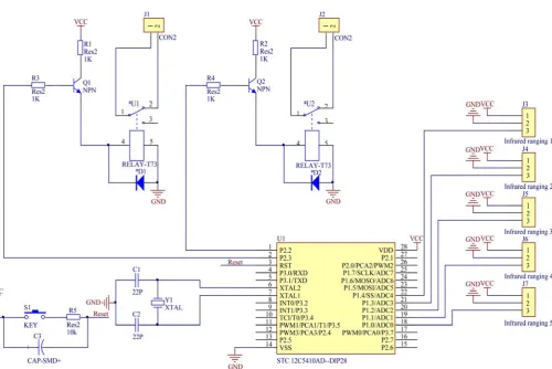
ports with relay switches to output the control signal, as shown in Figure 2. The installation structure of the soil surface height variation information acquisition system, which is schematized in Figure 3, contains the ranging sensor group and the sensor mounting assembly. The main technical parameters of the system are as follows: response time: 0.03 s; height measurement range: 20-500 mm; and accuracy within the measurement range: ±1 mm.
Figure 1 Height information acquisition device structure block diagram
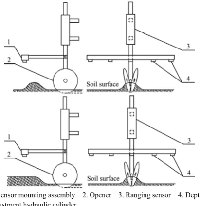
1. Sensor mounting assembly 2. Opener 3. Ranging sensor 4. Depth- adjustment hydraulic cylinder
Figure 3 Simplified diagram of the installation structure of the highly variable acquisition device
2.1.2 Working principle
Before running the system, the initial position of the ranging sensor relative to the soil surface height is set on the MCU, and when measuring, the soil surface height variation measurement mechanism fluctuates vertically with the changing surface topography and provides a baseline for furrowing depth; when the distance change acquired by the sensor directly in front of the opener exceeds the reasonable range, the MCU compares the numerical information collected by the main sensor with the information collected by the other auxiliary sensors and finds the cause of the change in the ranging distance detected by the sensor directly in front of the opener through a difference analysis. When the change is caused by the surface height variation, the MCU operates in response to the change and exports a profiling control signal; otherwise, the change is deemed invalid, and profiling control is not performed.
2.2 Design of key components
2.2.1 Sensor selection
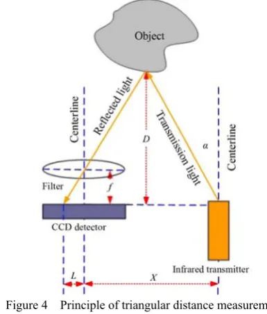
The methods for noncontact active ranging include laser, radar, ultrasonic, infrared light, and continuous wave radar[32-44]. Relative to ultrasonic waves, infrared waves transmit faster with better transmission directivity, higher transmission power controllability, and greater robustness against interference[45-50]. Therefore, an infrared ranging sensor was chosen in this study to measure the distance using the triangulation method (Figure 4)[51]. The principle of infrared ranging is that an infrared transmitter transmits an infrared beam in a certain angle and that the beam returns when encountering an object; the reflected light is collected by the CCD detector with a shift value, through which, together with the known emission angle a, the central distance (X), and the filter focal length f, the distance between the sensor and the object (D) can be calculated through the triangle geometry. Because of the principle of triangulation, the scanning range of the sensor measurement is not a plane but a point, so an array of sensors is needed to work in concert to achieve the goal of accessing ground interval changes. 2.2.2 Determination of the sensor position and quantity
Following tillage, the maximum diameter of the clod is smaller than 50 mm[52]. When the conservation tillage is practiced, corn stalks are shredded and returned to the field; the average length of the corn stalk shreds is 52 mm, while the incompletely shredded corn stalks are 100-250 mm in length[53]. When acquiring the surface distance information, the presence of clods or corn stalks in the ranging area of the sensor may cause inconsistencies between the surface height variation information and the actual situation, resulting in profiling control errors. By adopting the real-time mult-isensor data comparison method, we can mitigate the interference of debris on soil surface contour information acquisition and thus reduce such errors.
Figure 4 Principle of triangular distance measurement To accommodate the presence of incompletely shredded stalk pieces in the ranging areas of all the sensors and to avoid the possibility that the actual soil surface height variation information is not acquired by any sensor, the spacing between the sensor should be larger than the diameter of the incompletely tilled clods, and the maximal ranging area of the soil surface height variation information acquisition component should be larger than the maximal length of the incompletely shredded corn stalk (250 mm). Consequently, five infrared ranging sensors are used in the acquisition assembly perpendicular to the moving direction of the planter, with a spacing of 70 mm between the sensors and a ranging width of 280 mm (Figures 5 and 6); the sensor in the center shares the same longitudinal trajectory as the opener.
1. Electronic mounting board 2. Infrared ranging sensor Figure 5 Locations of the infrared distance sensors
Figure 6 Infrared ranging sensor group 2.2.3 Nonessential profiling control principle
signal of each of the four adjacent sensors to determine whether to profile, and if it is necessary to profile, then the profiling is performed with the profiling control according to the soil surface height variation data acquired by the main sensor. The possible scenarios of the surface height variation detected by the main sensor are analyzed to determine the necessary profiling control scheme.
In different ground conditions, the surface height variation information collected by each sensor varies, and the profiling decisions are also different. 1) The system selects profiling control when the field surface is uniformly level, the soil surface height variation is uniform, and the difference between the change in the soil surface height variation acquired by the main sensor and that of each of the remaining four sensors is lower than 5 mm. 2) The system selects profiling control when the sowing field is the furrowed land after the tillage, in which the height at each ranging point within the ranging width varies, the changes sensed by the sensors while advancing are consistent, and the distance information acquired by the main sensor is continuous, with values fluctuating within a reasonable excursion of ≤5 mm. 3) In cases of small bumps and depressions of soil surface height, clods, or exposed or partially exposed corn stalks, if the main sensor senses the height variation while the auxiliary sensors sense only slight or no variation, the system decides against performing profiling control. 4) If the field is unleveled, and the heights measured by the five sensors are different, the system makes the decision on profiling control based on the duration of the continuously changing signals acquired by the main sensor. When the opener encounters an extended bump or depression, i.e., the duration of the height changing signal is ≥0.1 s, the system makes the decision of performing profiling control; otherwise, the system decides against profiling control.
As shown in Figure 7, the signal change information acquired by the sensor group when the opener is aligned with the furrow after tillage is similar to that acquired in the cases of small bumps and depressions of soil surface height, clods, and exposed or partially exposed corn stalks; the difference is that the former is continuous. To distinguish the two ground conditions, the timing of the information acquisition of the main sensor is performed, in which the timing on the signal from the main sensor is started when the soil surface height variation information is acquired by the main sensor and its difference from that of each of the other four sensors is greater than a reasonable value; when the duration is longer than the set time, profiling control is performed, otherwise, profiling control is not performed. The speed of the corn seeding operation is generally 5-8 km/h, and the planting spacing is 20-25 cm, so the average time interval between sowing two seeds is 0.4 s, and the timing duration of 0.1 s is set (during which the planter advances a distance of 139-222 mm). Based on the characteristics of change in the signal acquired by each of the sensors at different soil surface height variations, the profiling control program is designed, as shown in Figure 8.
1. Sensor mounting assembly 2. Opener 3. Ranging sensor 4. Depth- adjustment hydraulic cylinder
Figure 7 Surface small soil bags and ribbon deployment
Figure 8 Surface small soil bags and ribbon deployment
2.3 Experiment methods
2.3.1 Test equipment
The nonessential profiling control tests were performed on the soil surface height information acquiring platform (the platform moved along the rail of the soil bin through wheels to ensure the constant level of the sensor group during the test, and the distance between the ranging sensor group and the ground was 350 mm), which was connected to the soil bin test vehicle that was used to supply the pulling force, as shown in Figure 9.
2.3.2 Preparations before the test
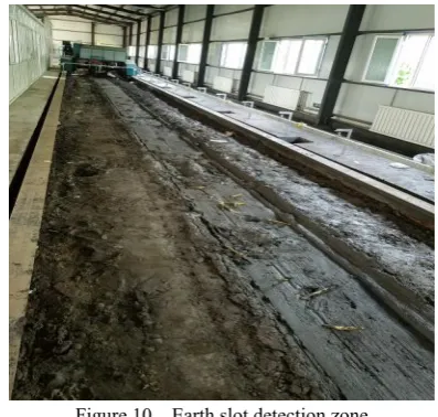
Before the test, the soil in the soil bin was leveled, and various levels of raised and lowered surfaces (No. 1-6), bumps and potholes (No. 7-10), and furrow areas (No. 11-12) were incorporated in addition to debris sites with clods and incompletely shredded corn stalks (soil measurement sites: No. 13-16; stalk measurement sites: No. 17-26). The metal modules of proximity sensors were mounted on the side of the rail parallel to the test sites for positioning; the soil bin test platform is shown in Figure 10.
Figure 10 Earth slot detection zone 2.3.3 Test content
In the static state, the decision-making ability of the soil surface height variation information acquisition system was tested in the presence of potholes, bumps, clods, and corn stalk pieces
when profiling control is not needed. At the upper speed limit of the corn sowing operation (8 km/h), the furrow area measurement accuracy and the profiling control decision-making accuracy were examined.
3 Results and discussion
3.1 Nonessential profiling control test and results
The designed multipoint surface height variation information acquisition system was tested, and the feasibility, accuracy and stability of the nonessential profiling control of the system were evaluated through static and dynamic tests.
3.2 Test results and analysis
3.2.1 Analysis of results of static measurement test
Sites 1-12 were tested in the static measurement; the soil surface height variation data and the measurement data of five tests are shown in Table 1. The errors of the five measurements were plotted on a line chart, as shown in Figure 11. The mean error of the static measurements was 1.67 mm, the standard deviation of the errors (σ) of the overall static measurement data (calculated using Equation (1)) was 1.80, and the stability of the system was 94.5%, indicating that the measurement accuracy met the system design requirements.
2 1
1
( )
N
i i
σ x μ
N =
=
∑
− (1)In the static measurements, the standard error (σ) of the overall soil surface height variation measurement data was 1.84, and the stability of the system was 93.9%; the standard error (σ) of the soil surface height variation data of the individual site and the furrow area was 2.13, and the stability of the system was 95.1%.
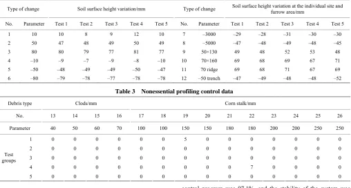
Table 1 Static measurement data
Type of change Soil surface height variation/mm Type of change Soil surface height variation at the individual site and furrow area/mm No. Parameter Test 1 Test 2 Test 3 Test 4 Test 5 No. Parameter Test 1 Test 2 Test 3 Test 4 Test 5
1 10 10 9 9 12 10 7 –30×100 –29 –28 –31 –30 –27
2 50 47 48 47 50 49 8 –50×100 –47 –48 –49 –48 –45
3 80 80 79 77 81 77 9 50×130 49 48 52 53 48
4 –10 –9 –7 –9 –8 –10 10 70×160 69 68 69 67 72
5 –50 –48 –49 –49 –50 –47 11 70 ridge 69 68 71 67 69
6 –80 –79 –78 –77 –78 –78 12 –50 trench –47 –49 –48 –48 –52
3.2.2 Analysis of the dynamic measurement test results
The dynamic measurements were performed on Sites 1-26, of which Sites 13-26 were sites to evaluate the decision making associated with profiling control. The measurements were performed at each site at a moving speed of 8 km/h (Table 2), and the errors of the set soil surface height variation data and the measurement data from five tests were plotted on a line chart, as shown in Figure 12. The measurements in the dynamic tests were similar to those in the static tests; the mean error of the measurements in the furrow area was 2.3 mm, the standard deviation σ of the dynamic measurement data was 2.77, and the stability of the system was 92.1%. In the dynamic measurements, the standard deviation of the error (σ) of overall soil surface height variation measurement data was 2.63, and the stability of the system was 93.1%; the standard error (σ) of the soil surface height variation data of the individual site and the furrow area was 2.93, and the stability of the system was 91.8%. Sites 13-26 were the sites with debris, with an expected output value of 0 mm, and
deviation from this value indicates a decision error associated with the profiling control. The nonessential profiling control data are shown in Table 3, and the results show that the accuracy of the nonessential profiling control program was 97.1% and the stability of the system was 94.1%.
Figure 12 Dynamic measurement
Based on the above analyses, the soil surface height variation information acquisition system was tested through static and dynamic measurements; the experimental methods and the system response time (0.03 s) were identical to those of Wen et al.[20] but
accuracy of sowing depth control decisions and reduced the incidence of profiling errors. Relative to traditional mechanical and contact ground detection[12,13,16], the proposed method simplified the structure while avoiding mechanical wear. The field experiments showed that in actual field operations, particularly when exposing the sensors to direct high-intensity sunlight, the sensors were occasionally interfered by the sunlight, so small visors were designed and installed near the sensor group to avoid direct sunlight.
Table 2 Dynamic measurement data
Type of change Soil surface height variation/mm Type of change Soil surface height variation at the individual site and furrow area/mm
No. Parameter Test 1 Test 2 Test 3 Test 4 Test 5 No. Parameter Test 1 Test 2 Test 3 Test 4 Test 5 1 10 10 8 9 12 10 7 –3000 –29 –28 –31 –30 –30 2 50 47 48 49 50 49 8 –5000 –47 –48 –49 –48 –45
3 80 80 79 77 81 77 9 50×130 49 48 52 53 48
4 –10 –9 –7 –9 –8 –10 10 70×160 69 68 69 67 71
5 –50 –48 –49 –49 –50 –47 11 70 ridge 69 68 71 67 69
6 –80 –79 –78 –77 –78 –78 12 –50 trench –47 –49 –48 –48 –52
Table 3 Nonessential profiling control data
Debris type Clods/mm Corn stalk/mm
No. 13 14 15 16 17 18 19 20 21 22 23 24 25 26
Parameter 40 50 60 70 100 100 150 150 180 180 200 200 250 250
1 0 0 0 0 0 0 5 0 0 0 0 0 0 0 2 0 0 0 0 0 0 0 0 0 0 0 0 0 0 3 0 0 0 0 0 0 0 0 0 0 0 0 0 0 4 0 0 0 0 0 0 0 0 0 7 0 0 0 0 Test
groups
5 0 0 0 0 0 0 0 0 0 0 0 0 0 0
4 Conclusions
In this study, we designed a multipoint surface height variation information acquisition system for the profiling mechanism of the seeding unit of a corn planter; the response time and height measurement range of the system were 0.03 s and 20-500 mm, respectively. The system provides nonessential profiling control, reduces the incidence of profiling error due to the interference of ground debris on the system, and provides a reference for the design of a surface height variation information acquisition system.
1) The measurement accuracy of the surface height variation information acquisition system was 3 mm. The standard error σ
of the overall soil surface height variation measurement data was 2.63, and the stability of the system was 93.1%. The standard deviation σ of the errors of surface height variation of the individual site and furrow area was 2.93, and the stability of the system was 91.8%.
2) When acquiring the soil surface height information at a moving speed of 8 km/h, the accuracy of the nonessential profiling
control program was 97.1%, and the stability of the system was 94.1%.
Acknowledgments
This study was financially supported by the Special Funding Project for Public Welfare Industries (Agriculture) Scientific Research: Research on Mechanized Cultivation Model in Maize Planting Area of State Farm (201503116-04-04) and conducted in the Conservation Tillage Technology Center of the Heilongjiang Provincial Education Department jointly established by both corporations and universities.
[References]
[1] Li B F. Agricultural mechanics. China Agricultural Press, 2003; pp.48–71. (in Chinese)
[2] Gupta S C, Swan J B, Schneider E C. Planting depth and tillage interactions on corn emergence. Soil Science Society of America Journal, 1988; 52(4): 1122–1127.
59(1-2): 33–44.
[4] Yao Z L, Gao H W, Wang X Y. Effect of three furrow openers for no-till wheat seeder on crop growth performance. Transactions of the CSAE, 2007; 23(7): 117–121. (in Chinese)
[5] Loeppky H, Lafond G P, Fowler D B. Seeding depth in relation to plant development, winter survival, and yield of no-till winter wheat. Agronomy Journal, 1989; 81(1): 125–129.
[6] Zhang R, Cui T, Yin X W, Zhang D X, Li K H, Han D D, et al. Design of depth-control planting unit with single-side gauge wheel for no-till maize precision planter. Int J Agric & Biol Eng, 2016; 9(6): 56–64.
[7] Patwardhan R G, Rans M J. Planter with depth adjustment mechanism: U.S. Patent 7,946,232. 2011-5-24.
[8] Lyu B, Yang Y Q, Liu H J, Cao X Z, Zhou Y, Zhao S H. Design and experiment on twin-row soybean no-till planter. Soybean Science, 2015; 34(6): 1047–1052.
[9] Ozmerzi A, Karayel D, Topakci M. Effect of sowing depth on precision seeder uniformity. Biosystems Engineering, 2002; 82: 227–230. [10] Cai G H, Li H, Li H W, Wang Q J, He J, Ni J L. Design of test-bed for
automatic depth of furrow opening control system based on ATmega128 single chip microcomputer. Transactions of the CSAE, 2011; 27(10): 11–16. (in Chinese)
[11] Hu J. Theory and experimental research of sowing depth control for precision seeder unit. Changchun: Jilin University, 2012. (in Chinese) [12] Li Y H, Meng P X, Geng D Y, He K, Meng F H, Jiang M. Intelligent
system for adjusting and controlling corn seeding depth. Transactions of the CSAM, 2016; 47(S1): 62–68+42. (in Chinese)
[13] Nan C L. Research of potato digger digging blade electro-hydraulic profile modeling system. Inner Mongolia Agriculture University, 2013. (in Chinese)
[14] Hernández Á, Ureña J, García J J, Mazo M, Hernanz D, Dérutin J P, et al. Ultrasonic ranging sensor using simultaneous emissions from different transducers. IEEE Transactions on Ultrasonics, Ferroelectrics and Frequency Control, 2004; 51(12): 1660–1670.
[15] David S M, Ernesto M G, José L G. Multipath mitigation for a phase-based infrared ranging system applied to indoor positioning. IEEE International Conference on Indoor Positioning and Indoor Navigation (IPIN), 2013.
[16] Liu L J, Yang X J, Li C R. Design of 2BMG-24 no-till wheat planter. Transactions of the CSAM, 2009; 40(10): 39–43. (in Chinese)
[17] Lin J, Liu A D, Li B F. 2BG-2 type corn ridge planting no-till planter. Transactions of the CSAM, 2011; 42(6): 43–46. (in Chinese)
[18] Liu H X, Guo L F, Fu L L, Tang S F. Study on multi-size seed-metering device for vertical plate soybean precision planter. Int J Agric & Biol Eng, 2015; 8(1): 1–8. (in Chinese)
[19] Lin Y X, Shang S Q, Wang D W, Cui Z C, Yang H G. Design and experiment of inclined inserted no-tillage hill seeder. Transactions of the CSAE, 2017; 33(23): 8–14. (in Chinese)
[20] Yao Z L, Li H W, Gao H W. Experiment on no-till wheat planter under the bestrow of the maize stubble in double cropping area. Transactions of the CSAM, 2007; 38(8): 57–61. (in Chinese)
[21] Chen H, Huang H, Yang Y L. Design of row-followed no-till wheat and maize planter under controlled traffic farming system. Transactions of the CSAM, 2009; 40(3): 72–76. (in Chinese)
[22] Mouazen A M, Anthonis J, Saeys W, Ramon H. An automatic depth control system for online measurement of spatial variation in soil compaction, Part 1: Sensor design for measurement of frame height variation from soil surface. Biosystems Engineering, 2004; 89(2): 139–150. [23] Saeys W, Wallays C, Engelen K, Ramon H, Anthonis J. An automatic
depth control system for shallow slurry injection, Part 2: Control design and field validation. Biosystems Engineering, 2008; 99: 161–170. [24] Jensen L D, Nelson C, LeClaire J P. Depth control device for planting
implement: U.S. Patent 6,701,857. 2004-3-9.
[25] Anthonis J, Mouazen A M, Saeys W, Ramon H. An automatic depth control system for online measurement of spatial variation in soil compaction, Part 3: Design of depth control system. Biosystems Engineering, 2004; 89(1): 59–67.
[26] Zhao J L, Zhu L T, Jia H L, Huang D Y, Guo M Z, Cong Y J. Automatic depth control system for a no-till seeder. Int J Agric & Biol Eng, 2018; 11(1): 115–121.
[27] Zielke R R. On-the-go soil sensors and control methods for agricultural machines: U.S. Patent Application 15/717, 296. 2018-1-18.
[28] Wen L P. The research of precision planter sowing depth control system based on PLC. Inner Mongolia Agriculture University, 2014. (in Chinese)
[29] Zhao J H, Liu L J, Yang X J, Liu Z J, Tang J X. Design and laboratory test of control system for depth of furrow opening. Transactions of the CSAE, 2015; 31(6): 35–41. (in Chinese)
[30] Gao H W, Li W Y, Li H W. Conservation tillage technology with Chinese characteristics. Transactions of the CSAE, 2002; 19(3): 1–4. (in Chinese)
[31] Zhang W, Wang C, Liang Y, Li Y Q. Effects of debris covering on soil temperature in dryland farming area. Transactions of the CSAE, 2006; 22(5): 70–73. (in Chinese)
[32] Feng G, Chang B. Study of high precision laser ranging technology. Laser & Infrared, 2007; 11: 004.
[33] Shan J, Toth C K. Topographic laser ranging and scanning: principles and processing. CRC Press, 2018.
[34] Toth C K, Petrie G. Introduction to laser ranging, profiling, and scanning. in Topographic laser ranging and scanning. CRC Press, 2018: 1–28. [35] Figueroa J F, Lamancusa J S. A method for accurate detection of time of
arrival: Analysis and design of an ultrasonic ranging system. The Journal of the Acoustical Society of America, 1992; 91(1): 486–494.
[36] Shangsong T Y C. Study on precision of ultrasonic ranging. Foreign Electronic Measurement Technology, 2006; 2: 010.
[37] Zhang K, Liu G H. Research on a method of improving ultrasonic ranging precision. Modern Electronic Technique, 2007; 15: 139–141. (in Chinese)
[38] Queiros R, Alegria F C, Girao P S, Serra A C. Cross-correlation and sine-fitting techniques for high-resolution ultrasonic ranging. IEEE Transactions on Instrumentation and Measurement, 2010; 59(12): 3227–3236.
[39] Stann B L, Ruff W C, Sztankay Z G. Intensity-modulated diode laser radar using frequency-modulation/continuous-wave ranging techniques. Optical Engineering, 1996; 35(11): 3270–3279.
[40] Xu B, Li G, Huang F K. Ambiguity problem of digitized multiple frequency CW ranging radar under noisy condition. Acta Electronica Sinica, 2002; 30(6): 903–906.
[41] Abou-Jaoude R. ACC radar sensor technology, test requirements, and test solutions. IEEE Transactions on Intelligent Transportation Systems, 2003; 4(3): 115–122.
[42] Feng G, Chang B. Study of high precision laser ranging technology. Laser & infrared, 2007, 11: 004.
[43] Mautz R. Indoor Positioning Technologies, 2012.
[44] Whiteside G D. Scene recognition method and system using brightness and ranging mapping: U.S. Patent 6,516,147. 2003–2-4.
[45] Zhang D, Xia F, Yang Z, Yao L, Zhao W H. Localization technologies for indoor human tracking. IEEE 5th International Conference on Future Information Technology (FutureTech), 2010.
[46] Scribner D A, Kruer M R, Killiany J M. Infrared focal plane array technology. Proceedings of the IEEE, 1991; 79(1): 66–85.
[47] Rogalski A. Recent progress in infrared detector technologies. Infrared Physics & Technology, 2011; 54(3): 136–154.
[48] Rogalski A, Chrzanowski K. Infrared devices and techniques. Optoelectronics Review, 2002; 10(2): 111–136.
[49] Wang L, Zou X Y, Liu S Y, Chen B L, Zhu H C, Zhu R J. Infrared distance measurement used for cotton picker robot. Transactions of the CSAM, 2014; 45(07): 61–66. (in Chinese)
[50] He X K, Zeng A J, Liu Y J, Song J L. Precision orchard sprayer based on automatically infrared target detecting and electrostatic spraying techniques. Int J Agric & Biol Eng, 2011; 4(1): 35
[51] T Q W, Qu Z Y, Zhu H Q. Design of infrared range finder system for a robot based on a single chip microcomputer. Applied Science and Technology, 2010.
[52] Liu X W. Research and development of double roller cultivation machine for straw-soil returning. China Agriculture University, 2000. (in Chinese) [53] Du C W. Development and test of a new type of maize straws rushing