Doctoral School in Materials Science and Engineering
Laser Cladding with metallic powders
Simone Zanzarin
November 2015
X
X
V
II
I c
yc
Laser cladding with metallic powder
Simone Zanzarin
E-mail: [email protected]
Approved by:
Prof. Alberto Molinari, Advisor
Department of Industrial Engineering University of Trento, Italy.Ph.D. Commission:
Prof. Antonella Motta,
Department of Industrial Engineering University of Trento, Italy.Prof. Emanuela Cerri,
Department of Industrial Engineering University of Parma, Italy.Prof. Nuno M. Neves,
Department of Polymer Engineering University of Minho, Portugal.University of Trento
Department of Industrial Engineering
University of Trento - Department of Industrial Engineering
Doctoral Thesis
Simone Zanzarin - 2015
Published in Trento (Italy) – by University of Trento
Index
Introduction
Chapter 1: Laser cladding
1.1 Introduction to laser cladding ...2
1.2 Lasers for laser cladding ...7
1.3 Laser cladding process ...9
1.3.1 Two-step laser cladding process ... 10
1.3.2 One-step laser cladding process ... 12
1.4 Process parameters in laser cladding ... 17
1.5 Clad characteristics... 20
1.5.1 Clad geometry ... 20
1.5.2 Dilution ... 20
1.5.3 Microstructure ... 21
1.5.4 Coating defects ... 23
1.5.5 Residual stresses ... 24
1.6 Energetic efficiency and productivity of laser cladding process ... 25
ii
2.2 Substrates ... 30
2.3 Laser cladding equipment ... 30
2.4 Processing parameters ... 31
2.5 Coatings characterization ... 32
2.5.1 Microhardness and hardness ... 32
2.5.2 Light Optical Microscopy (LOM) ... 32
2.5.3 Image Analysis ... 33
2.5.4 Scanning Electron Microscopy (SEM) and Energy-Dispersive X-ray Spectroscopy (EDXS) ... 33
2.5.5 X-Ray Diffraction (XRD) ... 33
2.5.6 Calorimetric experiment ... 33
2.5.7 Thermogravimetric Analysis (TGA) ... 33
2.6 Powders characterization ... 34
2.6.1 Density ... 34
2.6.2 Normal spectral absorbance ... 34
2.6.3 Differential Scanning Calorimetry (DSC) ... 34
Chapter 3: Results and discussion 3.1 Geometry ... 35
3.2 Dilution ... 44
3.3 Geometry and dilution: processing map ... 47
3.4 Material efficiency ... 48
3.5 Effect of substrate and preheating treatment on geometry and dilution models ... 52
3.6 Energetic model ... 57
3.6.2 Calculations of the power partitioning ... 64
3.7 Coatings characterization ... 70
3.7.1 Stellite1 ... 71
3.7.2 Inconel 625 ... 74
3.7.3 NiBSi ... 82
3.7.4 Stellites + WC... 90
Conclusions Appendix Appendix 1 - Carbides dissolution ... 98
Appendix 2 - Dilution... 99
Appendix 3 - Absorption coefficient of the liquid metal βs... 102
Appendix 4 - Normal spectral absorbance ... 108
Appendix 5 - Trial and error method ... 110
Appendix 6 - Melt pool temperature ... 111
1
Introduction
Laser cladding is an emerging technology in the field of surface engineering. The high energy density, versatility and selectivity of the laser beam allow the production of high quality thick metallic coatings with fusion bonding to the substrate and low dilution. The characteristics of this technology enable also its application in rapid prototyping and component repairing.
The properties and thus the quality of laser cladding coatings are extremely sensitive to the choice of the laser cladding equipment, materials and process parameters and, consequently, since they are highly sensitive to the complex of the physical phenomena occurring in the cladding process.
The definition of models for the description of the process and for the prediction of the characteristics of the coatings becomes thus fundamental.
For these reasons Höganäs AB, one of the world biggest powder manufacturer, and the Department of Industrial Engineering of the University of Trento started a cooperation to study and optimize the laser cladding process and the coating properties as a function of the powder characteristics and of the processing conditions.
With this aim, various metallic powders, and mixtures of metallic powders and hard reinforcement particles, have been employed to produce coatings with the High Power Diode Laser Cladding technology with coaxial powder injection. Three main processing parameters have been identified (laser power, scanning speed and feeding rate), and these parameters have been varied in an opportune operating window.
This PhD thesis can be divided into three parts. In the first part of the work, the influence of the powder material and the main processing parameters on geometrical features and dilution of the clads is investigated and discussed. Physical and analytical model that allow the explanation of the process and the prediction of the clad geometry and dilution is discussed. Using these models, useful tools for cladding operators and engineers are proposed.
In the second part of the work, the energetic balance of the process is presented. Energetic redistribution in laser cladding process is analysed in detail, and quantification of process efficiency and energy losses is given. The influence of the processing parameters and the chemical/physical properties of the materials is considered throughout the various experiments performed.
Chapter 1
Laser cladding
1.1 Introduction to laser cladding
Wear, together with corrosion and fatigue, are the three principal processes limiting the useful life of engineering products. They and their combined effect have annually a huge economic impact on industries since they cause maintenance, repair and material costs for part replacements as well as losses due to plant shutdowns. Moreover, to reduce and control wear and corrosion is important for other reasons, such as to extend the lifetime of machinery and bio-system, to make devices more efficient, to conserve poor material resources, to save energy and to improve safety. For these reasons, methods of reducing degradative phenomena have always been under development.
Historically these aims have been achieved in different ways: by design variations, selecting improved bulk materials or altering the material by alloying, by utilizing lubrication techniques to prevent wear, by changing the environment through desiccation and use of inhibitors or by cathodic and anodic protection against corrosion [1-3].
A possible solution to reduce wear, corrosion or fatigue is given by the field of surface engineering, which includes surface modification, alloying and coating methods. Surface is widely recognized as the most important part in many engineering components, since at the surface most failures originate, either by wear, fatigue or corrosion. Application of wear/corrosion-resistant coatings is up to now one of the most widely used means of protecting components, and has the advantage of changing the chemical composition of the surface. This allows designing composite systems made of coating and substrate having particular features:
multi-material structures having performances which cannot be achieved by either the coating or the substrate alone (for instance, thermal barrier coatings);
systems able to provide resistance against given service conditions having cheap and less noble base materials and more expensive and nobler coating alloys on the surface [1,2,4-7].
Chapter 1 – Laser cladding
3
Figure 1.1. Classification of surface engineering techniques depending on the state of the depositing phase [5].
Another common way to classify these methods is based on the coating thickness they can produce: for instance, ion implantation, ion assisted coating, electroless and electrolytic plating, chemical and physical vapour deposition are common methods to produce thin films of a few micron thickness, whereas thermal and cold spraying, friction surfacing, electrochemical plating and overlay welding are representative methods to manufacture thicker coatings, having thicknesses ranging from a few hundred microns up to several millimetres (Figure 1.2).
This distinction is important to ensure the optimum performance of the coating: for instance, intense mechanical stresses are critical for thin layer, whereas they may be adequate to decrease friction coefficient and to resist corrosion and some form of wear; thick protective layers are usually preferred for high surface stress conditions or intense wear [1,2,5,7-9].
Belonging to the latter group, laser cladding has recently gained an increased importance in a variety of industrial sectors such as automotive, aerospace, navy, defence and many others.
Similar to overlay welding, laser cladding is a coating technique where a laser heat source is utilized to fuse and deposit a layer of a selected material on a substrate in order to form a defect-free protective coating, fusion bonded to the base material, with maximum coating material efficiency and minimum dilution (i.e. contamination due to the substrate material that has been melted and has mixed with the clad). The additive material can be deposited to the substrate by several methods: in form of powder or paste, that can be either injected during the process or pre-placed, or by wire/strip feeding. The process can be schematically described as follows: the laser beam scans the surface creating a melt pool with the fused coating material and, partially, the substrate material. Once laser irradiation stops or laser moves, solidification occur due to rapid heat transfer to the bulk and the coating is formed. During the process, a shielding gas is always used to protect the molten material from the atmosphere [8-12]. Compared to the conventional heat sources, the use of the laser allows to reach orders of magnitude higher energy densities, because a highly concentrated optical energy can be sharply focused on a well-confined zone of the surface of the base material. Owing to these characteristics, a very thin layer of base material is melted together with the coating material leading simultaneously to a controlled minimal dilution by the substrate and nevertheless a very strong fusion bonding between substrate and coating, which is a unique feature of laser cladding. The fusion bonding, together with the epitaxial growth of the coating microstructure from the substrate, guarantee excellent adherence. The use of a laser source causes other benefits: high energy density of the laser allows short interaction times between heat source and base material, leading to high solidification and cooling rates. High solidification and cooling rates generate fine grained microstructures which frequently contain non-equilibrium phases and supersaturated solid solutions, and limit both microsegregation and dissolution of externally added reinforcements. Distortion and metallurgical changes of the substrate are reduced due to the low heat input into the base material. Since the laser energy is applied locally, laser cladding is well-suited to the treatment of small areas, to repair tooling (especially on critical contacting surfaces), to produce functionally graded parts (for instance, thermal barrier coatings) by injecting different materials during the fabrication, and to create “smart structures” by embedding objects such as sensor and magnets during production [8,9,11,12].
Despite its advantages over conventional fabrication technologies, laser cladding presents also some drawbacks: the combination of the highly concentrated energy of the laser and high scanning speed generates strong thermal gradients, which make the production of crack-free coating with brittle material quite a hard task, due to generation of tensile residual stresses on the coating. Other disadvantages are the limited energetic efficiency of the cladding process due to the high reflection of laser light from the metallic melt pool surface, the high investment costs of the laser equipment and the lack of control over the cladding process, which is given by the high sensitivity of laser cladding to small changes in the operating parameters as well as to process disturbances [8,9,11,12].
Chapter 1 – Laser cladding
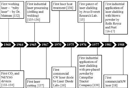
5 number of publications and patents regarding laser cladding in different forms (with wires, rods and pre-placed powders, with dynamical feed of wires and, few years later, with powder feeding) began to grow. Industry started to utilize laser cladding in early-80’s: the first reported uses were hard-facing of Nimonic turbine blade interlock shrouds for the RB-211 jet engine at Rolls Royce (1981) and of nickel-base alloy turbines of JT8 and JT9 engines at Pratt and Whitney (1983) [14-17]. In the following years laser cladding technology was introduced in the automotive industry by companies such as Fiat, Toyota and Mercedes Benz for the engine valve seat coating, and was also used in components repair market (to re-build worn turbine vanes, tip of turbine blades and turbine bolts) and in rapid prototyping process (stereo lithography) [11]. Some important milestones in laser and laser cladding technology are reported in Figure 1.3.
Figure 1.3. Important milestones in laser cladding.
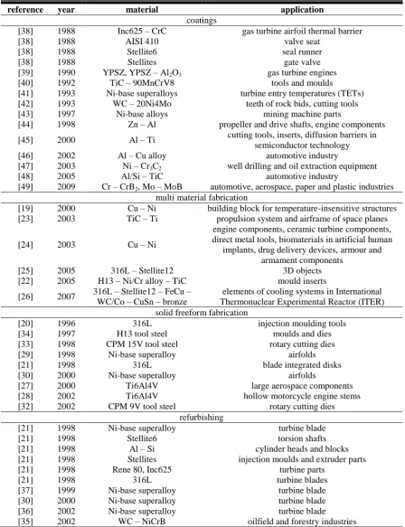
Nowadays, laser cladding applications are the production of surface coatings, the production of entire components (rapid prototyping and tooling) and the repair and the refurbishment of damaged parts (Table 1.1).
Table 1.1. Industrial applications of laser cladding.
reference year material application
coatings
[38] 1988 Inc625 – CrC gas turbine airfoil thermal barrier
[38] 1988 AISI 410 valve seat
[38] 1988 Stellite6 seal runner
[38] 1988 Stellites gate valve
[39] 1990 YPSZ, YPSZ – Al2O3 gas turbine engines
[40] 1992 TiC – 90MnCrV8 tools and moulds
[41] 1993 Ni-base superalloys turbine entry temperatures (TETs) [42] 1993 WC – 20Ni4Mo teeth of rock bids, cutting tools
[43] 1997 Ni-base alloys mining machine parts
[44] 1998 Zn – Al propeller and drive shafts, engine components [45] 2000 Al – Ti cutting tools, inserts, diffusion barriers in
semiconductor technology
[46] 2002 Al – Cu alloy automotive industry
[47] 2003 Ni – Cr3C2 well drilling and oil extraction equipment
[48] 2005 Al/Si – TiC automotive industry
[49] 2009 Cr – CrB2, Mo – MoB automotive, aerospace, paper and plastic industries
multi material fabrication
[19] 2000 Cu – Ni building block for temperature-insensitive structures [23] 2003 TiC – Ti propulsion system and airframe of space planes
[24] 2003 Cu – Ni
engine components, ceramic turbine components, direct metal tools, biomaterials in artificial human
implants, drug delivery devices, armour and armament components
[25] 2005 316L – Stellite12 3D objects
[22] 2005 H13 – Ni/Cr alloy – TiC mould inserts
[26] 2007 316L – Stellite12 – FeCu – WC/Co – CuSn – bronze
elements of cooling systems in International Thermonuclear Experimental Reactor (ITER) solid freeform fabrication
[20] 1996 316L injection moulding tools
[34] 1997 H13 tool steel moulds and dies
[33] 1998 CPM 15V tool steel rotary cutting dies
[29] 1998 Ni-base superalloy airfolds
[21] 1998 316L blade integrated disks
[30] 2000 Ni-base superalloy airfolds
[27] 2000 Ti6Al4V large aerospace components
[28] 2002 Ti6Al4V hollow motorcycle engine stems
[32] 2002 CPM 9V tool steel rotary cutting dies
refurbishing
[21] 1998 Ni-base superalloy turbine blade
[21] 1998 Stellite6 torsion shafts
[21] 1998 Al – Si cylinder heads and blocks
[21] 1998 Stellites injection moulds and extruder parts
[21] 1998 Rene 80, Inc625 turbine parts
[21] 1998 316L turbine blades
[37] 1999 Ni-base superalloy turbine blade
[30] 2000 Ni-base superalloy turbine blade
[36] 2002 Ni-base superalloy turbine blade
Chapter 1 – Laser cladding
7 The leading metallic coating application is the coating of commercial aircraft gas turbines. It has been used also in the sector of spacecraft components and for the production of surfaces for industrial parts, such as shafts used in drilling tools, engine valve seats, tool hardfacing, hydraulic pump components and moulds [11]. Multi-material fabrication has also been achieved with laser cladding process: examples of produced functionally graded materials with special functionalities are structure with overall negative coefficient of thermal expansion, injection moulding tools with embedded copper heat sink and other particular structures [19-26]. Regarding the solid freeform fabrication, different types of components, ranging from thin-walled structure to highly complex bulk objects, have been produced, including large aerospace components, hip implants and hollow motorcycle engine steams, airfoils, injection moulding tools, blade integrated disks, injection moulding dies and rotary cutting dies [20,21,27-34]. Parts repair and refurbishing, which is one of the major application of laser cladding, has been principally done on damaged turbine blades. Other repaired components with this technique are moulds and engine cylinder heads and blocks [30,31,35-37].
1.2 Lasers for laser cladding
Laser materials processing involves a broad range of power densities, interaction times and transport phenomena. Figure 1.4 presents operational regimes and associated transport phenomena for various processing techniques, [50-52].
Figure 1.4. Process map for various laser applications in materials processing [50].
(HPDL). In the last decade, fibre laser have also been adopted. Table 1.2 summarizes the most important characteristics of the commonly used laser in laser cladding [11,53-56].
Table 1.2. Important characteristics of the commonly used laser in laser cladding.
characteristics CO2 lamp-pumpedNd:YAG diode-pumpedNd:YAG HPDL fibre
wavelength
[μm] 10.64 1.06 1.06 0.65 – 0.94 0.34 – 2.10
wall-plug efficiency
[%] 5 – 10 1 – 4 10 – 12 > 50 > 30
maximum power
[kW] 45 4 5 15 50
average power density
[W/cm2] 10
6 – 108 105 – 107 106 – 109 103 – 105 106 – 1010 service period
[hour] 1000 – 2000 200 5000 - 10000 5000 - 10000 100000
beam parameter product
[mm∙mrad] 12 25-45 12 100 – 1000 0.3 – 1.1
fibre coupling no yes yes yes yes
CO2 lasers are relatively inexpensive. They have good beam quality, which is expressed by the low
value of the beam parameter product (BPP), and can provide very high power. The principal drawback of CO2 lasers is the light emission wavelength (10.64 μm), that is longer than the wavelength of
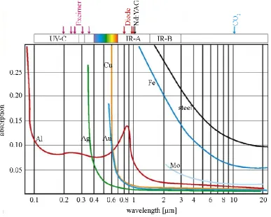
Nd:YAG and HPDL light: this causes technological and economical limits. As shown in Figure 1.5, the interaction between metals and the laser light is function of the laser wavelength: in specific, metals are less absorptive at 10 μm than at 1 μm.
Chapter 1 – Laser cladding
9 This leads to a limited energetic efficiency of the process (5 – 25%). Moreover, due to its wavelength the laser beam delivery through a fibre optic cable is not possible. As a result, the manoeuvrability of a motion system along with a CO2 laser is limited and its use for the production of complex part is
restricted [11,57].
Nd:YAG solid-state lasers have shorter wavelength (1.06 μm). Lamp-pumped Nd:YAG laser is a relatively inexpensive type of laser with a power range up to 4 kW. In comparison with CO2 lasers,
fibre-coupling is possible, and the energy absorption by the metallic melts reaches values up to 60%. The disadvantages regarding efficiency and beam quality have been solved by another type of Nd:YAG solid-state laser, using laser diodes for excitation. The wall-plug efficiency of diode-pumped Nd:YAG lasers ranges from 10% to 12%, and the beam quality is also improved considerably. The technical parameters of these systems correspond to those of the CO2 laser, but with the advantage of
the fibre-coupling and the improved absorption. The main disadvantage of the diode-pumped Nd:YAG laser is the significantly higher price compared to CO2 laser [11,57].
High power diode lasers (HPDL) are particularly compact and with their characteristic hat profile of power distribution, they are tailored for laser cladding applications. HPDL beam has low beam quality, but its cross-section can have different shapes (round, rectangular and linear). Both the wall-plug efficiency and the energy absorption by the melt-pool can be higher than 50%. Compared to a same power output CO2 laser, the deposition rate can be higher. [58]. Since the costs per kilowatt of
laser power are much lower compared to those of the diode-pumped Nd:YAG and the CO2 lasers, high
power diode lasers are the preferred tool for laser cladding.
The latest generation of lasers are fibre lasers. These solid-state laser are in the power range up to 50 kW and their features are high beam quality and a focus diameter of about 10 μm, high brightness, irradiation mode easy to pulse, high efficiency and moderate investment costs [57].
1.3 Laser cladding process
As discussed in the previous paragraph the interaction between laser and material leads to different processes (Figure 1.6).
Laser transformation hardening, laser remelting, laser welding and laser shock hardening are based on a microstructural change of the surface layer. Alternatively, in laser cladding and alloying the addition of the coating material to the melt pool generates a coating layer called “clad” with a different chemical composition on the top of the base material. Chemical composition and features of the clad depend on type and amount of material added, as it can be seen in Figure 1.7.
Figure 1.7. Different microstructures and chemical compositions of laser alloying, glazing, and cladding [11].
In laser alloying, only a small amount of filler material is fed into the melt pool. For this reason, a complete and homogeneous mixing of additive and base material throughout the melt region is achieved. Laser cladding is similar to laser alloying, except that dilution by the substrate is minimized and much more addition of filler material to the substrate surface is required. The additive material can be deposited to the substrate principally by two methods: by fusing the additive material already pre-placed on the surface of the base material (two-step process) or by feeding it dynamically to the laser-generated melt pool (one-step process) (Figure 1.8).
Figure 1.8. Different methods of laser cladding: (a) two-step laser cladding, (b) one-step laser cladding with (b1) paste, (b2) powder injection and (b3) wire feeding [11].
1.3.1 Two-step laser cladding process
Chapter 1 – Laser cladding
11 chip, strip or foil, etcetera [8,11]. Among these, laser cladding with preplaced powder is one of the simplest and most common method [51]. Powders are usually applied in form of slurry made of powder, water and a binder, which is often an alcohol (for instance PVA). The purpose is to guarantee both powder agglomeration and a good bonding between the pre-placed powder layer and the substrate. This prevent the removal of the powder particles due to the inert gas flowing during the second step of the process and thus ensures the good quality of the final coating. Water and organic binder evaporate by drying process at elevated temperature and by laser melting process respectively. This may cause porosity in the final coating [8]. Alternatively, powder pre-placing can be accomplished by some conventional coating technique such us thermal spraying or electroplating [8]. The physical process of laser cladding with pre-placed powder has been widely described in literature [51,59-61]. As shown by Powell [60], when laser irradiation begins the surface powder particles start to heat up, but no heat conduction is allowed between particles due to the limited interparticle contact. Subsequently, the irradiated particles melt and, in the molten state, they can conduct heat to the neighbouring particles: this allows the molten front to propagate through the insulating powder layer (Figure 1.9,a). Once the melt touches and wets the substrate (Figure 1.9,b,c,d), the chilling effect of the substrate leads to a reversal in the melt front propagation. As a result, solidification of the melt begins (Figure 1.9,e) but the melt-liquid interface does not propagate into the body of the substrate unless additional laser power and/or interaction time are provided. If the laser source continues to irradiate the surface of the melt, the energy delivered might be enough to move the melt-solid interface back down through the clad layer and across into the body of the substrate (Figure 1.9,f) [61]. The final depth of the melt front is thus representative of the dilution of the cladding material.
Figure 1.9. Contact history between melt, powder and substrate [61].
Figure 1.10. Movement of molten front with time at various laser powers [60].
1.3.2 One-step laser cladding process
In the one-step laser cladding process the precursor material is fed dynamically into the melt pool generated by the laser source. The simultaneous movement of the laser source and of the feeding system (or, alternatively, the movement of the base material) leads to the formation of the coating. Large areas or complex 3D-structures can be treated by the overlap of several beads to create a layer and by the application of consecutive layers on top of each other respectively.
Precursor material is usually in form of powder, but wire feeding, strip feeding or hybrid process are also possible.
One-step laser cladding process with powder feeding
Laser cladding with powder feeding is the most diffused one-step method due to the wide range of materials and alloys available in form of powder and to the good coupling efficiency between powder itself and laser beam [8]. In a typical blown powder laser cladding equipment (Figure 1.11), three main components are present: the laser system, the computer numerically controlled (CNC) robotic system and the powder delivery system [62].
Chapter 1 – Laser cladding
13
Figure 1.11. Typical blown powder laser cladding equipment with (a) coaxial nozzle and (b) lateral nozzle [11].
The CNC robotic system ensures the relative movement of the component and of the laser beam. Two possible configuration exist: either the specimen is fixed and the laser head, together with the feeding system, move thanks to a robot arm coupling; alternatively, the specimen is clumped to a CNC-table which moves relative to the laser-powder delivery system [62].
The powder feeding system must be capable of delivering the proper amount of powder to the interaction zone produced by the laser. The powder may be delivered by gravity or by a gas pressurized system. The latter is preferred since it allows cladding in any orientation and prevents oxidation: in fact, together with the carrier gas, a shielding gas such as helium or argon is delivered to the cladding zone to protect the molten pool from the atmosphere.
The process starts with the laser beam, which irradiates a thin layer of substrate to form a melt pool. Subsequently, powder is injected into the cladding zone, is captured by the melt pool and melts. After this, the laser-powder delivery system continues its path: the melt pool begins the solidification process along the steepest thermal gradient and clad starts to form.
The condition that determines whether the delivered powder sticks to the cladding zone to form the clad or not is defined by the type of impact. The possible types of impact are listed below, and are influenced by the laser energy absorption by the substrate and the powder particles:
solid powder – solid surface: both the powder and the substrate do not absorb enough laser energy to melt and remain in a solid-state. The powder particle is deflected and get lost.
solid powder – liquid surface: the powder particle, which doesn’t absorb enough energy to
melt, is captured by the molten pool formed.
liquid powder – solid surface: the powder particle melts during injection and sticks to the solid
surface of the substrate leading to powder catchment.
The catchment efficiency depends mostly on the formation of the melt pool, which allows the catchment of the powder particles injected [11,64-66]. In particular, material efficiency is strongly dependent on the melt pool dimension relative to the dimension of the impact area of the powder stream [8,67,68]. In general, material efficiency of the one-step laser cladding process with powder feeding is low, especially when compared to that of the two-step process, and remains the main disadvantage of this technique. Values reported in literature usually range between 40 and 80%. Some works report the possibility to increase material efficiency and productivity by using finer grade powder (< 53 μm)[10,69], with the additional benefit of the lower surface roughness of the final coating. Nevertheless, the use of fine powders increases the risk of vaporization and aerosol emission in the working room[70,71]; moreover the injection of these powder, that remains a critical aspect of this technology, may be compromised due to powder agglomeration and problems in powder flow in powder feeders and cladding nozzles.
The element that strongly characterizes the blown powder technique, as it can be seen in Figure 1.11, is the powder feeding system. Powder feeding can be performed in two ways: off-axially, also known as lateral feeding, and coaxially.
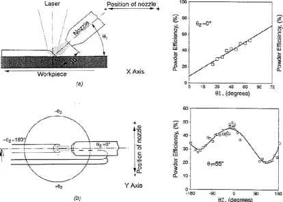
The off-axis nozzle provides a better powder catchment efficiency than the coaxial nozzle. Since the geometry and the alignment of the nozzle influences the material efficiency, as stated by Marsden [72], powder efficiency can be further increased by using a rather high injection angle between horizontal and nozzle (Figure1.12).
Figure 1.12. Schematic of blown powder laser cladding showing (a) the longitudinal section with the inclination θ1 and its influence on the powder efficiency and (b) a plan view of the clad surface with the orientation θ2 and
its influence on the powder efficiency [67].
Chapter 1 – Laser cladding
15 can be controlled in order to ensure the proper heating of the powder or, in case of externally added hard reinforcements, to avoid their dissolution. The main drawbacks of the off-axis feeding system is the low reproducibility of the process, since small variation in the nozzle location leads to substantial variation in clad geometry, dilution and powder efficiency, and the dependence of the process on the cladding direction.
In coaxial feeding process, powders are injected by a cone-shaped powder nozzle which surrounds the laser beam (Figure 1.11). This configuration allows the system to be independent on the cladding direction. In addition, powder-beam interaction time is rather long (longer than in off-axis cladding), leading to a more efficient preheating of the powder particles during their travel. Energetic efficiency of the process, as a consequence, is expected to be higher in the coaxial process due to the longer interaction times and multiple reflections occurring in the powder cloud [8].
One-step laser cladding process with wire/strip feeding
In this technology, a wire or a strip is dynamically fed into the cladding system to form the coating. There are two possible methods the wire can be melted: in the first method, the laser beam heats the wire extremity which melts and form a metal liquid droplet; the droplet falls on the component surface to form the cladding bead (Figure 1.13,a). This set-up, however, works rather erratically and generates coatings with irregular surface aspect. In the second method the wire is directly fed into the melt pool generated on the component surface by the laser beam, and melting of the wire occurs inside the melt pool by conduction (Figure 1.13,b) [73]. In this case, wire alignment becomes fundamental [74].
Figure 1.13. Schematic of laser cladding with wire/strip feeding in (a) drop by drop configuration and (b) classical configuration [73].
As discussed, feeding direction, feeding angles and tip position of the wire play a key role in this process and are thus subject of many scientific articles. Wire can be fed from a leading direction (Figure 1.14,a), from a trailing direction (Figure 1.14,b) or from the side (Figure 1.14,c) [75].
Figure 1.14. Additive wire feeding directions: (A) trailing, (B) side and (C) leading [74].
Feeding angle between wire and horizontal plane and wire tip position with respect to the melt pool can also be varied as shown in Figure 1.15.
Figure 1.15. Possibilities of wire feed angles and positions: (a) leading wire, (b) trailing wire, (c) wire tip not crossing the melt pool (d) wire tip in central position (e) wire tip crossing the melt pool [74].
Most of the authors suggest the use of the wire feeding from a leading direction, with a rather small feeding angle and the wire tip placed at the leading edge [73,76-78].
Regarding strip feeding, the only difference between this technology and wire feeding is the better coupling efficiency of the flat surface of the strip with the laser beam when compared to the cylindrical surface of the wire. This can lead to higher energetic efficiencies and deposition rates of the process [79].
Hybrid laser cladding process
In the hybrid laser cladding technology, an additional heat source is utilized together with the typical cladding set-up to supply extra energy to the process. This surplus of energy, that can be supplied to the additive material and/or to the base material, is used to increase productivity (kg/h) and deposition rate (m2/h), to decrease the laser energy required or to produce better coatings.
Chapter 1 – Laser cladding
17 feeding it into the melt pool. Different works report the advantages of this hybrid process: heated wires allow to obtain the same process productivity using a lower laser heat input (i.e. lower laser power and/or higher scanning speed) [80], and to achieve higher deposition rates [81,82].
Base material heating is generally used when cladding with brittle hardfacing alloys with the purpose to decrease the steep thermal gradients created during the process thus forming crack-free coatings. An efficient and utilized method to perform base material heating is by means of induction. Examples of the production of crack-free metal matrix composites (MMCs) clad layers [83] with simultaneous increase in deposition rates [83,84] by using induction heater on base material are presented in literature.
Other possible hybrid processes include the use of combined surface technologies such as laser assisted thermal spraying, thanks to which dense multi-material structure (for instance thermal barrier coating) [85,86] or thin coatings with good features and low heat input can be created [87], or laser + PTA [84].
1.4 Process parameters in laser cladding
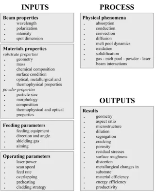
Quality and properties of laser cladding coatings can be determined by a large variety of factors such as clad geometry, microstructure, dilution, presence of defects, residual stresses, distortion, surface roughness, metallurgical changes in substrate and process efficiency. These factors, more or less important, are influenced by laser cladding process parameters and, consequently, by physical phenomena occurring in the cladding process. The chart in Figure 1.16 summarizes parameters and phenomena involved in the process, grouping them as inputs, process and outputs.
Process parameters can be classified in beam, feeding, materials and operating parameters. Beam and feeding parameters are generally fixed and are dictated by the choice of equipment, laser and optics. Materials parameters are related to the choice of additive material and substrate, and include the powder particles properties (particle size and morphology, chemical composition, thermophysical and optical properties) and the substrate properties (geometry and mass, chemical composition, surface condition, thermophysical and optical properties). Operating parameters can be changed by the laser cladding operator and their variation affects the process results. Among these, laser power (P), scanning speed (V) and feeding rate (F) are considered the principal parameters since they have the largest effect on the characteristics of the coating. Following, interactions present in literature of these three principal parameters with clads basic features are reported.
Figure 1.16. Inputs, outputs and process parameters of laser cladding by powder injection.
Aspect ratio, which is defined as the ratio between width and height of the clad (W/H), is affected consequently: as clad height, aspect ratio strongly depends on feeding rate and scan speed [100,101]. Substrate melting is principally controlled by the energy available per unit mass of powder P/F: dilution increases on increasing the laser power [97,98,102] and decreases on increasing the feed rate [88,93,94,100]. An increase in the scan speed, especially in thin beads, tends to increase dilution [100,103-105], while for clad with higher bead heights this influence becomes less significative [8]. The comprehension of the correlations between processing parameters and clad characteristics is fundamental for the production of defect-free coatings with desired geometry, fusion bond and low dilution. Basically, once the additive and substrate materials are selected, a good laser cladding process can be guaranteed by the adequate proportion between material fed and laser energy supplied. This concept can be seen in the work of Steen et al. [106], who showed the feasibility window of a laser cladding process with a Stellite 12 powder using a 2 kW continuous-wave C02 laser in a diagram
Chapter 1 – Laser cladding
19 needed to melt the powder, can be correlated with P/FD: this parameter can give the maximum value before dilution sets in. Finally, the combined parameter PVD/F2 is correlated with the aspect ratio: since aspect ratio must be higher than 5 to avoid inter-run porosity (or, alternatively, contact angle must be higher than 100°), the value of this parameter for which aspect ratio is 5 sets another limit on the operating region.
As shown by the work of Steen, combined parameters are always used due to mutual interactions between processing parameters and due to the complexity of the laser cladding process. One of the most appropriate way to reveal operating window and investigate correlations is thus to create a process map. An example of such map is given by the work of de Oliveira et.al. (Figure 1.17) [91].
Figure 1.17. Processing window for coaxial laser cladding where laser power (P) is reported as a function of the ratio between scan speed (V) and feeding rate (F). Vertical solid line determines the clad angle condition required for continuous coating; two solid hyperbolas terminate an area of allowed dilution and the grey area
shows the optimal clad layer window [91].
1.5 Clad characteristics
As stated above, properties of laser cladding coatings can be determined by a large variety of factors. In this section, the main characteristics of a clad are reported and discussed.
1.5.1 Clad geometry
The typical cross-section of a single clad bead is reported in Figure 1.18, where the most common parameters associated with clad geometry are shown. These are:
clad height (H): thickness of the clad bead above the original surface of the clad substrate;
clad width (W): width of the single clad bead;
clad depth (B): thickness of the substrate melted during cladding and added to the clad;
clad cross-sectional area (A): area of the clad cross-section;
HAZ depth (BHAZ): depth of the heat effected zone in the substrate;
HAZ area (AHAZ): area of the heat effected zone in the substrate;
contact angle (αwet): also known as wetting angle, is the angle between the substrate surface
and the tangent to the clad surface.
Figure 1.18. Typical clad cross-section with most common geometrical characteristics.
1.5.2 Dilution
Chapter 1 – Laser cladding
21 given by the ratio AD/(AN+AD) between the cross-sectional area of the molten substrate material (AD)
and the total cross sectional area of the clad (AN+AD) (Figure 1.19) [103,107-109].
Figure 1.19. Schematic drawing of the clad cross-sectional area showing the part of the cross-sectional area emerging from the original surface of the plate (AN) and the melted cross-sectional area of the substrate (AD).
Toyserkani et al. and Zhao et al. [11,110] used the ratio VD/V between the volume of molten substrate
(VD) and the total volume of the deposited layer (V). Toyserkani et al. and Huang et al. [11,108] also
correlated dilution with the ratio B/(H + B) between the molten substrate depth (B) and the sum of the molten substrate depth and the height of the clad bead (B + H) (Figure 1.18). All these methods are based on the dimensional and geometrical features of the clads. As an alternative, Salehi [111] used the iron content to determine dilution (D) through the equation D = (LFe – PFe)/(SFe – PFe), where PFe,
LFe and SFe are the iron concentration in the supplied powder, in the clad and in the substrate
respectively.
1.5.3 Microstructure
Functional properties and quality of coatings produced with laser cladding technology are strongly dependent on final microstructure.
The first prerequisite for a successful laser cladding process is to homogenize the melt pool, and homogenization of laser melt pool is guaranteed by convection. In fact, the large thermal gradients within the melt pool generate intense convection by Marangoni effect [112,113]. The parameter that characterize the influence of convection on liquid homogenization is the surface tension number S, defined by equation
𝑆 =( 𝑑𝛾
𝑑𝑇)∙𝑄∙𝐷
𝜇∙𝑉∙𝑘 (1.1)
Together with melt pool homogenization, the control of the solidification process is fundamental to obtain the desired microstructure. In laser cladding process cooling rates are very high, usually in the range of 5∙103
– 106 K/s, and solid state diffusive transformations are usually suppressed [8]. For this reason, in addition to the chemical composition and thermophysical properties of the coating alloy, final microstructure is mostly determined by the solidification process. In laser cladding solidification is frequently rapid since growth rates of the solid-liquid interface are often higher than 10 mm/s, and the typical microstructures detected in laser coatings are planar, cellular and dendritic [8,9]. For a given alloy, the solidification microstructure depends on the local solidification conditions, which are determined by the cooling rate (R) and the thermal gradient at the solid-liquid interface (G). Specifically, growth morphology of rapidly solidified layers is controlled by the parameter G/R. If G/R is higher than a critical value (G/R)* a planar solidification front takes place, while if G/R gets lower than this critical value the planar solid-liquid interface is destabilized and cellular or dendritic solidification occurs [60]. These solidification conditions (G and R) are function of the size and the geometry of the melt pool, which is in turn influenced by the laser cladding processing conditions such as laser power, scan speed, feeding rate, beam diameter or temperature of the substrate [114]. In particular, as it can be seen in Figure 1.20, they can be expressed as function of the depth of the formed bead.
Figure 1.20. Transverse cross-section parallel to cladding direction cut through the centreline of the clad bead showing the solidification rate (R), the scan speed (V), the angle (θ) between them and the growth rate of
dendrites (Vd) [8].
The correlation between the solidification rate (R) and the scan speed (V) is
𝑅 = 𝑉 ∙ cos 𝜃 (1.2)
Chapter 1 – Laser cladding
23
Figure 1.21. Schematic illustration of the formation of the cladding layer and crystallographic analysis [118].
Epitaxial solidification begin on the substrate without the need for nucleation and proceed unidirectionally towards the top. At the beginning of the solidification, at the bottom of the melt pool, a plane front solidification zone appears since the liquid metal maintains contact with the solid substrate (solidification rate is 0 and G/R presents and infinite value). With the propelling of the solid-liquid interface and the accumulation of heat, R increases rapidly and G decreases leading to a lower value of G/R: the planar front evolves to a cellular, and eventually to a dendritic, interface as G/R decreases. Because of the rapid variation of G/R, this interface is very narrow. Progressively the value of G/R decreases until it reaches a value that remains constant during most of the solidification process: in this region, which follows the cellular interface zone, dendritic solidification appears. Cellular and dendritic solidifications are usually columnar in shape and tend to grow perpendicular to the coating-substrate interface (or perpendicular to temperature isotherms) since heat is mostly dissipated through the substrate and, along this direction, the steepest thermal gradient is developed. Close to the surface of the clad layer, finally, the heat is mostly dissipated through the surrounding atmosphere and G is not predominant anymore: for this reason, in this region dendrites become very fine and disorientated [118].
1.5.4 Coating defects
The main defects that can be present in coatings produced with laser cladding are cracks and pores/voids.
may form. Low dilution and high solidification rates limit the problem of the hot cracking because less solute redistribution occurs, leading to a more uniform composition of the solidification structure [119,120].
Brittle cracks are generated during cooling, when the hot coating tries to undergo shrinkage but it is constrained by the relatively cold and rigid substrate. If the ultimate tensile strength of the alloy is exceeded by the resulting tensile stress and all the possible deformability of the working piece is utilized, brittle cracks occur. These cracks are generally perpendicular to the clad/substrate interface. To avoid the formation of such cracks, substrate preheating is an efficient solution [8].
The presence of pores or voids in the clad layer may be caused by several reasons, and it can be classified according to its position in the clad layer. Porosity inside the clad can be the result of the formation of gas bubbles entrapped into the solidifying melt pool. Internal porosity can also be present if solidification proceeds in different directions: in this case, some region of the melt can be enclosed. Upon solidification, when contraction of these enclosed region occurs, tensile stresses in the layer are generated and holes may be found. Porosity at the clad-substrate interface can be caused by minor flaws on the substrate surface (such us grease, oxides, defects and so on) that may influence the surface tension and consequently the bond between the coating material and the substrate. Finally, inter-run porosity may occur between adjacent beads in multiple-beads laser cladding. These kind of pores are usually caused by an incorrect design of the laser cladding process (too low aspect ratio) [12].
Excessive dilution and compositional non-homogeneities can also be considered as defects in laser cladding.
1.5.5 Residual stresses
In laser cladding, the laser beam is a very localized heat source having high intensity and short interaction times. For this reason, large thermal gradients spring between the hot molten clad layer and the relatively cold solid substrate or, in case of multiple-beads laser cladding, the adjacent bead. During the initial rapid cooling the clad material tends to shrink, but the contraction is restricted by the substrate and the adjacent bead: this leads to the formation of tensile stresses [67]. These tensile stresses are directly related to the thermal expansion coefficient of the clad material (αC), its Young’s
modulus (EC) and the temperature difference between the melting temperature of the clad material and
the temperature of the substrate during the process (ΔT) according to the equation
𝜎𝑡ℎ= 𝐸𝐶∙ 𝛼𝐶∙ ∆𝑇 (1.3)
Chapter 1 – Laser cladding
25 volume changes due to phase transformation are assumed, resultant stresses can be estimated through equation
𝜎 =(𝛼𝐶−𝛼𝑆)∙(∆𝑇𝐼)∙𝐸𝐶
1−𝜈𝐶 (1.4)
where σ is the resulting residual stress, αC and αS are the thermal expansion coefficients of the clad and
of the substrate material respectively, ΔTI is the temperature difference between melt pool and
substrate, EC is the Young’s modulus of the coating material and νC is the Poisson’s number of the
coating material [121].
The difference between the thermal expansion coefficient of coating and substrate play a fundamental role in the generation of residual stresses. If αC is higher than αS, the larger is the difference between
the coefficients, the higher are the tensile stresses in the coating layer; if αC is lower than αS, the larger
is the difference between the coefficients, the lower are the tensile stresses [8].
The effect of the temperature is clear: the lower is the difference between the melt pool and the substrate, the lower are the resultant stresses. Substrate preheating, which lowers the temperature difference, has always a positive effect on decreasing the tensile stresses in the coating in any condition. Moreover, substrate preheating favours the relaxation of the evolving stresses because decreases cooling rates, which allows more time for plastic deformation and creep to occur [8].
Inhibit the formation of tensile stresses in the coating layer is always positive: tensile stresses have detrimental effect on fatigue, tensile, wear and corrosion behaviour of the coating and may jeopardize the integrity of the coating [8].
1.6 Energetic efficiency and productivity of laser cladding process
In laser cladding, the energy necessary for the process is supplied by the laser light. The interaction between the laser electromagnetic radiation and both the powder particles and the melt pool, which involves the absorption/reflection phenomena of laser light, are decisive to determine energetic and melting efficiencies: these affect not only the quality of the final coating, but also process productivity and thus costs. Therefore, the comprehension of the energy partitioning in the laser cladding process is of great interest [8]. In Figure 1.22, a schematic illustration of the energetic redistribution for a blown powder cladding process during its steady-state is reported.
Before reaching the workpiece, the laser beam passes through the powder particles jet and the laser light interacts with the powders: part of the energy that hits the powder is reflected off the particles surface (EP,refl), while the rest of it is absorbed by them. As a consequence the laser beam results to be
attenuated by the powder jet, and the effective laser power available at the melt pool surface is lower. When the “attenuated” laser light hits the melt pool, a fraction is reflected off the melt pool surface while the remaining part is absorbed by the cladding system. The energy absorbed by the workpiece is divided as follow: part of it is used to heat up, melt and superheat the powder and the substrate (i.e. the energy to produce the coating EC, which is equal to the sum of EP and ES), another part is lost by
conduction from the melt pool into the substrate (i.e. energy to form the heat affected zone EHAZ and to
heat up the base material Ebulk) and the remaining small part is lost by radiation and convection from
Figure 1.22. Schematic illustration of the energetic redistribution for a blown powder cladding process during its steady-state [122].
Reflection and absorption of laser irradiation by the melt pool surface play a key-role in the energy balance. Laser absorption by metallic surfaces strongly depends on the laser light (polarization and wavelength), the optical properties of the coating material and the angle of incidence (i.e. the angle between the laser beam and the normal to the melt pool surface, which is assumed to be flat). Absorptivity, defined as the ratio between the absorbed part of the incoming radiation and the total incoming radiation, is correlated to these factors through Fresnel’s equations
𝐴𝑝= 4∙𝑛∙cos 𝜃𝑖𝑛
(𝑛∙cos 𝜃𝑖𝑛+1)2+(𝑘∙cos 𝜃𝑖𝑛)2 (1.5)
𝐴𝑠= 4∙𝑛∙cos 𝜃𝑖𝑛
(𝑛+cos 𝜃𝑖𝑛)2+𝑘2 (1.6)
where θin is the angle of incidence, n is the refraction index and k is the extinction coefficient. The
refraction index and the extinction coefficient are optical constants of the coating material and are influenced by temperature and laser wavelength [50,55,125]. In specific, they depend on plasma, laser and collision frequency [126]. In equations (1.5) and (1.6) the suffixes p and s denote the polarization condition of the laser beam: p-polarized light is a linearly polarized radiation having the electric field vector parallel to the plane of incidence, while s-polarized light is a linearly polarized radiation having the electric field vector perpendicular to the plane of incidence. In the case of circular polarization or with randomly polarized beams, the average absorptivity can be estimated as the average values of the p- and s-absorptivity
𝐴𝑎𝑣 =1
Chapter 1 – Laser cladding
27 Fresnel’s equations are valid for opaque medium when (n2
+k2)>>1, as it is for metals at wavelength higher than 500 nm [125]. Since in these conditions transmissivity is equal to 0 [50], reflectivity can be calculated as well
𝑅𝑝= 1 − 𝐴𝑝=(𝑛∙cos 𝜃𝑖𝑛−1)
2+(𝑘∙cos 𝜃𝑖𝑛)2
(𝑛∙cos 𝜃𝑖𝑛+1)2+(𝑘∙cos 𝜃𝑖𝑛)2 (1.8)
𝑅𝑠= 1 − 𝐴𝑠=(𝑛−cos 𝜃𝑖𝑛)
2+𝑘2
(𝑛+cos 𝜃𝑖𝑛)2+𝑘2 (1.9)
𝑅𝑎𝑣= 1 − 𝐴𝑎𝑣=12∙ (𝑅𝑝+ 𝑅𝑠) (1.10)
In Figure 1.23 an example of the typical absorptivity curves obtained with Fresnel’s equations are reported for iron at two different laser wavelengths (λ = 1.06 μm for the Nd:YAG laser and λ = 10.64 μm for the CO2 laser) [127].
Figure 1.23. Typical absorptivity curves obtained with Fresnel’s equations for iron at two different laser wavelengths: λ=1.06 μm for the Nd:YAG laser (left) and λ=10.64 μm for the CO2 laser (right).
From a practical point of view, in laser cladding the angle of incidence can be modified by varying the processing parameters: for instance, when powder feed increases the thickness of the coating increases consequently, leading to a more inclined melt pool (i.e. higher angle of incidence). As a consequence, when a linearly p-polarized laser beam is used, absorption increases because the incident angle approaches the well-known Brewster angle [88,99,124]. The angle of incidence can also be modified by simply varying the inclination of the laser beam with the same effect on absorption. Examples of this are reported in literature, were laser remelting tests at different angles of incidence were conducted [128,129]. With randomly polarized laser beams, anyway, such a positive Brewster effect cannot be realized and absorptivity cannot be modified significantly [8].
Figure 1.24. Modelled distributions of the input laser power for HPDL, Nd:YAG and CO2 laser types [130].
Energetic efficiency of the process, in this work estimated approximately around 15 – 50 % according to the laser source, is however lower than conventional welding processes such us PTA (50 – 70%), TIG (60 – 80%), MIG (70 – 80%), SAW and EBW (80 – 90%) [131].
Energetic efficiency have a direct effect on process productivity (i.e. deposition rate), since productivity is mainly related to the effective laser power available by the system. As shown by Figure 1.25, where deposition rates of laser cladding trials with different alloys (Fe-, Ni- and Co-based) on Fe-based substrates are reported as a function of laser power, on increasing the laser power productivity tends to increase. Moreover, short-wavelength lasers and hybrid processes favour higher deposition rates [8].
29
Chapter 2
Experimental procedures
2.1 Powders
The powders used for the present thesis work have been produced by Höganäs AB. Powders have been realized with the water-atomization process and have spherical morphology. The nominal chemical compositions of the powders utilized, provided by Höganäs AB, are summarized in Tables 2.1 - 2.3 together with their particle size.
Table 2.1. Nominal chemical compositions of Ni-based powder used.
Ni-based powder particle size C Si Bo Fe Ni Cr Mo Nb
[μm] [%] [%] [%] [%] [%] [%] [%] [%]
NiBSi 53 – 150 ≤ 0.06 3.0 2.9 0.2 bal. - - -
Inconel 625 53 – 150 ≤ 0.03 0.40 - 1.4 bal. 21.5 9.0 3.8
Table 2.2. Nominal chemical compositions of Fe-based powder used.
Fe-based powder particle size C Si Fe Cr Ni Mo Mn
[μm] [%] [%] [%] [%] [%] [%] [%]
316L 53 – 150 ≤ 0.03 0.8 bal. 17.0 12.0 2.5 1.5
Table 2.3. Nominal chemical compositions of Co-based powder used.
Co-based powder particle size C Si Fe Cr Ni Co Mo W
[μm] [%] [%] [%] [%] [%] [%] [%] [%]
Stellite 1 53 – 150 0.25 1.0 1.5 27.0 2.8 bal. 5.5 - Stellite 12 53 – 150 1.4 1.1 1.0 28.5 1.5 bal. - 8.0
Stellite 21 53 – 150 2.4 1.1 - 30.0 - bal. - 12.5
In order to study the dissolution behaviour of the tungsten carbides in a Co-based matrix, Stellite 12 and Stellite 21 powder were mechanically mixed with a mixture (65/35 vol.% respectively) of spherical and angular cast tungsten carbides having particle size ranging from 45 to 100 μm and a phase content of 61% W2C and 39% of WC. MMC powder combinations, ratios and hard particulate
Table 2.4. Details of the MMC powder combinations used.
powder wt. vol. carbide type shape phases density carbide size
[%] [%] [%] [%] [g/cm3] [μm]
Stellite12/WC 50/50 ≈65/35 fused/crushed spherical and angular
W2C and WC
(61/39 vol.%) 16.6 45 – 100 Stellite21/WC 50/50 ≈65/35 fused/crushed spherical
and angular
W2C and WC
(61/39 vol.%) 16.6 45 – 100
2.2 Substrates
The substrates used for the present thesis work are grounded plates of mild steel and grey cast iron having dimensions of 100 x 35 x 10 mm. The nominal chemical compositions of the substrates utilized are summarized in Table 2.5.
Table 2.5. Nominal chemical compositions of the substrates utilized.
substrate C Si Cr Mn Ni P S Mo Fe
[%] [%] [%] [%] [%] [%] [%] [%] [%]
grey cast iron 2.9 – 3.6 1.8 – 2.9 - 0.4 – 0.7 - max 0.3
max
0.1 - bal. mild steel 0.37 – 0.44 max 0.4 max
0.4 0.5 – 0.8 max 0.4 max 0.045 max 0.045 max 0.1 bal.
2.3 Laser cladding equipment
Laser cladding experiments have been carried out using a 4 kW Coherent Highlight 4000L direct high power diode laser (HPDL), mounted on an ABB IRB 2600 six-axis robot system. Laser operating wavelength was 808 nm. Laser beam, having a rectangular shape, was focused to a spot size of 12 x 1 mm2: 1 mm along the fast axis, i.e. scanning direction, and 12 mm along the slow axis. Intensity distribution had the classical “top-hat” profile along the slow axis.
Powder feeding have been achieved using a Thermach AT-1200 rotary powder feeder and a Coax11 coaxial type powder feeding nozzle (Fraunhofer IWS), tailored for rectangular or scanned line laser spots. Powder was fed into the melt pool, perpendicularly to the surface of the base material, from the opening of four channels on one side of the head only. The angle between the laser beam axis and the normal to the substrate surface (αL) was fixed at 28 degrees (Figure 2.1).
Chapter 2 – Experimental procedures
31
Figure 2.1. Schematic of the laser cladding equipment used.
2.4 Processing parameters
In the present work many batches have been produced by varying the three main processing parameters, i.e. the laser power P, the scan speed S and the feeding rate F. Different combinations of powders and substrates have been utilized. In some cases, substrate preheating up to 400°C has been performed in a furnace or with oxy-fuel torch. Processing conditions ranges for the different batches produced are reported in Table 2.6.
Table 2.6. Processing conditions for the different batches produced.
powder substrate preheating P F V
[kW] [g/s] [mm/s]
Stellite 1 mild steel - 2.0 – 3.8 0.3 – 0.9 1 – 8
NiBSi mild steel - 2.0 – 3.8 0.3 – 0.9 1 – 8
316L mild steel - 2.0 – 3.8 0.3 – 0.9 1 – 8
In625 mild steel - 2.0 – 3.8 0.3 – 0.9 1 – 8
NiBSi mild steel 400°C, furnace 2.0 – 3.8 0.3 – 0.9 1 – 8 NiBSi grey cast iron 400°C, furnace 2.0 – 3.8 0.3 – 0.9 1 – 8
WC+Stellite 12 mild steel - 2.0 – 4.0 0.5 5
WC+Stellite 21 mild steel - 2.0 – 4.0 0.5 5
WC+Stellite 12 mild steel 400°C, oxy-fuel torch 2.0 – 4.0 0.5 5 WC+Stellite 21 mild steel 400°C, oxy-fuel torch 2.0 – 4.0 0.5 5
Figure 2.2. Typical sample produced showing the selected cladding strategy
2.5 Coatings characterization
2.5.1 Microhardness and hardness
The microhardness tests have been performed under a Paar MHT-4 Vickers micro-indenter. A 0.1 kg load has been applied for a time of 10 s. A minimum of 8 indentations have been executed for every tested sample. The samples have been cut in order to reveal the clad cross-section and have been prepared through the classical metallographic procedure (i.e., polishing with papers and cloths and eventually etching).
The hardness tests have been carried out under an EmcoTest M4U 025 Rockwell indenter. A pre-load of 10 kg is applied for 2.5 s; then, a load of 150 kg is applied for 2.5 s (HRC). A minimum of 8 indentations have been executed for every tested sample. The samples have been prepared by surface polishing of the top of the clad.
Mean values and standard deviations have been calculated for every data batch.
2.5.2 Light Optical Microscopy (LOM)
A Zeiss Light Optical Microscope has been used for the optical characterization of the material microstructures. Digital images have been acquired by a Leica DC300 system connected to the microscope’s optical system. The samples have been prepared through lapping and polishing with abrasive papers (220, 500, 800, 1200 and 4000 respectively) and diamond cloths (6, 3 and 1 μm respectively).
Chapter 2 – Experimental procedures
33
2.5.3 Image Analysis
The image analysis software ImageJ has been used to measure the main geometrical features of the clad-cross section as schematically represented by Figure 1.18 in Chapter 1.5.1. In case of the coatings with tungsten carbides, image analysis has been utilized to investigate dissolution (see Appendix 1).
2.5.4 Scanning Electron Microscopy (SEM) and Energy-Dispersive X-ray
Spectroscopy (EDXS)
A Philips XL30 Scanning Electron Microscope (SEM), operating in high vacuum atmosphere, has been used for the observation of the solidification microstructures and microstructural details (e.g., carbides in WC + Co-based alloy coatings, oxidation scale in In625 coatings, and so on).
The scanning electron microscope was equipped with an Energy-Dispersive X-ray Spectroscopy (EDXS) device, which has been used for the microstructure and microstructural details investigation and for the study of dilution (see Appendix 2).
2.5.5 X-Ray Diffraction (XRD)
X-Ray Diffraction (XRD) analysis was done using a Cu-k α source (λ = 1.5418 Å), and an Image Plate (IP) over the 2θ-range from 30° to 120°, in reflection geometry. The experimental patterns were elaborated with the Rietveld method using the MAUD (Materials Analysis Using Diffraction) software.
2.5.6 Calorimetric experiment
The calorimetric tests have been performed in-situ during laser cladding experiments, by measuring the temperature of the sample during cooling (see Appendix 3). For the temperature measurement, two S-type thermocouples have been used. Thermocouples have been connected to an Intab AAC-2 data logger for the data acquisition. Data analysis has been realized by the LabVIEW 7.0 software.
2.5.7 Thermogravimetric Analysis (TGA)
Thermogravimetric Analysis (TGA) has been performed to study the thermal oxidation behaviour of the In625 coatings. For this purpose, isothermal treatments for 3 hours at different temperatures (1100, 1150 and 1200°C) have been made and a constant air flux (100 ml/min) has been insufflated during the test. A heating rate of 40 °C/min and a cooling rate of 50 °C/min have been applied in order to reach the desired temperature and, subsequently, to cool down the sample. A subtraction curve has been acquired on the empty crucible for each measurement.
2.6 Powders characterization
2.6.1 Density
The density of the different powders used has been determined using an AccuPyc II 1340 Gas Pycnometer. The instrument has been installed and calibrated to measure density according to the ASTM B923-10 standard.
2.6.2 Normal spectral absorbance
Normal spectral absorbance has been measured with an Ocean Optics USB4000 optical spectrometer, which disperses and records the full reflected spectrum within an integration time of 10 second. Radiation has been created by a DH2000-S Deuterium Tungsten Halogen Light Sources. Three indentations have been executed for every tested powder (see Appendix 4).
2.6.3 Differential Scanning Calorimetry (DSC)
The Differential Scanning Calorimetry (DSC) have been carried out in a Netzsch 409-PC apparatus. Alumina crucibles have been employed.
35
Chapter 3
Results and discussion
As seen in Chapter 1.4, the three principal processing parameters in the laser cladding process are the laser power, the scan speed and the feeding rate. The reason is their large effect on the final characteristics of the coating such us geometry, dilution, microstructure, presence of defects, particles dissolution, process efficiency and so on. In the following chapters, the effects of the principal processing parameters on geometrical features, dilution, energetic and material efficiency are investigated for different cladding materials. In particular, physical/analytical models to estimate the final geometrical characteristics and to evaluate the
![Figure 1.2. Thickness ranges of various surface engineering treatments [2].](https://thumb-us.123doks.com/thumbv2/123dok_us/539500.2053479/10.595.79.521.61.311/figure-thickness-ranges-various-surface-engineering-treatments.webp)
![Figure 1.4. Process map for various laser applications in materials processing [50].](https://thumb-us.123doks.com/thumbv2/123dok_us/539500.2053479/14.595.188.404.412.634/figure-process-map-various-laser-applications-materials-processing.webp)
![Figure 1.6. Schematic of different laser material processing techniques [11].](https://thumb-us.123doks.com/thumbv2/123dok_us/539500.2053479/16.595.142.457.549.754/figure-schematic-different-laser-material-processing-techniques.webp)
![Figure 1.10. Movement of molten front with time at various laser powers [60].](https://thumb-us.123doks.com/thumbv2/123dok_us/539500.2053479/19.595.119.479.73.295/figure-movement-molten-time-various-laser-powers.webp)
![Figure 1.11. Typical blown powder laser cladding equipment with (a) coaxial nozzle and (b) lateral nozzle [11]](https://thumb-us.123doks.com/thumbv2/123dok_us/539500.2053479/20.595.82.516.86.341/figure-typical-powder-cladding-equipment-coaxial-nozzle-lateral.webp)