Design of an AC Servo Controller for a Dynamic
Simulation Test System for Hydraulic Excavators Based
on a System-on-chip Architecture
https://doi.org/10.3991/ijoe.v14i07.8975Yu Bo
Jilin Institute of Chemical Technology, Jilin City, China
Xu Chunbo
Jilin University, Changchun, China
Qiaoruibo
China University of Mining and Technology, Beijing, China
Abstract—The AC servo system of hydraulic excavator dynamic simulation test system is studied in this paper.The AC servo controller based on C8051F410 on-chip system is designed in this paper. The dynamic characteris-tics of AC servo are tested and the fault treatment measures of AC servo con-troller are improved. Comparison between traditional PID and improved PID algorithm in AC Servo Controller by dynamic Simulation Test system, the im-proved PID algorithm suitable for dynamic simulation test system is obtained, and the response characteristics of the improved PID algorithm to AC servo system are tested. At the same time, the reliability of AC servo controller is tested.
Keywords—motion simulation platform; AC servo; on-chip system; PID
1
Introduction
In this paper, the dynamic simulation test system of hydraulic excavator is taken as the research object, and the AC servo controller is designed with the on-chip system as the core. The AC servo controller gives the comparison between ordinary PID, differential leading PID and incomplete differential PID. Combining with the respon-se characteristics of AC respon-servo, the control algorithm of differential antecedent plus incomplete differential PID is proposed.With the improved PID algorithm, the AC servo controller achieves the expected goal of the dynamic simulation test system of the hydraulic excavator.
2
Structure of dynamic simulation test system for hydraulic
excavator
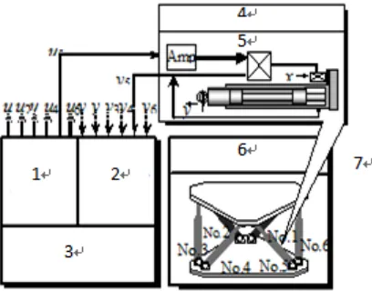
The hydraulic excavator dynamic simulation test system, as shown in Figure 1, in-cludes the cockpit, the dynamic upper and lower platform, the 6 degree of freedom electric cylinder, the AC servo motor and the AC servo controller. The 6 degree of freedom electric cylinder combined with the upper and lower platforms can achieve 6 basic movements, that is, the straight line moving along the direction XYZ axis and the rotation of the three axes around the axis of the XYZ axis. Through the 6 basic movements of the platform, the complex movement of the moving platform can be realized, and the free movement of the dynamic simulation test system of the hydrau-lic excavator is realized
Fig. 1 is a schematic diagram of the dynamic simulation test system for a hydraulic excavator, which is a closed loop system whose core is the AC servo controller. The 6 electric cylinders (including AC servo motor) of the 6 degree of freedom motion platform are controlled by 6 AC servo controllers. The AC servo controller can con-trol the telescopic motion of the electric cylinder according to the position commands issued by the PC machine, and drive the dynamic simulation test system of the hyd-raulic excavator to produce the corresponding action. An improved PID algorithm is used in the process of control, comparing the position signals of the input 6 electric cylinders with the position signals of 6 electric cylinders, and the rapid response to the telescopic length of each electric cylinder is realized after the PID operation.
3
Design of AC servo electronic control unit
1. Servomotor speed signal 2. Photoelectric coding and proximity switch conditioning 34. AC servo system 5.Servo motor drive 6.six degree of freedom motion platform 7.Electric cylinder
Fig. 1. Dynamic Simulation of Hydraulic Excavator
3.1 Hardware design of AC servo controller based on chip system
According to the interface design of AC servo controller, the AC servo controller is designed in the form of field bus (485 bus), and the MCU chip uses the C8051F410 model. C8051F410 is a fully integrated system type MCU on the hybrid signal. The CIP-51 kernel of the inner chip has a speed of 50MIPS, which can fully satisfy the signal acquisition of the dynamic simulation test system of hydraulic excavator and control for it.
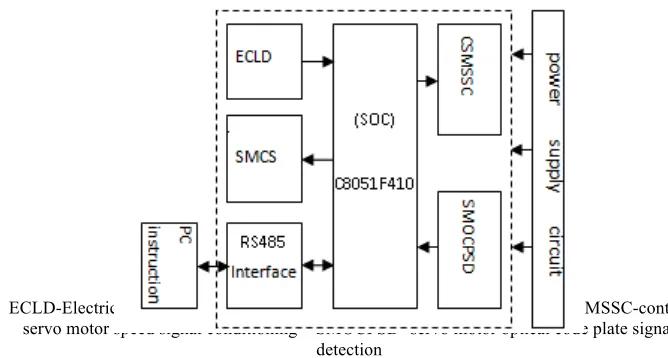
The principle block diagram of AC servo controller based on C8051F410 on chip system, as shown in Figure 2, includes C8051F410 on chip system circuit, electric cylinder low position detection circuit, servo motor control signal circuit, RS485 interface circuit, servo motor speed signal conditioning circuit, servo motor photo-electric code disk signal circuit and power circuit. The power supply circuit adopts a stable AC/DC module, which converts the 220AC power into multiple sets of DC power supply for the system, sensors and AC servo drivers. The RS485 interface circuit is used to communicate with the PC. The low level detection circuit of the electric cylinder is used to detect the initial position of the electric cylinder. The AC servo motor control signal circuit is used to control the starting / stopping command of the servo motor. In this paper, the signal detection circuit of servo motor photo-electric encoder is simply explained.
ECLD-Electric cylinder low detection – SMCS-servo motor control signal – CSMSSC-control servo motor speed signal conditioning – SMOCPSD- servo motor optical code plate signal
detection
Fig. 2. AC servo control system based on c8051F410
(1) When the internal clock of theC8051F410single chip is 24.5MIPS, and the C8051F410 timer / counter counts the photoelectric code disk, the maximum fre-quency of the C8051F410 timer / counter can reach 1/4 of the system clock (24.5MIPS) frequency. The minimum period calculation of SCM sampling is shown in equation (2), where the system clock is 1/T, and the minimum period of sampling is T2min.
(2) Thus, T1min> 10 * T2min can be obtained.
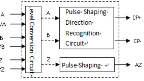
Therefore, C8051F410 microcontroller can use its timer / counter to count the pho-toelectric encoder signal. The structure block diagram of the phopho-toelectric code disk is shown in Figure 3.
structure shown in Figure 3, the AC servo motor is converted or reversed, and the number of positive rotating pulses and the number of reversing pulses can be counted, and the position of the electric cylinder can be known through the number of pulses.
Fig. 3. Photoelectric encoder circuit
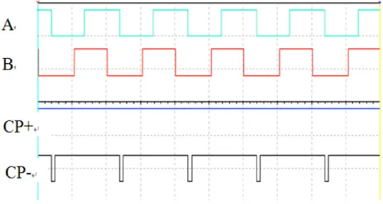
Fig. 4.Phase A ahead of phase B 90degree CP+ and CP- output waveform
For the photoelectric code disk structure shown in Figure 3, when the input A pha-se pulpha-se is ahead of the B phapha-se pulpha-se 90 degrees, its CP+ and CP- output waveforms, as shown in Figure 5, have pulse output to the forward CP+, and the reverse CP- out-put high level. The CP+ and CP- waveforms are respectively counted on the C8051F410 microcontroller timer / counter to count the motor's positive turn, and record the number of the positive turn of the motor. Through the above judgment, the length of the electric cylinder extended is known.
Fig. 5. Phase B ahead of phase A 90degree CP+ and CP- output waveform
3.2 Design of digital PID algorithm
The traditional positional PID transfer function is shown in equation (3).
(3)
The traditional position PID transfer function is discretized to equation (4).
(4) The Kp is the ratio coefficient, the Ti is the integral time constant, the Td is the dif-ferential time constant, the e(k) is the deviation value of the k sub sampling time, and the e(k-1) is the deviation value at the k-1 sub sampling time, u(k) is the output value of the single chip microcomputer at the time of the k sub sampling.
The formula (4) can see that the values of u(k)are all related to the state of the past.
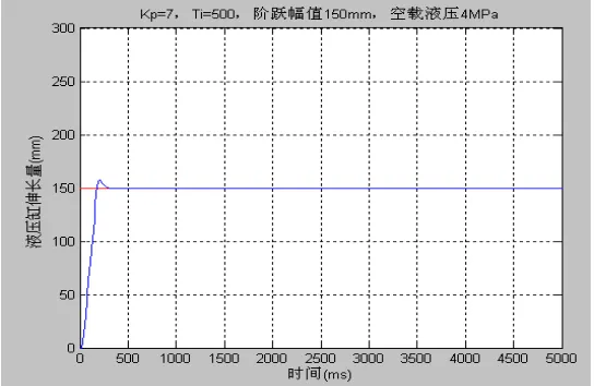
Fig. 6.Traditional PID step corresponding curve
In the traditional position PID, due to the introduction of the differentiation ele-ment, it is particularly sensitive to interference, and the output of the differential term only plays an exciting role in the first period. For a system with larger time constant, its adjustment function is small and cannot achieve the goal of precontrol error. Ge-nerally, the amplitude ofKpTd/T is generally large, and it is easy to cause data
over-flow. Too fast and excessive changes of differential links will also have adverse effects on executing agencies. In order to overcome these shortcomings, the differen-tial link in the PID algorithm is transformed into a low pass filter, and the given value is filtered, as shown in equation (5).
(5) TheUD(s)in theequation (5) is discretized to equation (6).
(6) Theequation (6) is finished (7.)
(7) If Tf/(Tf+T)=!, then T/(Tf+T)=1-!,Kd=KpTd/T,ud(k) can be reduced to form (8).
When the r(k)is given as a step signal,when r(k)=1,k=0,1,2,3,……Can be obtained.
(9)
(10)
(11)
(12)
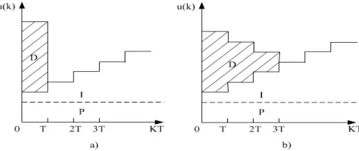
By the formula (9) ~ (12), when the incomplete differential is introduced, the pulse height of the differential output decreases in the first sampling period, and then(!<1).gradually attenuates according to the law of!ku
d(0).Therefore, incomplete differential can effectively overcome these shortcomings and has better control chara-cteristics. The comparison between traditional PID and incomplete differential PID is shown in Figure 7.
a) Traditional PID b) Incomplete differential PID
Fig. 7. Comparasion of Traditional PID with Incomplete differential PID
From Figure 7, it is known that when PID only differentiate the quantitativer(t), the change of the controlled quantity is usually relatively mild. This kind of differential control for the quantitative advance obviously improves the dynamic characteristics of the system.
According to the contrast of PID in Figure 5 and the application of AC servo in practice, the differential pre added incomplete differential position PID formula is adopted, and the improved algorithmis shown as (13).
In formula (13), the given value R(s) is used as a differential term. It is an impro-vement in considering that AC servo control is a servo system and the given value R(s) is a differential term, which can improve the dynamic characteristics of the sys-tem. In computer programming, the equation (13) is discretized into a differential equation (14).
(14)
In formula (14), e(k)is the result of the k deviation operation. is the result after k time deviation integral, ud(k) is the result of the K time adding the given
value to the inertial link. ud(k) and ud(k-1) can be recursively recurred by the formula
(7), andud(0) = 0.
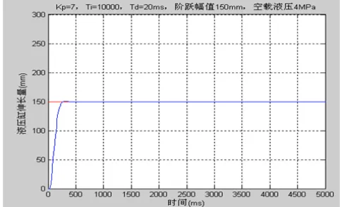
The step response of the actual electric cylinder output location is 150mm, using differential first and incomplete differential PID algorithm, as shown in Figure 7.
Through the above comparison, differential step ahead and incomplete differential PID algorithm step response curve can better improve the dynamic characteristics of the system, and the overshoot is also greatly reduced.
Fig. 8.Derivative ahead with incomplete different PID
4
Analysis of experimental results
1.Input signal 2.PID algorithm 3.Servo motor 4.Electric cylinder 5.photoelectric encoder 6.Cylinder displacement
Fig. 9. Block diagram of electric servo controller
1.1 Following characteristic test
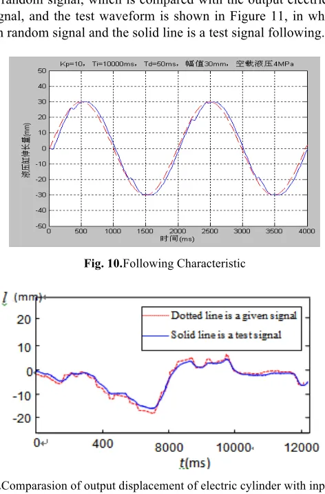
The input signal is given as a sine signal, and compared with the output electric cy-linder displacement signal, the test waveform is shown in Figure 10, in which the dotted line is a given signal and the solid line is the following signal. The input signal is given as a random signal, which is compared with the output electric cylinder dis-placement signal, and the test waveform is shown in Figure 11, in which the dotted line is a given random signal and the solid line is a test signal following.
Fig. 10.Following Characteristic
4.1 Contrastive test of AC servo controller based on chip system and conventional AC servo controller
In Figure 9, AC servo controllers are connected to the AC servo controller based on the on-chip system and the conventional AC servo controller respectively, and the step signal is added to the performance comparison test. The AC servo controller based on the on-chip system uses the differential pre - incomplete differential PID algorithm, and the conventional AC servo controller uses the traditional PID algo-rithm. The results of the test curves are shown in Figure 6 and figure 8 respectively. The transverse coordinates are time (unit: ms), the longitudinal coordinate is the ex-pansion length of the electric cylinder in the dynamic simulation test system of the hydraulic excavator (unit: mm), and Figure 6 is the displacement curve of the electric cylinder output under the traditional PID algorithm, and the 8 is the displacement curve of the output of the electric cylinder using the differential advance and incom-plete differential PID algorithm. From the result curve of the test, it can be seen that the two performance indexes of the AC servo system under the function of differenti-al advance and incomplete differentidifferenti-al PID differenti-algorithm are much better than those of the traditional PID algorithm.
5
Conclusion
1.In view of the dynamic characteristics of AC servo control system, an improved PID algorithm is proposed and applied in the project from a practical point of view. 2.The improved PID control algorithm has greatly improved the response
charac-teristics of AC servo system.
3.The application results show that the AC servo controller based on chip system is easy to operate and has strong anti-interference capability.
6
Reference
[1]XIAO YINGKUI, DINGXUAN ZHAO, WANG FANGRONG: Online Simulation of Re-mote Motion Based on 6-DOF ParallelPlatform. Journal of Agricultural Machinery, 2005 (6): 138-140.
[2]AN ZHUOJIN, SUN DELONG, XIA XIUFENG, translation:Signal Integrated Pro-ducts,Inc. [America]. Application Analysisof C8051FMicrocontroller. Beijing: Beijing University of Aeronautics and Astronautics Press,2002.
[3]AI XUEZHONG,ZHAO DING,TANG XING: Design of Electro-Hydraulic Servo Valve Controller for Engineering Robot Based on The System. Hydraulic and Pneuma-tic,2007(3):56-59.
[4]ZHAOJIANZHOU, ZHAO AI-LING. Design ofthe Control Circuit Based on the Position Detection of the Optical Code Disk Sensor. Electrical Automation,2006(2):75-79.
[6]ZHANG HONGYAN, ZHAO DINGXUAN, ZHENG WU:Improved Fuzzy PID Control Strategy for All-Hydraulic Drillers. Journal of Wuhan University of Technology (Trans-portation Science Engineering),2008(8):673-676.
[7]TAOYONGHUA. NewPID ControlApplication. Machine Industry Press,Beijing,(2000).
7
Authors
Yui Bo (1972- ), comes from Jilin, Jilin province. Master degree, associate profes-sor, the main research direction for computer control. (e-mail: [email protected], affiliation: College of Information & Control Engineer, Jilin Institute of Chemical Technology, Jilin City, 132022, China).
Xu Chunbo (1986- ), comes from Changchun, Jilin province. PhD, the main re-search direction for robot technology and mechanical system dynamics modeling.(e-mail:[email protected], affiliation: College of Mechanical Science and Engineering, Jilin University, Changchun, 130000, China).
Qiao Ruibo (1997- ),comes from Beijing, Beijing. Undergraduate student the main research direction forrobot technology (affiliation: School of Mechanical Electronic & Information Engineering, China University of Mining and Technology, Beijing, Beijing, 100000, China).