Development and evaluation of power consumption model for
no-till planter based on working parameters
Gao Dongming
1,
Li Lianhao
2*,
Qiao Xiaodong
3,
Khokan Kumer Sarker
4 (1. College of Material and Mechanical Engineering, Beijing Technology and Business University, Beijing 100048, China;2.College of Mechanical and Electrical Engineering, Henan Agricultural University, Zhengzhou 450002, China; 3. Beijing Research Center of Intelligent Equipment for Agriculture, Beijing 100097, China;
4. Bangladesh Agricultural Research Institute (BARI), Gazipur 1701, Bangladesh)
Abstract: In order to fully understand the relationships of power consumption of no-till planter among tractor, soil properties and working parameters which affect the field operation, the power consumption model for no-till planter applied to overcome the coupling difficulties was developed in the study. Based on operation depth of no-till planter and soil properties as constraints in accordance with a certain distribution, the relationship data among traction force, forward speed and power output shaft by field test were collected and analyzed. The results showed that the relationship between traction power and power-take-off (PTO) power was negatively correlated. Under the same power consumption condition, the relationship between traction force and the PTO torque was linearly correlated, and the slope was basically consistent. Different power consumptions corresponded to different intercepts. When the forward speed was 6-7 km/h and PTO shaft rotational speed was 370-450 r/min, lower power consumption with higher working efficiency can be achieved. There was a direct correlation between total power consumption and the square of rotational speed multiplied by forward speed. The maximum correlation coefficient was found around 0.82. The findings set up a foundation for designing control system of no-till planter.
Keywords: no-till planter, power consumption, models, working parameters, evaluation
DOI: 10.3965/j.ijabe.20171001.2310
Citation: Gao D M, Li L H, Qiao X D, Sarker K K. Development and evaluation of power consumption model for no-till planter based on working parameters. Int J Agric & Biol Eng, 2017; 10(1): 80–87.
1 Introduction
No-till planter is a key machine of conservation tillage. There is a great relationship among the power required in the work and its chop devices, opener, soil
Received date: 2015-12-27 Accepted date: 2017-01-02
Biographies:Gao Dongming, PhD, Lecturer, research interests: optimization of system design and numerical simulation, Email: [email protected]; Qiao Xiaodong, PhD, research interest: agricultural machinery, Email: [email protected];
Khokan Kumer Sarker, PhD, Research fellow, research interests: conservation agriculture, irrigation and water management, farm machinery, Email: [email protected].
*Corresponding author:Li Lianhao, PhD, Lecturer, Postdoctoral Fellow at Henan Agricultural University, research interests: intelligent agricultural machinery, water-saving theory and technology. Mailing address: College of Mechanical and Electronic Engineering, Henan Agricultural University, No.63, Nongye Road, Jinshui District, Zhengzhou 450002, China. Email: [email protected].
properties, straw mulching etc. In order to study the relationship among the above parameters, the relationship among the type of ditching parts, working depth and soil types were experimentally investigated[1,2]. The
relationship between the parameters of operating speed and traction resistance was studied and the relationship models of each parameter were developed[3,4]. Finite element (FE) models were established to simulate the soil cutting process and the force[5-7]. The torques of rotary cutting soils and the power consumption and fuel consumption model of farming machinery under different operating parameters were studied[8-11]. The vibration problem of rotary cutting parts during working was studied, which proved that the excitation of the machine or self-excitation vibration of the machine had a certain effect on the working quality and power consumption
[12-14]. Furthermore, the relationship between seeding
No-till planter was subject to the direct forces from tractor and soil in the field operation. There were some complex interaction relationships among operation parameters, tractor output parameters, soil surface conditions and operation quality etc. The function relations between some parameters caused by the coupling effect were known as implicit functions. This coupling relationship led to the fact that the study results obtained from the specific components were difficult to transplant applications. For the specific user of the machine, the purchased machine was often used for the seeding operation of a limited number of crops in the fixed plot. This indicated that the soil type of the machine operation was almost the same, and the depth of farming was the same as well.
For the above problems, the parameters such as operation depth and soil properties were taken as constants in accordance with some certain distribution characteristics, and the feedback interaction problem between no-till planter and the soil spatial heterogeneous characteristics and displacement delay feedback was analyzed. In this method, the interaction relationship among machines, different soil parameters and soil surface conditions were regarded as a black box to study its entirety input and output. We collected the data such as traction force, forward speed and PTO shaft parameters, etc. at the three-point hitch, and we studied the relationship between power consumption and traction, forward speed and PTO shaft parameters, which provided a basis for the design of parameter control system of no-tillage planter.
1 Interaction model of working parameters
1.1 Dynamics analysis
In the working process, the tractor achieved working feed through go-forward hanging node, and achieved operational requirements through PTO shaft driving working parts and all working parts of the machine operating in the soil. Analysis methods of the existing study can be summarized as the following aspects: Operational parameters or no-till planter parameters were analyzed and optimized by setting independent variables (such as the tractor working speed, PTO shaft rotational
speed, working depth, soil parameters and other factors) and the dependent variables (such as working efficiency, fuel consumption, working quality and other factors). The tractors, no-till planter and soil were studied as monomers in this method. However, due to soil parameters such as soil type, moisture, firmness and other factors are were the same, which affected on tractors and no-till planter differently. Therefore, it was difficult to find a theoretical method or testing relational models between working quality parameters and operating parameters. In addition, the interaction incentives between the no-till planter and the mulch on soil surface made no-till planter produce a certain frequency of vibration[18,19]. This vibration transmitted to the tractor through the three-point hitch of the tractor, and got a larger response, which will react on the seeding and inevitably affect the quality of work[19,20].
Under the ideal condition, working process of the no-till planter can be seen as a rigid body motion on the soil surface driven by tractor.
Since the cutting resistance led to a certain amount of elastically deformation in the soil cutting components, the stable working conditions were achieved by the balance between the elastic restoring force of the soil cutting components and the cutting resistance of the soil. The kinematic equations are shown as:
( ) ( ) ( ) ( )
mx t&& +cx t& +kx t =F t (1)
k=P0 /x (2)
where, x is the displacement on soil, m; m is the mass of cutting components, kg; c is the damping coefficient of cutting damper, N·s/m; k is the stiffness of the no-till planter, N/m; P0 is soil cutting resistance, N.
In reality, since soil parameters, surface flatness and floor coverings always distribute randomly, the dynamic process between machine and soil tends to appear the following two cases of excitation situation.
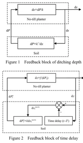
The first case is: when ditching components encounter the hard soil, the depth of the ditching feedback block to ditching components is shown in Figure 1.
displacement on soil is dx. According to Hooke’s law, the changes of soil cutting resistance produce additional rigidity of the ditching components k′ (N/m):
k′=dP/dx (3) And then, the real-time stiffness is expressed as:
k–k′=k–dP/dx (4) Thus, the kinematic equations are transformed into:
( ) ( ) ( d / d ) ( ) ( )
mx t&& +cx t& + k− P x x t =F t (5)
When ds decreases with dx increase, the ditching components become stable progressively. However, when ds increases with dx increase, dP increases with ds increase. So, stiffness expression is transformed into:
(k k− ′) 0<
(6)
This case leads stiffness of no-till planter to an equivalent negative stiffness[21,22], and ditching depth
gradually deviates from the set depth over time.
The second case is: feedback block of time delay between the rotary component and soil ( Figure 2).
Figure 1 Feedback block of ditching depth
Figure 2 Feedback block of time delay
The movement of the rotary blade is synthesized by the rotation of rotary shaft and the forward movement along the tractor direction. Under stable operation condition, this study assumes that s1 (m) is the cutting
depth of each blade, P1 (N) is the cutting resistance of
each knife. When the rotary blade contacts hard soil during the rotation, the blade is subject to instantaneous
cutting resistance increase dP1. The resistance
incremental affecting on no-till planter is bound to produce a vibration dz. After the blade rotating a certain time T (h), the next following blade will contact with the soil and lead to a cutting depth incremental s11. The
cutting depth incremental affecting on machines will generate a cutting resistance incremental dP11. So there
is the cycle and thus we get dP12, dP13….
Since the force at time
t
(h) is determined by the vibration at moment (t–T), the kinematic equations are expressed as:( ) ( ) ( ) ( )
mx t&& +cx t& +kx t =F t T−
(7) This motion process is either stable or diverging. The vibration of no-till planter will gradually increase in the case of dP1≤dP11≤dP12, otherwise the system tends to
be stable.
1.2 Modeling
The above analysis showed that the excitation and interaction of each parameter increases the difficulty of research. In response to this challenge, this study established a new model (shown in Figure 3) on the basis of studying tractor output, operational parameters and the working quality. In this model, the interaction relationship of machines, different soil parameters and soil surface conditions were regarded as a black box. And then, the dynamic parameters between the tractor and the black box were set as the research object. For the
modeling, a test system consisting of multi-stage
transmission, six-component force and torque acquisition system, speed sensor and other devices was used to
collect the component force in all directions Fuurt(N),
the torque of PTO shaft M′t (N·m), PTO shaft rotational speed ωt (r/min), and forward speed v (km/h) in the time
domain at three-point hitch location[23].
For no-till planter, the component force and the torque of PTO shaft subjected at three-point hitch were mainly decided by its mass, center of mass location, forward speed and soil reaction force. For these parameters, the mass and mass centroid position was known as constant values, and the force which machinery affected on soil was equal to the reaction force value of the soil. Therefore, the main tillage planter force on the soil was decided by the PTO shaft torque M′t, PTO shaft rotational speed ωt, the tractor forward speed v.
Force vector values Fuurt are expressed as a function
including the following parameters:
1( , , )
t t t
F =g M′ ω v
uur
(8)
In the component forces, the lateral forces and the force in direction of gravity did not work. Referring to the damping expression, the relationship between traction force in forward direction Fx and forward speed v are expressed as the following:
2 0 1 x
F =b +b v (9) where, b0 and b1 are the constant value to be determined.
Based on the power calculation formula, the real-time traction power (W1) is shown as:
3 1 x 0 1
W =F v b v b v= + (10)
For the no-till planter works in the same land and similar working content, factors which affected on the power consumption including soil parameters, tillage depth, mulch and other changes can be approximately regarded as a constant changing within a certain range.
For the rotary power, test showed that the power consumption was affected by the rotary speed ratio λ[24], which is expressed as:
t
R v
ω
λ= (11)
where, R is the rotor radius, m.
The Equation (11) showed that, when the factors including soil parameters, operating depth, mulch, etc. were constants, the rotary power consumption (W2) had
some relationship with PTO shaft rotational speed ωt and forward speed v. If the soil parameters were set to constants, and on the basis of the power prediction empirical formula in the literatures[24-26], the rotary tillage power should be:
2 2 2 ( 3 3 t )
W =b v b +bω
(12)
where, b2 and b3 are the constant value to be determined.
Simultaneous Equations (10) and (12), the total power consumption model of no-till planter (W) is expressed as:
3 2
0 2 3 1 2 3
( ) t
W = b +b b v b v+ +b b vω (13)
2 Materials and methods
2.1 Experiment conditions
The tillage experiments were carried out in Laishui County, Hebei Province. The size of test field was a flat land about 350 m×50 m, soil texture was sandy loam, and the altitude was 46 m. Working temperature was 18°C. Surface roughness before treating was soil without conducting after harvesting corns. The surface of soil was covered with numerous straws (the coverage amount was about 1.2 kg/m2). The moisture content of soil was about 15%-20%.
Test equipment was composed of tractors, field testing platform and 2BMSF-12/6 type no-till Planter. A 66 kW tractor (Calibration traction force 21.3 kN, PTO power 56.3 kW, PTO shaft rotational speed 540 r/min) was used to towing field testing platform and no-till Planter. The tractor type was LOVOL EUROPARD TD904 wheeled tractor. Calibration traction force was 21.3 kN, engine calibration power was 66.2 kW, calibration rotational speed was 2300 r/min, maximum torque/rotational speed was ≥315 N·m/1500-1700 r/min. Field test platform was equipped with a transmission, which can regulate the PTO shaft rotational speed range from 0 to 1000 r/min with a total of 16 stalls.
The basic parameters of 2BMSF-12/6 no-till planter were: static weight 780 kg, supporting power 44.1- 58.8 kW, sowing wheat with 12 rows, fertilizing wheat with 6 rows, work efficiency 0.6-0.73 hm2/h. The tillage depths for rotary cultivator were 10 cm, rotary width 2.2 m.
2.2 Test content and method
same distance. The minimum sampling frequency of the sensor was set to 0.1 m. Test area was composed of a stable area, measuring area and parking area. The size of measuring area was 400 m for the tests. The length of stabilizing zone was 5 m located in front of the measuring area. Parking area was located behind the test area, shown with the mark.
3 Test results and analysis
3.1 Test results
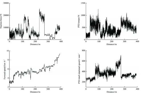
The test results including forward speed, no-till planter traction force in the forward direction, PTO shaft rotational speed and PTO torque were shown in Figure 4. The following conclusions can be obtained from Figure 4: (1) Under the premise of increasing forward speed slowly, traction force of no-till planter in the forward direction and the PTO torque did not change significantly. (2) When the forward speed was 3 km/h, PTO shaft rotational speed was 300 r/min, the traction force in the forward direction and PTO torque required for the operation reached the minimum. (3) It can be obtained by studying the traction force peaks in Figure 4 that under the premise of no significant change in
forward speed, PTO torque can be reduced by increasing the PTO shaft rotational speed, but it will result in a huge increasing in traction force.
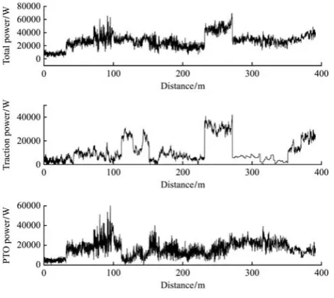
Traction power, PTO power and total power consumptions of no-till planter were shown in Figure 5. It can be seen from the comparison of three power dissipation that improving working efficiency (forward speed) did not lead to power increase absolutely. Interactions of traction force, PTO torque and PTO shaft rotational speed affected power dissipation greatly. Figure 5 showed that, when the forward speed was 2.5- 3 km/h and PTO shaft rotational speed was 200-300 r/min, the total power consumption reached the minimum, but due to the low forward speed, the working efficiency was lower. Comparing the traction power and PTO power in 100-250 m section and 300-400 m section, the relationship between traction power and PTO power was negative correlation. The data analysis of Figures 4 and 5 showed, under the premise of no significant change in PTO shaft rotational speed; the interaction effects between traction power and PTO power significantly were significant.
Figure 5 Power consumption of no-till planter 3.2 Power response to working parameters
Setting the forward speed and PTO shaft rotational speed as the tractor output parameters, the total power consumption response surface contours of no-till planter was shown in Figure 6. The blue area to the red area represented the total power from Min to Max. The rectangular box in Figure was the stable changing area of the power. In this area, the forward speed was linearly related to the output shaft speed in the same power zone Blue area in Figure 6 showed that, when the forward speed was 6-7 km/h and PTO shaft rotational speed was 370-450 r/min, we will get the lower power consumption with higher working efficiency.
Figure 6 Power response surface to tractor output
Setting the traction force and PTO torque as the no-till Planter feedback parameters to tractor, the total power consumption contours of no-till Planter was shown in Figure 7. Different colors contours in the figure showed, under the same power consumption condition,
the relationship of traction force and the PTO torque was not only linearly related, but also the slope was basically consistent. Different power consumption corresponded to different intercept.
Figure 7 Power response surface to no-till planter feedback
The total power consumption contours of the PTO shaft speed and torque were shown in Figure 8. It showed that under the conditions of no violent fluctuations between the traction force and forward speed, the total power consumption was mainly decided by the PTO shaft rotation speed and torque. The higher the PTO shaft rotation speed was, the higher the total power consumption was.
3.3 Prediction models of total power consumption
Regressions analysis was performed on the total power consumption using sample data in Figure 6. The regression coefficients were obtained based on Equation (13). In regression analysis model, the total power consumption was set as the response variable, and variables v, v3, ωt, vω2t were set as independent variables. According to the modeling of the least square method and sample data, a number of possible multiple linear regression model were established between independent variables and the dependent variable:
3 2
1 4 5( t ) 6 7 t 8
y =b v +b vω +b v b+ ω +b (14)
3 2
2 4 5( t ) 6 8
y =b v +b vω +b v b+ (15)
3 2
3 4 5( t ) 7 t 8
y =b v +b vω +bω +b (16)
3 2
4 4 5( t ) 8
y =b v +b vω +b
(17)
5 6 7 t 8
y =b v b+ ω +b
(18)
In order to evaluate the effects of above regression models, coefficient of determination R2 was set as the model fitting test indicator for comparison. Coefficient of determination, also known as the goodness of fit R-Square, referred to the regression level to the sample data, which reflected the degree of influence between independent variables and dependent variables. Adjustment R2 (Adj. R2) eliminated the influence of the variables number to the model, so it can be used as the test criteria to compare models. Table 1 presented a summary of Adj. R2 for each regression models.
Table 1 Adjustment R2 for each regression models
Evaluation Index y1 y2 y3 y4 y5
Adj. R2 0.718 0.719 0.683 0.675 0.669
Range of Adj. R2 values was from 0 to 1. When Adj. R2 was closing to 1, better regression model achieved better results. As can be seen from Table 1, y2 was the
best regression result. By comparing y2 with y1, Adj. R2
values were slightly different. However, y1 had one
more independent variable ωt than y2. This indicated
that ωt had linear relationship with another variable in the regression equation. Therefore, to avoid multicollinearity, the total power consumption model for the forward speed and PTO shaft rotational speed was described by the following regression equations:
3+ ( 2)
101.58 0.0146 t 15770.07 91734.71+
W = v vω − v (19)
The F value of the model was 1375 in F-test, so, this regression equation was highly significant at the level of α=0.01.
In order to reject variables those who had no significant effects to the regression model, the statistically significant of each independent variables were judged by using significance test (t-test). The t-test results were shown in Table 2, which showed that the estimated parameters were significant to the model, and the independent variable vω2t was highly significant.
Table 2 T-test of each variable
Value Standard error t-value Prob>|t| Intercept 91734.71 4667.38919 19.6544 0
vω2
t 0.0146 2.49993E-4 58.39161 0
v3 101.58 6.02812 16.85156 0
v –15 770.07 972.00425 –16.22429 0
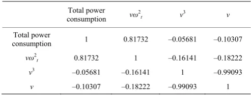
Because there were multiple variables in regression model, the variables may be associated with each other.
It was necessary to analyze each variable by using Pearson correlation analysis. The correlation analysis results were shown in Table 3.
Table 3 Correlation coefficients of indicators
Total power consumption vω
2
t v3 v
Total power
consumption 1 0.81732 –0.05681 –0.10307
vω2
t 0.81732 1 –0.16141 –0.18222
v3 –0.05681 –0.16141 1 –0.99093
v –0.10307 –0.18222 –0.99093 1
Table 3 showed that it was a positive correlation between the total power consumption and variable vω2
t, and reached a correlation coefficient maximum of 0.81732. This meant that there was a direct correlation between total power consumption and vω2t. There was a negative correlation between total power consumption and forward speed v and v3, which was considered less correlation. The independent variable vω2t had a low correlation with the other independent variables.
4 Conclusions
On the basis of this study, the following conclusions can be drawn.
1) In the conditions that the forward speed did not change significantly, increasing PTO shaft will reduce the PTO torque, but it will lead to the significant increase of the tractor power. In the conditions that the PTO shaft rotation speed was stable and changed slightly, the interaction between tractor power and PTO shaft power was significant. Therefore, there was a negative correlation between the tractor power and the PTO shaft power.
2) The forward speed was linearly related to the PTO shaft speed in the same power zone. When the forward speed was 6-7 km/h and PTO shaft rotational speed was 370-450 r/min, we will get the lower power consumption with higher working efficiency.
Acknowledgments
We acknowledge that this work was supported by the 59th Chinese Postdoctoral Science Foundation (2016M59068) and the National Science Foundation (51605008).
[References]
[1] He J, Zhang Z Q, Li H W, Wang Q J. Development of small/medium size no-till and minimum-till seeders in Asia: A review. Int J Agric & Biol Eng, 2014; 7(4): 1–12. [2] He J, Li H W, Wang Y K, Zhang Z Q, Wang Q J. Thoughts
on developing small/medium size no-till equipment for conservation agriculture in Asia: Summary of post-publication peer review comments. Int J Agric & Biol Eng, 2014; 7(5): 139–146.
[3] Rosa U A, Wulfsohn A. Soil bin monorail for high-speed testing of narrow tillage tools. Biosystems Engineering, 2008; 99(6): 444–454.
[4] Godwin R J, Dogherty M J. Integrated soil tillage force prediction models. Journal of Terramechanics, 2007; 44(2): 3–14.
[5] Naderi-Boldaji M, Alimardani R, Hemmat A.
3D finite element simulation of a single-tip horizontal penetrometer-soil interaction. Part I: Development of the model and evaluation of the model parameters. Soil & Tillage Research, 2013; 134(3): 153–162.
[6] Zhang X C, Li H W, Du R C, Ma S C, He J, Wang Q J, et al. Effects of key design parameters of tine furrow opener on soil seedbed properties. Int J Agric & Biol Eng, 2016; 9(3): 67–80.
[7] Mootaz Abo-Elnora, Hamilton R, Boyle J T. Simulation of soil–blade interaction for sandy soil using advanced 3D finite element analysis. Soil & Tillage Research, 2004; 75(4): 61–73.
[8] Hu L F, Li H W, Zhang X F, He J. Comparison of soil carbon dioxide emission between controlled and random traffic under conservation tillage. Int J Agric & Biol Eng, 2009; 2(2): 8–13.
[9] Kheiralla A F, Yahya A, Zohadie M, Ishak W.
Modelling of power and energy requirements for tillage implements operating in Serdang sandy clay loam. Malaysia. Soil & Tillage Research, 2004; 78(8): 21–34.
[10] Derpsch R, Friedrich T, Kassam A, Li H W. Current status of adoption of no-till farming in the world and some of its main benefits. Int J Agric & Biol Eng, 2010; 3(1): 1–25. [11] Gupta C P, Visvanathan R. Power requirement of a rotary
tiller in saturated soil. Transactions of the ASAE,1993; 36(4): 1009–1012. (in Chinese)
[12] Kataokaa T, Shibusawa S.
Soil-blade dynamics in reverse-rotational rotary tillage. Journal of Terramechanics, 2002; 39(2): 95–113.
[13] Guo X, Qiu L H, Li B F.
Research on the random
oscillation of soil bulk-subsoiler system.
Transactions of the CSAE, 2001; 17(3): 62–66. (in Chinese)
[14] Jiang J D, Gao J, Zhao Y D.
Finite element simulation and analysis on soil rotary tillage with external vibration excitation. Transactions of the CSAM, 2012; 43(1): 58–62. (in Chinese)
[15] Bayhan Y B, Kayisoglu E, Gonulol H, Yalcin H, Sungur N. Possibilities of direct drilling and reduced tillage in second crop silage corn. Soil & Tillage Research, 2006; 88(6): 1–7. [16] Xu C L, Zhang C L, Li L H, Li M J. Optimization of
working parameters for puddling and flatting machine in paddy field. Int J Agric & Biol Eng, 2016; 9(3): 88–96. [17] Vamerali T, Bertocco M, Sartori L.
Effects of a new
wide-sweep opener for no-till planter on seed zone properties and root establishment in maize (Zea mays, L.): A comparison with double-disk opener. Soil & Tillage Research, 2006; 89(2): 196–209.
[18] Raper R L, Simionescu P A, Kornecki T S. Reducing vibration while maintaining efficacy of rollers to terminate cover crops. Applied Engineering in Agriculture, 2004; 20(5): 581–584.
[19] Kornecki T S, Price A J, Raper R L.
Performance of different roller designs in terminating rye cover crop and reducing vibration. Applied Engineering in Agriculture, 2006; 22(5): 633–641.
[20] Boydas M G, Turgut N. Effect of vibration, roller design, and seed rates on the seed flow evenness of a studded feed roller. Applied Engineering in Agriculture, 2007; 23(4): 413–418.
[21] Zou K G, Nagarajaiah S.
Study of a piecewise linear dynamic system with negative and positive stiffness. Commun Nonlinear Sci Numer Simulat, 2015; 22(5): 108–110.
[22] Anderson E, Li R H, Chew H B.
Negative stiffness induced by shear along wavy interfaces. Journal of the Mechanics and Physics of Solids, 2014; 63(4): 285–297. [23] Qiao X D, Wang X Y, Yan H. Field Experiment Platform
for Rear Hitch. Transactions of the CSAM, 2013; 44(8): 63–68. (in Chinese)
[24] Hendrick J G, Gill W R.
Rotary tiller design parameters part ш-ratio of peripheral and forward velocities. Transactions of the ASAE, 1971; 14(4): 679–683. (in Chinese)
[25] Hu L, Luo X W, Zhao Z X. Evaluation of leveling performance for laser-controlled leveling machine in paddy field based on ultrasonic sensors. Transactions of the CSAM, 2009; 40 (Supp. 1): 73–76. (in Chinese)
[26] Miyoko W, Tomoko Y, Kazuyoshi S, Zhao X Y. Distribution of anammox bacteria in a free-water-surface constructed wetland with wild rice (Zizania latifolia). Ecological Engineering, 2015; 81(7): 165–172.