Please cite this article as: G. Faghani, S. M. Rabiee, S. Nourouzi, H. Elmkhah, Hassan Elmkhah, Corrosion Behavior of TiN/CrN Nanoscale Multi-layered Coating in Ringer's Solution, International Journal of Engineering (IJE), IJE TRANSACTIONS B: Applications Vol. 33, No. 2, (February 2020) 329-336
International Journal of Engineering
J o u r n a l H o m e p a g e : w w w . i j e . i rCorrosion Behavior of TiN/CrN Nanoscale Multi-layered Coating in Ringer's Solution
G. Faghania, S. M. Rabiee*b, S. Nourouzib, H. Elmkhahc
a Department of Mechanical Engineering, Babol Noshirvani University of Technology, Babol, Iran b Department of Materials Engineering, Babol Noshirvani University of Technology, Babol, Iran c Department of Materials Engineering, Bu-Ali Sina University, Hamedan, Iran
P A P E R I N F O
Paper history:
Received 06 April 2019
Received in revised form 28 October 2019 Accepted 07 November 2019
Keywords: 420C Stainless Steel Corrosion Multi-layer Ringer's Solution TiN/CrN
A B S T R A C T
In this article, corrosion behavior of the single-layered TiN, single-layered CrN and multi-layered TiN/CrN coatings have been fabricated on 420C stainless steel (SS) by Cathodic Arc Evaporation (CAE) method in Ringer's solution was studied. The electrochemical appraisal was done by the Potentiodynamic Polarization (PDP) and Electrochemical Impedance Spectroscopy (EIS) tests. Results of PDP test revealed that all coated specimens have an increment in the polarization resistance (Rp) values (ranges from 438.2 to 593.6Ω.cm2) compared to bare SS (268.1Ω.cm2). Corrosion rate values for bare 420C SS and CrN, TiN and multi-layered TiN/CrN coatings were measured 0.086, 0.042, 0.050 and 0.068mpy, respectively. Furthermore, EIS results were showed that the single-layer CrN coating well depicted by an equivalent circuit with three time constants and has larger impedance and maximum logarithmic variation of C2. Finally, the corrosion performance results confirmed that single-layered CrN coating is an appropriate choice for deposition on 420C SS with the aim of application in general surgical instruments.
doi: 10.5829/ije.2020.33.02b.18
1. INTRODUCTION1
420C SS due to perfect formability and low cost is a common material in surgical instruments application. However, corrosion resistance of this alloy is relatively poor. One of the most effective ways to prevent corrosion damage is surface modification by deposition of coatings. Choosing an appropriate coating for general surgical instruments with the goal of increasing their lifetimes is an important challenge [1, 2]. Protective coatings can fabricate a barrier between the substrate and corrosive electrolyte. As such, the electrical current was stopping and thus corrosion will be prevented [3–5]. CAE is a popular PVD method that has high coating rate. This method can fabricate a high density and high adhesion to substrate at relatively low temperatures without affecting the bare substrate [5–8]. TiN and CrN are two popular used coatings in medical applications. These coatings physiologically inert, non-toxic, non-carcinogenic and
*Corresponding Author Email: [email protected] (S. M. Rabiee)
2. MATERIALS AND MATHODS
In present article 420C SS alloy with 3mm in thickness was used as substrate. Table 1 summarized the chemical composition comparison of this alloy with surgical grade 420C SS based on F899–02 standard. Results were extracted by means of Glow Discharge Optical Emission Spectrometer (GDOES) method.
Surface hardening of metallic samples at 1037°C, quenching in warm oil and tempering at 150°C for 20min was done. Then sanding, mirror polishing and surface passivation of specimen was performed with electro-polishing method. Finally, samples were ultrasonically cleaned in acetone and ethanol solutions for 30min. A three targets CAE PVD system (YN Saleh model) was used to deposit TiN/CrN multi-layer in a single step. Then samples were fixed in the holders and subjected to etching and preheating in Ar glow discharge plasma for 15min. The overall working pressure in deposition process fixed at 1×10⁻³ torr. Ti and Cr high purity metallic targets (99.99%) with the diameter of 10cm were used. Substrate temperature sets at 200°C. An AC power supply connected to substrate holders was used as bias output fixed at -100V. The total deposition time was 90min and the overall thickness of coatings was estimated about 1.5µm. Finally, specimens were cut with wire-cut machine to dimension of 20×20mm2 for electrochemical tests.
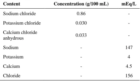
JEOL JDX-8030 XRD system with an accelerating voltage of 30kV, current 20mA and using the CuKα (λ=1.54Å) radiation was used to determine phase structure of the samples. FESEM (TESCAN, Mira3 model) was used for analyzing the thickness and surface morphology of the coatings before and after corrosion tests. EG&G potentiostat/galvanostat (273A model) was used for electrochemical tests that coupled with Frequency Response Analyzer (FRA) (SI 1250 model) for EIS analysis. Electrochemical tests were performed in free air condition in Ringer's solution at room temperature (~25°C). Chemical composition of the Ringer's solution which is a popular solution in biological tests for surgical instruments is presented in Table 2. Osmolality of this solution was 309mOsmol/L. A three electrodes system included Saturated Calomel Electrode (SCE) as reference electrode, platinum mesh as auxiliary electrode and bare and coated 420C SS as working electrodes were used to conduct corrosion tests.
TABLE 1. Chemical composition of used 420C SS in comparison with surgical grade 420C SS
Element Composition (Wt. %) Materials
Fe Ni(max) Cr
Si(max) Mn(max)
C
bal. 1.00 12.5-14.5 1.00
1.00 0.42-0.5 Standard
bal. 0.33 14.3
0.61 0.31
0.45 Substrate
TABLE 2. Chemical composition of the used Ringer's solution
Content Concentration (g/100 mL) mEq/L
Sodium chloride 0.86 -
Potassium chloride 0.030 -
Calcium chloride
anhydrous 0.033 -
Sodium - 147
Potassium - 4
Calcium - 4.5
Chloride - 156
With the aim of measuring the open circuit potential (OCP) for EIS and PDP tests, samples were immeged in Ringer's solution for 30min. 1cm2 of the surface of the specimens were exposed to corrosive solution. The PDP test was done at a scanning rate of 1mV/s in a range of -0.8V to +1.5V vs. SCE to determine the overall anodic/cathodic corrosion characteristics of the coated systems.
Parameters related to PDP test were extracted with using Powersuit software by extrapolation of linear region in the TOEFL range ( ±200mV). The EIS test was conducted in the frequency range of 10mHz to 65kHz with a sine voltage amplitude of 10mV.
Impedance data were obtained by an equivalent that derived graphs from the proposed equivalent circuits and with using Zview2 software. Equivalence of data were carried out with high precision so that parameter value of Chi-squared for all equivalents were less than 0.01.
3. RESULTS AND DISCUSSION
3. 1. Structural and Microscopic Analysis
Figure 1 shows XRD patterns of bare and coated SS. The crystal planes of TiN phase is based on ICSD 00-006-0642 consist of (1 1 1), (2 0 0), (2 2 0), (3 1 1) and (2 2 2), and for CrN phase is based on ICSD 01-076-2494 consist of (1 1 1), (2 0 0) and (3 1 1).
It can be consequent that the multi-layer coating consists of TiN and CrN phases. Due to the low thickness of coating, sharpness of the peaks is weak. Cross-sectional images of FESEM coated samples which confirmed the formation of dense and uniform coatings with 1.5µm in thickness are shown in Figure 2. There is distinct interface between TiN and CrN in multi-layered TiN/CrN coating. The dark layers are TiN and the bright layers are CrN.
Figure 1. XRD patterns of the specimens
a b c
Figure 2. Cross-sectional FESEM images of the coatings a) TiN, b) CrN, c) TiN/CrN
a b
c d
Figure 3. Surface FESEM images of the samples. a) Bare SS, b) TiN, c) CrN, d) TiN/CrN
deposition process. By comparison of the images, it was being proved that surface of CrN coating has less defects like macro-particles and pinholes; thus, was more uniformity.
3. 2. Corrosion Performance
3. 2. 1. PDP Test After measuring of OCP, PDP test was performed to evaluate corrosion resistance properties of the bare and coated 420C SS. Figure 4 represents the Tafel polarization plots for all examined samples after 30min immersion in Ringer's solution at room temperature.
For all the samples, parameters which obtained from extrapolating of PDP curves in Tafel region by Powersuite software, were shown in Table 3.
icorr is an important parameter in the corrosion rate measuring of the specimens. The slope of cathodic branches of the curves in coated specimens is very similar. Corrosion potential (Ecorr) of bare SS was equal to -78.3mV SCE and its curve showed by 120-200mV SCE toward more positive values in comparison to coated specimens. The main reason for nobler potential of the bare SS relative to the coated samples is due to formation of corrosion products like iron oxide on its surface at the first step of the reaction. However, icorr of the coated samples are slightly lower than bare SS. CrN had lowest icorr and corrosion rate in comparison with the coated samples. Further revision of the Tafel regions indicates that the slope of cathodic branch (βc) is variable between -203 and -300mV/dec. In the coated samples,
Figure 4. Polarization curves of the samples
TABLE 3. Parameters which obtained from analysis of Tafel region for all specimens
Sample
Ecorr
(mV vs. SCE)
icorr
(µA/cm2)
Corrosion Rate (mpy)
Rp
(Ω.cm2)
Bare SS -78.3 0.17 0.086 268.1
CrN -279.5 0.09 0.042 593.6
TiN -192.9 0.10 0.050 438.2
TiN/CrN -248.0 0.14 0.068 438.2 1.5µm
macroparticles
reduction of oxygen in the surface show that cathodic process is dominant. The slope of anodic branch (βa) is variable between 164 and 339mV/dec. The lower quantities of βa observed in comparison with the βc prove that the corrosion processes are under cathodic (oxygen reduction) control [13, 20]. The reactions of water and oxygen in the salt environment are according to Reactions (1) and (2) [21]:
2H2O+2e-→2OH-+H2↑ (1)
O2+2H2+4e-→4OH- (2)
It seems that, existence of defects such as macro-particles and pinholes, during corrosion process, are the restrictive factors which can control the corrosion behavior of the coating system at lower anodic potentials. Polarization resistance (Rp) which is measured by Equations (3) and (4) [22] is consist of icorr and Ecorr parameters. Therefore Rp can analyze the corrosion behavior of samples kinetically and thermodynamically. Increasing in Rp value is an important sign for improvement of the corrosion resistance. Bare SS has minimum value of Rp (268.1Ω.cm2) meanwhile single-layered CrN coated sample has maximum Rp value (593.6Ω.cm2). Rp value of multi-layered TiN/CrN and single-layered TiN is equal to 438.2Ω.cm2.
It means that, fabricating of coatings has increased the corrosion resistance of bare SS. The CrN Single-layer has highest Rp and hence the highest corrosion resistance. Table 3, shows the parameters which obtained from Tafel analysis for bare SS and coated specimens.
𝛽 = 𝛽𝑐 . 𝛽𝑎
2.3 (𝛽𝑐+𝛽𝑎) (3)
𝑅𝑝 = 𝛽
𝑖𝑐𝑜𝑟𝑟 (4)
The amount of pores in the surface is an important characteristic that affected corrosion behavior of the coated samples. This parameter is measured with Equation (5) [22]. In Equation (5), F represents the amount of pores, Rps is the polarization resistance of the bare SS, Rp is the polarization resistance of the coated sample, ΔE is the difference between corrosion potential of the coated samples and bare SS and βa is the slope of anodic branch of the bare SS.
𝐹 = 𝑅𝑝𝑠
𝑅𝑝 . 10
(𝛥𝐸
𝛽𝑎) (5)
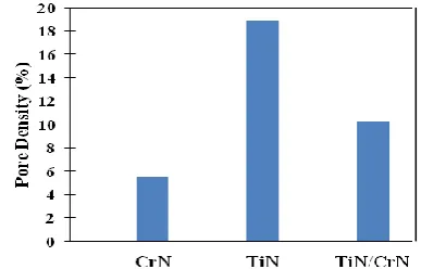
Results are represented in Figure 5. According to Figure 5, it is clear that the CrN coating has lowest pore density percent value equal to 5.5%. These values are 10.3% and 18.9% for TiN/CrN and TiN coatings, respectively.
3. 2. 2. EIS Measurements EIS involved measuring the DC resistance or assigning an equivalent
capacitance at a single frequency. Changes in the capacitance related to the uptake of water so long as changes in the resistance of the coating were analyzed in term of penetration by ionic species from the environment. The measurement of the frequency-dependent impedance leads to more accurate evaluation based on the deviation of the coating impedance from a capacitive response [14, 23].
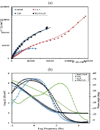
Figure 6 represents the EIS diagrams of bare and coated SS which immersed for 30min in Ringer's solution. In the CrN coated sample, formation of more consecutive semicircles with higher diameter is due to the surface activity and the formation of layers in contact with the electrolyte solution, which led to a reduction in the speed of electrochemical reactions and eventually increased corrosion resistance.
The depression of the semicircle is related to heterogeneity of the electrode surface. Meanwhile, a diffusion process that aims to define a second semicircle at low frequencies was observed.
For studding the resistance and capacitive components of the coatings, the impedance spectrum is modeled by an equivalent circuit using the Zview2 software as shown in Figure 7. Based on Nyquist diagram, Bode and Bode phase diagram and cross-sectional FESEM images, the EIS data can be well explained by equivalent circuit with two time constants for bare SS, TiN and TiN/CrN coated samples and with resistance of electrolyte test solution and CPE that is Constant Phase Element. In bare SS, TiN coating and TiN/CrN coating, CPE1 and R1 parameters are used in parallel to replace the dielectric properties of the oxide layer (for bare SS) and coatings (for TiN and TiN/CrN coating). CPE2 and R2 elements in parallel are attributed to characterize charge transfer in the coating/substrate interface. Whilst in CrN coating, CPE1 and R1 as well as CPE2 and R2 parameters are used in parallel to replace the dielectric properties of the coating. CPE3 and R3 parameters are in parallel to describe electric inter-layer were seen only in CrN coated sample. In general, coated samples have a higher corrosion resistance compared to bare SS. CrN coated sample has the highest dual layer
(a)
(b)
Figure 6. EIS diagrams for all samples. a) Nyquist, b) Bode and Bode phase
(a)
(b)
Figure 7. Equivalent circuit of different coatings (a) Bare SS, TiN and TiN/CrN (b) CrN
resistance (R2 parameter). While TiN/CrN and TiN coated specimens have the same resistance. In fact, the corrosion reactions have begun in the area of defects in coatings with micro-sized dimensions such as surface cracks and cavities. Also the speed of corrosion reactions caused by the presence of chlorine ions in the solution has increased. In Figure 6, the similarity of the behavior of TiN and TiN/CrN coated samples is clearly visible.
C2 is known as coating capacity that is an important parameter for determining of the corrosion behavior. As the density of the coating increases, the penetration of the corrosive electrolyte decreases. Thus, according to the depression of obtained Nyquist graphs (in order to convert the constant phase element) and Equation (6), C2 is calculated [23]:
𝐶2=
(𝑅2𝐶𝑃𝐸)
1 𝑛 ⁄
𝑅2
(6)
In which CPE is non-ideal capacity, R2 is the resistance and n is represents the capacity factor. Figure 8 is represent the logarithmic variation of C2. Ion exposures in coating/substrate interface of CrN and TiN/CrN samples are less than the others. As a result, these coatings exhibit higher corrosion resistance.
The total polarization resistance (Rp) is equal to sum of the all resistances that derived from EIS test. Rp can be considered as an index of corrosion resistance that is inversely fits with the corrosion rate [13]. Used parameters for fitting of impedance data are stated in Table 4.
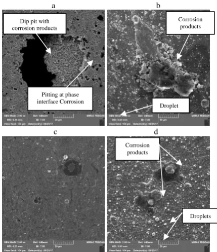
3. 2. 3. Surface FESEM Analysis Figure 9 shows the surface morphology of the samples after corrosion tests in Ringer's solution. In surface of the bare SS, local passive film breaks down and thus allow to occurring the significant corrosion. This feature is called pitting corrosion that occurs when portions of the metal surface lose their passivity and dissolved rapidly. Presence of the Cl- ion in electrolyte as an oxidizing agent can strongly affect this type of corrosion [24, 25]. Surface of the bare SS is contain of deep pits, corrosion products and pits at phase interface which show that bare SS was corroded more than the other specimens in Ringer's solution.
FESEM images of the coated samples confirm that selective corrosion takes place at growth defect areas. A macro-particle is compositionally metal rich and
Figure 8. Logarithmic variation of C2 for all samples
TABLE 4. Used parameters for fitting of impedance data in examined samples
Sample (Ω.cmR1 2)
CPE1 R2
(Ω.cm2)
CPE2 R3
(Ω.cm2)
CPE3 Rp
(Ω.cm2)
n n n
Bare SS 102.8 0.29 50018 0.91 - - 268.1
CrN 28.4 0.58 27426 0.96 118025 0.76 593.6
TiN 282.1 0.86 74027 0.85 - - 425.7
nitrogen deficient. This defect is anodic with respect to both surrounding coating and can act as preferential sites for the diffusion of aggressive ions present in the electrolyte in contact with the CAE coated metal such as chlorides. This can lead to localized corrosion attack [14, 26]. On the other hand, pinholes can accelerate penetration of the electrolyte underneath of the coating and lead to increase of the substrate corrosion.
CrN coated sample has lowest corrosion rate and minimal damage due to less dispersion of defects on the surface. Results of corrosion tests and surface FESEM images were confirmed this opinion. Figure 9 (b) and (d) shows severe localized corrosion causing by macro-particles in TiN coated and TiN/CrN coated samples. Whilst there are no cracking on the surface of single-layered CrN coated sample.
Present study showed that coated samples represent better corrosion behavior against aggressive chloride ions (Cl-) in comparison with bare SS. Corrosion products are specified in Figure 9.
The surface FESEM images before and after corrosion tests confirm that the single-layer CrN coated sample has dense structure and fine smooth crystallites without any pores and cracks. These features lead to less penetrability against corrosive solution and thus stability of this sample. A scarcity of upright diffusion channels because of the non-columnar structure wherewithal the oxygen diffusion rate is considerably reduced.
Although coatings process reduces the totality dissolution rate, the corrosion process of the coated SS is still under influence of relatively rapid local dissolution of the substrate at through-coating pinholes. This feature is most visible in TiN coated and TiN/CrN coated samples.
Results of electrochemical tests show that the corrosion process in the TiN coated and TiN/CrN coated specimens has different stages. When the Ringer's solution reaches the pinholes, due to the difference in the binding energy and chemical composition between the coating matrix and droplet or substrate, galvanic corrosion cells are formed. With the development of localized corrosion, corrosion products such as oxide compounds and calcium compounds could fill the micro-pores temporarily and consequently prevent further corrosion. Anyway, the natural features of the TiN coated and TiN/CrN coated samples lead corrosion demolition basically caused by the autocatalytic effect in the examined solution [11, 27].
Compact structure of the single-layer CrN coating can redistribute the current flow and eliminate current concentration at the small pinholes and prevent rapid galvanic attack at the pits. Moreover, corrosion rust fills the micro-corrosion holes more efficiently. Subsequently the long-term electrochemical stability of the CrN coated sample is happened.
a b
c d
Figure 9. Surface FESEM micrographs for samples with degradation a) Bare SS, b) TiN, c) CrN, d) TiN/CrN
4. CONCLUSION
In present study micro-structural and corrosion behavior of the single-layered TiN, single-layered CrN and multi-layered TiN/CrN coating deposited by CAE method on
420C SS substrates was investigated. The
electrochemical appraisal in Ringer's solution was done by EIS and PDP methods.
The following results are deduced from this research: - Coated samples have better corrosion manner against chloride ions (Cl-). It means that the fabrication of coating increase the corrosion potential to more positive potential quantities and consequently protects bare SS from further corrosion.
- Based on PDP results, single-layered CrN had maximum Rp value (593.6Ω.cm2), minimum corrosion rate (0.042mpy), lowest pore density percent value (5.5%) and thus better corrosion performance compared to coated samples.
- EIS data confirm that, TiN and TiN/CrN coatings can be well described by equivalent circuit with two times constants while CrN coating well depicted by equivalent circuit with three times constants. Logarithmic variation of C2 that shows the ion exposures to the coating/substrate interface for CrN coated sample less than the other specimens. - The FESEM images before and after corrosion tests
confirmed that the single-layer CrN coated sample has a dense structure and fine smooth crystallites without any pores and cracks. These features lead to
Dip pit with corrosion products
Pitting at phase interface Corrosion
Corrosion products
Droplet
Corrosion products
less penetrability against the corrosive solution and thus stability of this sample.
- Finally, In terms of interfacial conductivity, corrosion resistance, electrochemical stability, simplicity of modification technology, non-toxicity and low material cost, the single-layer CrN coated SS could be a good candidate for application in general surgical instruments.
5. REFERENCES
1. Novinrooz, A. J. . A. N. and S. H., “Improvement of hardness and corrosion resistance of SS-420 by Cr+TiN coatings”, Journal of
Achievements in Materials and Manufacturing Engineering,
Vol. 23, No. 1, (2007), 43–46.
2. Sugumaran, A.A., Purandare, Y., Ehiasarian, A.P., and Hovsepian, P.E., “Corrosion behavior of post-deposition polished droplet-embedded arc evaporated and droplet-free high power impulse magnetron sputtering/direct current magnetron sputtering coatings”, Corrosion, Vol. 73, No. 6, (2017), 685–693. 3. D’Avico, L., Beltrami, R., Lecis, N., and Trasatti, S.P.,
“Corrosion Behavior and Surface Properties of PVD Coatings for Mold Technology Applications”, Coatings, Vol. 9, No. 1, (2018), 1–12.
4. Singh, P.K., Kumar, A., Sinha, S.K., Aggarwa, A. and Sing, G.P., “Improvement in surface properties with TiN thin film coating on plasma nitride austenitic 316 stainless steel”, International
Journal of Engineering and Technology, Vol. 8, No. 1, (2016),
350–356.
5. Akbarzadeh, M. Shafyei, A., and Salimijazi, H.R.,, “Characterization of TiN, CrN and (Ti, Cr) N coatings deposited by cathodic arc evaporation”, International Journal of
Engineering - Transactions A: Basics, Vol. 27, No. 7, (2014),
1127–1132.
6. Malarvannan, R.R., Moorthy, T.V., Sathish, S., and Hariharan, P., “Investigation on the corrosion behavior of physical vapor deposition coated high speed steel”, Advances in Mechanical
Engineering, Vol. 7, No. 8, (2015), 1–5.
7. Ajiboye, O.J., “Surface defects characterization and electrochemical corrosion studies of TiAlN, TiCN and AlCrN PVD coatings”, Master Thesis, Tallinn University of Technology, Estonia, (2016).
8. Azadi, M., Sabour Rouhaghdam, A., and Ahangarani, S., “A Review on Titanium Nitride and Titanium Carbide Single and Multilayer Coatings Deposited by Plasma Assisted Chemical Vapor Deposition”, International Journal of Engineering -
Transactions B: Applications, Vol. 29, No. 5, (2016), 677–687.
9. Jakovljević, S., Alar, V., and Ivanković, A., “Electrochemical Behaviour of PACVD TiN-Coated CoCrMo Medical Alloy”,
Metals, Vol. 7, No. 7, (2017), 1–14.
10. Poursaiedi, E. and Salarvand, A., “Comparison of properties of ti/tin/ticn/tialn film deposited by cathodic arc physical vapor and plasma-assisted chemical vapor deposition on custom 450 steel substrates”, International Journal of Engineering - Transaction
A: Basics, Vol. 29, No. 10, (2016), 1459–1468.
11. Cegil, O. Kiling, B., Sen, S., and Sen, U., “Corrosion Properties of CrAlN and TiAlN Coatings Deposited by Thermoreactive Deposition Process”, Acta Physica Polonica, Vol. 125, No. 2, (2014), 359–361.
12. Cedeño-Venté, M. L. Espinosa-Arbeláeza, D.G., Manríquez-Rochab, J., Rodrígueza, G.C.M., Gómez-Ovallea, A.E., González-Hernándeza, J., and Alvarado-Orozcoa, J.M., “Effect of
Graded Bias Voltage on the Microstructure of arc-PVD CrN Films and its Response in Electrochemical & Mechanical Behavior”, Applied Physics, (2018), 1–14.
13. Ward, L. Pilkington, A., and Dowey, S., “Studies on the Effect of Arc Current Mode and Substrate Rotation Configuration on the Structure and Corrosion Behavior of PVD TiN Coatings”,
Coatings, Vol. 7, No. 4, (2017), 1–15.
14. Bouzid, K., Beliardouh, N.E., and Nouveau, C., “Wear and corrosion resistance of CrN-based coatings deposited by RF magnetron sputtering”, Tribology in Industry, Vol. 37, No. 1, (2015), 60–65.
15. Lin, M.T., Wan, C.H., and Wu, W, “Enhanced corrosion resistance of ss304 stainless steel and titanium coated with alternate layers of TiN and ZrN in a simulated O2 rich environment of a unitized”, International Journal of
Electrochemical Science, Vol. 9, (2014), 7832–7845.
16. Hedayati, A., Asghari, S., Alinoori, A.H., Koosha, M., and Vuorinen, E., “Effects of coating thickness on corrosion and contact resistance behavior of TiN coated AISI 316L as bipolar plates for PEMFC”, Iranian Journal of Hydrogen & Fuel Cell, Vol. 3, No. 2, (2017), 137–149.
17. Keawhan, C., Wongpanya, P., Witit-anun, N., and Songsiriritthigul, P., “Corrosion Behavior of AISI 4140 Steel Surface Coated by Physical Vapor Deposition”, Journal of
Metals, Materials and Minerals, Vol. 22, No. 1, (2012), 69–76.
18. Perillo, P.M., “Corrosion behaviour of titanium nitride coating on Titanium and Zircaloy-4”, American Journal of Materials
Science and Application, Vol. 3, No. 2, (2015), 18–25.
19. Aperador, W., Delgado, A., and Duque, J., “Corrosion Resistanne of the [TiN/CrN]n Coatings Deposited on Steel AISI 4140”,
International Journal of Electrochemical Science, Vol. 8,
(2013), 10711–10719.
20. Liu, Y., Gao, Z. , Lu, X., and Wang L., “Effect of Temperature on Corrosion and Cathodic Protection of X65 Pipeline Steel in 3.5% NaCl Solution”, International Journal of Electrochemical
Science, Vol. 14, (2019), 150–160.
21. Loveday, D., Peterson, P. and Rodgers, B., “Evaluation of organic coatings with electrochemical impedance spectroscopy, Part 3: Protocols for testing coatings with EIS”, Journal of Chemical
Technology, Coatings Technology, Vol. 2, No. 13, (2005), 22–
27.
22. Loveday, D., Peterson, P. and Rodgers, B., “Evaluation of organic coatings with electrochemical impedance spectroscopy, Part 1: Fundamentals of Electrochemical Impedance Spectroscopy”,
Journal of Chemical Technology, Coatings Technology, Vol. 8,
(2004), 46–52.
23. Suo, X., Guo, C., Kong, Decheng., and Wang, L., “Corrosion behaviour of TiN and CrN coatings produced by magnetron sputtering process on aluminium alloy”, International Journal of
Electrochemical Science, Vol. 14, (2019), 826–837.
24. Kucuk, I. and S.C., “Pitting corrosion of TiN-coated stainless steel in 3% NaCl solution”, Materiali in Tehnologije, Vol. 49, No. 2, (2015), 183–192.
25. Caiazzo, F.C., Sisti, V., Trasatti, S.P., and Trasatti, S., “Electrochemical characterization of multilayer Cr/CrN-based coatings”, Coatings, Vol. 4, No. 3, (2014), 508–526.
26. Antunes, R.A., De Lima, N.B., De Almeida, Rizzutto, M., Higa, O.Z., Saiki, M., and Costa, I., “Surface interactions of a W-DLC-coated biomedical AISI 316L stainless steel in physiological solution”, Journal of Materials Science: Materials in Medicine, Vol. 24, No. 4, (2013), 863–876.
Corrosion Behavior of TiN/CrN Nanoscale Multi-layered Coating in Ringer's Solution
G. Faghania, S. M. Rabieeb, S. Nourouzib, H. Elmkhahc
a Department of Mechanical Engineering, Babol Noshirvani University of Technology, Babol, Iran b Department of Materials Engineering, Babol Noshirvani University of Technology, Babol, Iran c Department of Materials Engineering, Bu-Ali Sina University, Hamedan, Iran
P A P E R I N F O
Paper history:
Received 06 April 2019
Received in revised form 28 October 2019 Accepted 07 November 2019
Keywords: 420C Stainless Steel Corrosion Multi-layer Ringer's Solution TiN/CrN
هديكچ
ششوپ یگدروخ راتفر ،هلاقم نیا رد کت یاه
هیلا یا TiN و CrN هیلادنچ و یا TiN/CrN دلاوف یور رب هدش داجیا
گنز نزن C 420 هب نومزآ اب ییایمیشورتکلا یسررب .دش هعلاطم رگنیر لولحم رد یدتاک سوق یریخبت شور نویسازیرلاپ یاه
فیط و کیمانیدویسناتپ یجنس
هک درک دییأت کیمانیدویسناتپ نویسازیرلاپ نومزآ جیاتن .تفرگ ماجنا ییایمیشورتکلا سنادپما
همه هنومن ی هدودحم رد( نویسازیرلاپ تمواقم ریداقم رد شیازفا یاراد ،هدش هداد ششوپ یاه ی
2 cm Ω. 593.6 -438.2 رد )
هنومن اب هسیاقم گنز دلاوف ی
( ششوپ نودب نزن 2
cm Ω. 268.1 م .دندوب ) هنومن یارب یگدروخ خرن ریداق گنز دلاوف یاه
نزن
ششوپ ،ششوپ نودب کت یاه
هیلا یا CrN و TiN هیلادنچ و یا TiN/CrN اب ربارب بیترت هب
0.086 ، 0.042 ، 0.050 و
0.068 هزادنا لاس رد چنیا یلیم فیط نومزآ جیاتن .دش یریگ
کت ششوپ هک داد ناشن زین ییایمیشورتکلا سنادپما یجنس لا
هی یا
CrN لداعم ینامز تباث هس اب یرادم اب یبوخ هب نازیم نیرتلااب لاح نیع رد و رتلااب سنادپما ریداقم یاراد و هدش یزاس
( یمتیراگل رییغت 2
C ) هنومن ریاس هب تبسن کت ششوپ هک درک دییأت یگدروخ درکلمع جیاتن ،تیاهن رد .دوب اه
هیلا یا CrN
رب دربراک یارب یبسانم باختنا گنز دلاوف یور
نزن C 420 یم یمومع یحارج یاهرازبا رد دربراک فده اب .دشاب