Please cite this article as: M. Safari, J. Joudaki, Y. Ghadiri, A Comprehensive Study of the Hydroforming Process of Metallic Bellows: Investigation and Multi-objective Optimization of the Process Parameters, International Journal of Engineering (IJE), IJE TRANSACTIONS B: Applications Vol. 32, No. 11, (November 2019) 1681-1688
International Journal of Engineering
J o u r n a l H o m e p a g e : w w w . i j e . i r
A Comprehensive Study of the Hydroforming Process of Metallic Bellows:
Investigation and Multi-objective Optimization of the Process Parameters
M. Safari*, J. Joudaki, Y. Ghadiri
Department of Mechanical Engineering, Arak University of Technology, Arak, Iran
P A P E R I N F O
Paper history: Received 29 April 2019
Received in revised form 16 August 2019 Accepted 12 September 2019
Keywords:
Hydroforming Process Metallic Bellows
Response Surface Methodology Mathematical Model Multi-objective Optimization
A B S T R A C T
In this paper, for the first time, a comprehensive experimental study is performed on hydroforming process of metallic bellows. For this purpose, the effects of the main process parameters and their interactions on the characteristics of hydroformed metallic bellows are investigated using Response Surface Methodology (RSM). The selected parameters as input variables are internal pressure, die stroke and die fillet. The measured characteristics of metallic bellows are convolution height and thickness of the top point of bellows congress. A set of experiments are carried out and the convolution height and thickness of the top point of bellows congress are measured. Then a mathematical model is developed according to the second-order linear regression equations to maximize the convolution height and thickness of the top point of bellows congress. The results show that the increase in the convolution height and decrease in the thickness of the top point of bellows congress will occur by increasing the internal pressure and die stroke. Also, the convolution height and thickness of the top point of bellows congress are increased with an increase in the die fillet.
doi: 10.5829/ije.2019.32.11b.19
1. INTRODUCTION1
Hydroforming process is used for forming and shaping the sheets or tubes into the desired shape by applying a controlled hydraulic pressure. The die cavity determined the final shape, while the pre-form sheet or tube is conformed to the die cavity shape. In recent years, several types of research have been reported on the tube hydroforming process. For example, in 2018, Chen et al. [1] investigated the tube hydroforming process and its microstructural and mechanical effects. The pure copper tube is annealed and hydroformed. Their results verified that a considerable grain refinement will be happened due to the induced plastic deformation and High Angle Grain Boundaries (HAGB) convert to the Low Angle Grain Boundaries (LAGB) by increasing the induced strain in tube hydroforming. In 2018, Engaile and Lowrie [2] studied the feasibility of Micro-tube hydroforming by finite element analysis. The FE results show that specific design of die and a notched punch
*Corresponding Author Email: [email protected] (M. Safari)
can bear will be observed by increasing the number of layers, but the decrease is limited. Bellows are mechanical parts developed to compensate the expansions and mechanical movement of parts in piping systems. The bellows are symmetrical shells consisting of corrugated meridians in the middle of the tube. The corrugated meridians provide the flexibility of movement required to absorb mechanical vibration or translational movement. The bellows are used extensively in industrial applications such as power plants, petroleum installations, heat exchangers, and automotive parts. Bellows are usually used in vacuum pumps and joint expansions and sealing valves and the equipment used to prevent the seismic loading damage [6]. The bellows can be used for thermal strain compensation due to the high or low temperature gradient. The bellows can be investigated from two view-points. Firstly, their behavior under loading conditions and in the second place, the manufacturing technology of the bellows. Belyaev et al. [7] describe the stress-strain state of the bellows while under elastic loading. Theoretical formulations are developed based on classical shell theory. The results can predict the buckling of the bellows while working. Also, due to the application and loading condition of the bellows, the fatigue life of the bellows is important and it can affect the operation of the bellows [8]. The hydroforming process is the finest manufacturing method for fabricating metallic bellows. Despite the complications in their manufacturing by the hydroforming process, high-quality metallic bellows can be produced by proper controlling of the material flow. The literature survey shows that researches in the field of manufacturing of bellows by hydroforming process are very low in comparison with the other hydroforming researches. Some of the reported researches in the field of the hydroforming process of metallic bellows are listed in the following. In 2010, Hashemi et al. [9] developed a model to predict the initiation of necking according to the use of Forming Limit Diagram (FLD) and the Forming Limit Stress Diagram (FLSD) and Marciniak and Kuczynski (M–K) model. The experimental and theoretical results indicated that the proposed model predicts the necking in tube hydroforming process with acceptable accuracy. In 2009, Faraji et al. [10] investigated the effect of process parameters as initial length of the tube, the internal pressure, axial feed rate and magnitude of axial feed, and the mechanical properties of materials in the manufacturing of the metallic bellows by finite element analysis (FEA) and experimental measurements. The finite element analysis consists of two different steps: an explicit run for modeling the tube hydroforming and an implicit run for prediction of the springback in the component. A good agreement was found between the numerical results and experimental measurements. In 2007, Kang et al. [11]
combined the axial movement and pressure increase to fabricate metallic bellows by tube hydroforming process. In this way, the bellows with different die profiles including rectangular, circular, and triangular was created in a single step. Several studies have been implemented by a research team in Babol Noshirvani University of Technology [12-15]. They showed that the metallic bellows can be manufactured by closed and open die tube hydroforming. The results show that the effect of pressure path on forming bellows in both stages is important and its effect on the occurrence of bursting or wrinkling defects can be investigated by finite element simulation. Furushima et al. [16] developed a novel semi-dieless forming process with local induction heating and axial compression to fabricate the metallic bellows. The results show that the convolution height can be controlled by compression ratio (the ratio of compression velocity to the feeding velocity). Wang et al. [17] implemented the superplastic forming (SPF) method to fabricate metallic bellows from Ti–6Al–4V alloy. During the SPF process, the tubular blank is restrained in a multi-layer die block assembly and the bellows formed by applying pressurized gas and compressive axial load. The forming load route is divided into three steps in order to obtain optimum thickness distribution.
The main problem in the fabrication of metallic bellows is the selection of hydroforming process parameters in order to fabricate fault-free and
outstanding components. For producing new
selected main tube hydroforming input parameters (internal pressure, die stroke and die fillet) to the main characteristics of hydroformed metallic bellows such as convolution height and minimum thickness. Then, the optimal hydroforming condition will be found to maximize the convolution height and decrease the thickness reduction of the hydroformed metallic bellows.
2. EXPERIMENTAL METHOD
The selected material for fabrication of the bellows is AISI 304 austenitic stainless steel. Table 1 shows the chemical composition of AISI 304 stainless steel. The initial thickness and diameter of the AISI 304 tube are 0.6 mm and 51mm, respectively.
The proposed hydroforming process for
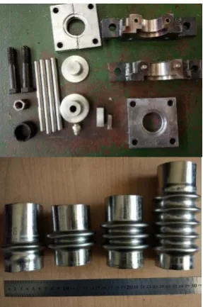
manufacturing of metallic bellows consists of two steps as bulging and tube folding. In the first step, tube-bulging will be done to form a preform specimen. A die consisting of equally spaced circular plates is positioned around the tube which helps to form the tube. The internal pressure will be increased until the contact between the tube and the die surfaces are obtained. In this situation the preform is constrained at contact surfaces, Hence, the tube has bulged through the equally spaced plates in the die. In the second step, an axial force will be applied to fold the bulged tube. The internal pressure is still kept to complete the final shape of the bellows. The quality of the manufactured bellows is dependent on these two forming steps. Figure 1 shows a schematic view of the die, the prepared die set and some of the metallic bellows manufactured by the hydroforming process.
The most important parameters affecting the characteristics of the hydroformed specimens are internal pressure, die stroke and die fillet. In addition, the convolution height and thickness are the main features in metallic bellows that affect the performance of bellows in industrial applications. As it is seen in Figure 2, in hydroformed metallic bellows the maximum convolution height and minimum thickness always will appear at the top point of bellows congress. This point experiences maximum deformation and the highest amount of bending stresses. Hence, the top point of bellows congress is one of the most critical points in
TABLE 1. Chemical composition of 304 stainless steel tube
Component Fe C Cr Ni
Weight (%) 66-74 0.08 18-20 8-10.5
Mn Si P S
2 1.00 0.045 0.03
Figure 1. The die set and some of the metallic bellows
manufactured by the hydroforming process
Figure 2. Maximum convolution height and minimum
thickness in the top point of bellows congress
the metallic bellows and failure can happen in this point due to unallowable thickness reduction. So, in this research, convolution height and thickness at the top point of bellows congress will be measured as characteristics of the hydroformed bellows.
fabricated based on 15 different sets of parameters. For each set of parameters, a new bellows is manufactured. Then, the part cut from the middle surface by Wire-EDM (wire cut). The convolution height and thickness at the top point of the bellows congress are measured and reported in Table 3.
3. RESULTS AND DISCUSSION
After measuring the convolution height and the thickness at the top point of the bellows congress, the analysis of variance (ANOVA) is performed for the results of Table 3. The results of ANOVA are shown in Tables 4 and 5.
The ANOVA is performed by choosing a 95% reliability for the studied applications. The last column of Tables 4 and 5 (P-value) determines the effectiveness of the parameters (It should be less than 0.05). The F-value in ANOVA shows the effectiveness of an input
TABLE 2. The selected levels of parameters for the study
Parameter Units Symbols Limits
Internal pressure bar P 90 110 130
Die stroke mm L 10 12 14
Die fillet mm R 2 3 4
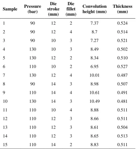
TABLE 3. The experiments plan and measured convolution
height and thickness of hydroformed bellows
Sample Pressure (bar)
Die stroke
(mm) Die fillet (mm)
Convolution height (mm)
Thickness (mm)
1 90 12 2 7.37 0.524
2 90 12 4 8.7 0.514
3 90 10 3 7.27 0.521
4 130 10 3 8.49 0.502
5 130 12 2 8.34 0.510
6 110 10 2 6.95 0.527
7 130 12 4 10.01 0.487
8 90 14 3 8.98 0.507
9 110 14 4 10.61 0.491
10 130 14 3 10.49 0.481
11 110 10 4 8.88 0.511
12 110 12 3 8.66 0.511
13 110 12 3 8.61 0.504
14 110 12 3 8.65 0.513
15 110 14 2 8.83 0.511
parameter. The higher magnitude for F-value means higher effectiveness of the parameter.
One of the main advantages of ANOVA is developing a regression equation for output parameters. The quality of prediction can be assessed by the value of the prediction error sum of squares (PRESS). A model with a small value of PRESS is an appropriate and reliable predictor. In this study, the minimum value of PRESS among different models available in the software was observed in a full quadratic model for both convolution height and thickness at the top point of bellows congress. The minimum value of PRESS for convolution height and the thickness at the top point of bellows congress are 5.7328 and 0.000052mm, respectively. The convolution height and the thickness at the top point of bellows congress of hydroformed metallic bellows are presented in Equations (1) and (2), respectively.
TABLE 4. The results of ANOVA for convolution height
Terms DF Seq SS Adj SS Adj MS F P
Model 9 62.6022 62.6022 6.9558 97.07 0.000
P 1 12.55 12.55 12.55 175.13 0.000
L 1 26.7912 26.7912 26.7912 373.87 0.000
R 1 22.512 22.512 22.512 314.15 0.000
1 0.0286 0.0156 0.0156 0.22 0.660
1 0.4907 0.4785 0.4785 6.68 0.049
1 0.0075 0.0075 0.0075 0.1 0.760
1 0.0841 0.0841 0.0841 1.17 0.328
1 0.1156 0.1156 0.1156 1.61 0.260
1 0.0225 0.0225 0.0225 0.31 0.599
TABLE 5. The results of ANOVA for thickness at the top
point of bellows congress
Terms DF Seq SS Adj SS Adj MS F P
Model 9 0.002364 0.002364 0.000263 404.05 0.000
P 1 0.000925 0.000925 0.000925 1422.31 0.000
L 1 0.00063 0.00063 0.00063 969.42 0.000
R 1 0.000595 0.000595 0.000595 915.58 0.000
1 0.000082 0.000083 0.000083 128.17 0.000
1 0.000051 0.000045 0.000045 69.59 0.000
1 0.000023 0.000023 0.000023 35.5 0.002
1 0.000012 0.000012 0.000012 18.85 0.007
1 0.000042 0.000042 0.000042 65 0.000
R) × (L 0.0375 -R) × +0.00850(P
L) × 0.00362(P +
R -0.045
L 0.0900 + P -0.000162
R 1.46 + L 1.531 -P +0.0294
62.05 = height n convolutio ximum
2
2 2
Ma
(1)
R) × (L 0.000500
-R) × 0.000163(P
-L) × 0.000044(P
-R 0.002500 +
L -0.000875
P 0.00012 -R 0.00025 + L +0.02288
P +0.003088 0.2727
= thickness ximum
2 2
2
Ma
(2)
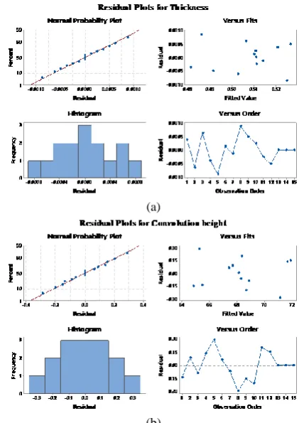
Figure 3 shows the residual plots for Equation (1) and (2). The values of R-sq=99.43%, R-sq (pred)=90.89%, sq (adj)=98.41% for convolution height and R-sq=99.86%, R-sq (pred)=97.80%, R-sq (adj)=99.62% for thickness at the top point of bellows congress. The high magnitude of residuals determines that the second-order linear regression model can predict the output parameter by an acceptable accuracy.
3. 1. The Effects of Process Parameters on Thickness and Convolution Height Figure 4 shows the main effects plots for thickness and convolution height. The internal pressure and the die stroke decrease the mean value of thickness while the die fillet increases the thickness at the top point of bellows congress.
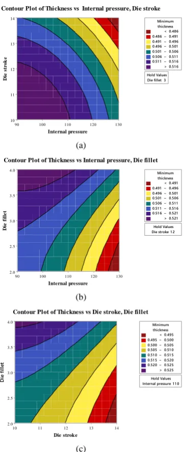
As it is seen in Figure 4, with an increase in internal pressure and die stroke, due to the increase in deformation of hydroformed bellows, the thickness of top point of bellows congress is decreased. In addition, it can be concluded from Figure 4 that the thickness at the top point of bellows congress is increased by increasing the die fillet. This is due to a decrease in the stress concentration. Figure 5 shows the variation of thickness at the top point of bellows congress by changing the input variables. Figure 5 is plotted according to the developed model by RSM. As it is seen in these plots, the thickness at the top point of bellows congress is decreased with increasing the internal pressure and die stroke as well as decreasing the die fillet.
The main effects of process parameters (pressure, die stroke and die fillet) on convolution height of the top point of bellows congress are presented in Figure 6. It is proved from Figure 6 that with increasing the internal pressure and die stroke, the convolution height of the top point of bellows congress is increased due to the increase in deformation of hydroformed bellows. In addition, the convolution height can be increased with an increase in die fillet, due to decreasing in the stress
concentration and consequently delaying in the rapture of the tube.
Figure 7 shows the variation of convolution height with different input variables using the developed model obtained from the RSM method. As it is seen in these plots, the convolution height at the top point of bellows congress is increased with increasing the internal pressure, die stroke and die fillet.
(a)
(b)
Figure 3. Normal probability plots for a- Convolution height;
b- Thickness the top point of bellows congress
Figure 4. The effects of process parameters on the thickness at
Die fillet 3 Hold Values Internal pressure D ie s tr o k e 130 120 110 100 90 14 13 12 11 10 > – – – – – – < 0.486 0.486 0.491 0.491 0.496 0.496 0.501 0.501 0.506 0.506 0.51 1 0.51 1 0.51 6 0.51 6 thickness Minimum
Contour Plot of Thickness vs Internal pressure, Die stroke
(a)
Die stroke 1 2Hold Values
Internal pressure D ie f il le t 130 120 110 100 90 4.0 3.5 3.0 2.5 2.0 > – – – – – – < 0.491 0.491 0.496 0.496 0.501 0.501 0.506 0.506 0.51 1 0.51 1 0.51 6 0.51 6 0.521 0.521 thickness Minimum
Contour Plot of Thickness vs Internal pressure, Die fillet
(b)
Internal pressure 1 1 0Hold Values
Die stroke D ie f ill et 14 13 12 11 10 4.0 3.5 3.0 2.5 2.0 > – – – – – – < 0.495 0.495 0.500 0.500 0.505 0.505 0.51 0 0.51 0 0.51 5 0.51 5 0.520 0.520 0.525 0.525 thickness Minimum
Contour Plot of Thickness vs Die stroke, Die fillet
(c)
Figure 5. The behavior of the minimum thickness at the
top point of bellows congress with different input variables
Figure 6. The effects of process parameters on the
convolution height
Die fillet 3 Hold Values Internal pressure D ie s tr o k e 130 120 110 100 90 14 13 12 11 10 > – – – – – – < 7.4 7.4 7.9 7.9 8.4 8.4 8.9 8.9 9.4 9.4 9.9 9.9 1 0.4 1 0.4 height convolution
Maximum
Contour Plot of Convolution height vs Internal pressure, Die stroke
Die stroke 1 2 Hold Values Internal pressure D ie f il le t 130 120 110 100 90 4.0 3.5 3.0 2.5 2.0 > – – – – – – < 7.6 7.6 8.0 8.0 8.4 8.4 8.8 8.8 9.2 9.2 9.6 9.6 1 0.0 1 0.0 height convolution
Maximum
Contour Plot of Convolution height vs Internal pressure, Die fillet
Internal pressure 1 1 0Hold Values
Die stroke D ie f il le t 14 13 12 11 10 4.0 3.5 3.0 2.5 2.0 > – – – – – – < 7.5 7.5 8.0 8.0 8.5 8.5 9.0 9.0 9.5 9.5 1 0.0 1 0.0 1 0.5 1 0.5 height convolution
Maximum
Contour Plot of Convolution height vs Die stroke, Die fillet
Figure 7. The behavior of the convolution height at the top
point of bellows congress with different input variables
3. 2. Optimization From Figures 4 and 6 it can be concluded that increasing the hydroforming pressure and die stroke lead to a decrease in the thickness and increase in the convolution height. So, multi-objective optimization is needed to find the best manufacturing conditions of the hydroforming process. Table 6 shows the results of statistical optimization made by the RSM method. RSM optimization uses the Derringer and Suich method for optimization.
TABLE 6. Comparison of regression model and experimental measurement
Optimization parameter Internal pressure (bar) Die stroke (mm) Die fillet (mm) Convolution height (mm) Thickness (mm)
Regression Model 100 10 2 9.31 0.51
Experiment 100 10 2 9.12 0.48
%Error 2.04 5.88
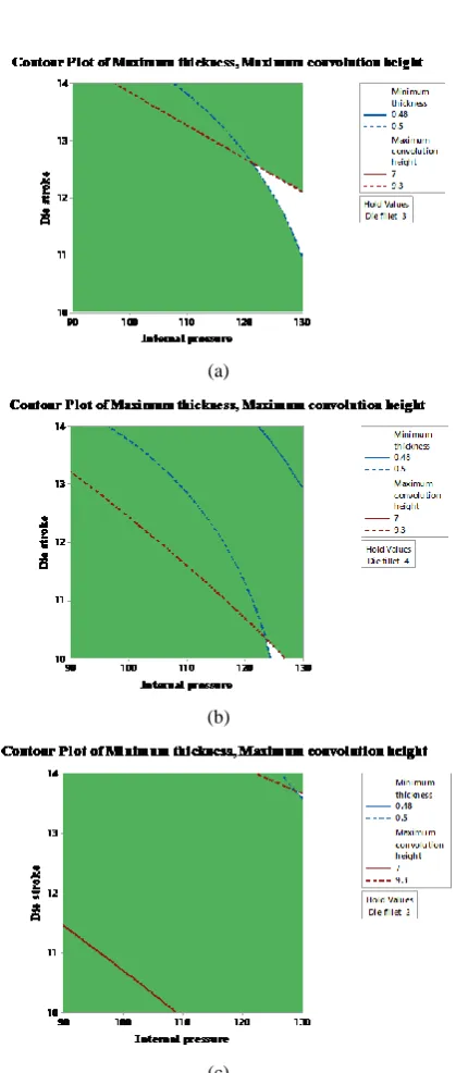
(a)
(b)
(c)
Figure 8. The allowable range of variables for achieving the
maximum thickness and convolution height at the top point of bellows congress for die fillet of (a) 3 mm, (b) 4.0 mm, and (c) 2.0 mm
4. CONCLUSIONS
In this paper, for the first time, a comprehensive experimental investigation was performed on hydroforming process of metallic bellows. The effects of selected process parameters and their interactions on the characteristics of hydroformed metallic bellows were studied using response surface methodology (RSM). The input variables were internal pressure, die stroke and die fillet. The measured characteristics of metallic bellows were convolution height and thickness at the top point of bellows congress. The results showed that the thickness at the top point of the bellows congress was decreased by increasing the internal pressure and die stroke, due to the increase in the deformation of hydroformed bellows. Also, it was concluded that the thickness at the top point of bellows congress was increased with increasing the die fillet, due to decreasing the stress concentration. It was proved that the convolution height of the top point of bellows congress was increased with increasing the internal pressure and die stroke, due to the increase in deformation of hydroformed bellows. In addition, it was indicated that the convolution height could be increased with an increase in die fillet, due to decreasing in the stress concentration and consequently delaying in the rapture of the tube. According to multi-objective optimization, the safe area was extracted to choose internal pressure and die stroke for different die fillets based on the allowable range of variables for obtaining the maximum thickness and convolution height at the top point of bellows congress.
5. REFERENCES
1. Chen, M., Xiao, X., Guo, H. and Tong, J., “Deformation behavior, microstructure and mechanical properties of pure copper subjected
to tube hydroforming”, Materials Science and Engineering: A,
Vol. 731, (2018), 331–343.
2. Engaile, G. and Lowrie, J., “Punch design for floating based
micro-tube hydroforming die assembly”, Journal of Materials Processing
Technology, Vol. 253, (2018), 168–177.
3. Chen, M., Xiao, X., Tong, J., Guo, H. and Wen, J., “Optimization of loading path in hydroforming of parallel double branched tube
through response surface methodology”, Advances in Engineering
4. Nikhare, C., Weiss, M. and Hodgson, P. D., “Buckling in low
pressure tube hydroforming”, Journal of Manufacturing
Processes, Vol. 28, (2017), 1–10.
5. Yuan, Z., Huo, S. and Ren, J., “Mathematical description and mechanical characteristics of reinforced S-shaped bellows”,
International Journal of Pressure Vessels and Piping, Vol. 175, (2019), doi: 10.1016/j.ijpvp.2019.103931.
6. Xiang, X. M., Lu, G., Li, Z. X. and Lv, Y., “Finite element analysis
and experimental study on a bellows joint”, Engineering
Structures, Vol. 151, (2017), 584–598.
7. Belyaev, A. K., Zinovieva, T. V. and Smirnov, K. K., “Theoretical and experimental studies of the stress-strain state of expansion bellows as elastic shells”, St. Petersburg Polytechnical University Journal: Physics and Mathematics, (2017), doi:10.1016/j.spjpm.2017.03.003
8. Pavithra, E. and Senthil Kumar, V. S., “Experimental investigation
and numerical analysis on fatigue life of bellows”, Materials
Today: Proceedings, Vol. 5, (2018), 18848–18856.
9. Hashemi, R., Faraji, Gh., Abrinia, K. and Dizaji, A. F., “Application of the hydroforming strain- and stress-limit diagrams to predict
necking in metal bellows forming process”, International Journal
of Advanced Manufacturing Technology, Vol. 46, (2010), 551– 561.
10. Faraji, Gh., Mosavi Mashhadi, M. and Norouzifard, V., “Evaluation
of effective parameters in metal bellows forming process”, Journal
of Materials Processing Technology, Vol. 209, (2009), 3431–3437. 11. Kang, B. H., Lee, M. Y., Shon, S. M. and Moon, Y. H., “Forming various shapes of tubular bellows using a single-step hydroforming
process”, Journal of Materials Processing Technology, Vol. 194,
(2007), 1–6.
12. Bakhshi-Jooybari, M., Elyasi, M. and Gorji, A., “Numerical and experimental investigation of the effect of the pressure path on
forming metallic bellows”, Proceeding of Institution of
Mechanical Engineering, Part B: Journal of Engineering Manufacture, Vol. 224, (2009), 95–101.
13. Elyasi, M., Bakhshi, M. and Gorji, A.H., “Numerical and experimental investigation on forming metallic bellows in closed
and open-die hydroforming”, Journal of Faculty of Engineering,
Vol. 36, (2008), 11–18.
14. Bakhshi-Jooybari, M., Gorji, A. and Elyasi, M., “Metal Forming - Process, Tools, Design”, in M. Kazeminezhad (Ed.), IntechOpen
publication, London, (2012), 55–84, (Chapter 3), doi:
10.5772/48142.
15. Elyasi, M., Bakhshi-Jooybari, M., Gorji, A., Hossinipour, S. J. and Norouzi, S., “Numerical and experimental investigation on forming
metallic bellows in closed and open die hydroforming”, Steel
Research International, Vol. 79, (2008), 148–154.
16. Furushima, T., Hung, N. Q., Manabe, K. and Sasaki, O., “Development of semi-dieless metal bellows forming process”,
Journal of Materials Processing Technology, Vol. 213, (2013), 1406– 1411.
17. Wang, G., Zhang, K. F., Wu, D. Z., Wang, J. Z. and Yu, Y. D., “Superplastic forming of bellows expansion joints made of titanium
alloys”, Journal of Materials Processing Technology, Vol. 178,
(2006), 24–28.
A Comprehensive Study of the Hydroforming Process of Metallic Bellows:
Investigation and Multi-objective Optimization of the Process Parameters
M. Safari, J. Joudaki, Y. Ghadiri
Department of Mechanical Engineering, Arak University of Technology, Arak, Iran
P A P E R I N F O
Paper history: Received 29 April 2019
Received in revised form 16 August 2019 Accepted 12 September 2019
Keywords:
Hydroforming Process Metallic Bellows
Response Surface Methodology Mathematical Model Multi-objective Optimization
هدیکچ
هعلاطم کی راب نیلوا یارب هلاقم نیا رد ی
هرابرد عماج ی رف ا یارب .تسا هتفریذپ تروص یزلف یاهزولیب گنیمرفوردیه دنی
مهم تارثا ،روظنم نیا شم رب بلاق تلیف عاعش و بلاق سروک ،یلخاد راشف لماش دنیآرف یاهرتماراپ نیرت
خ یاهزولیب تاص
حطس خساپ شور کمک اب یدیلوت دش یسررب
.تسا ه زولیب هراوید تماخض نیرتمک و هرگنک عافترا نیرتشیب رتماراپ ود هب
هدش باختنا یدیلوت تاعطق لرتنک یدیلک یاهرتماراپ ناونع تماخض و تسا هتفریذپ تروص یبرجت شیامزآ یدادعت .دنا
هرگنک عافترا و هدش یریگ هزادنا اه
ا هلداعم ساسارب یضایر لدم کی سپس ،تس ی
هجرد ینویسرگر ی
مود یارب نییعت
هنیشیب عافترا رادقم هنیمک تماخض و هرگنک ی
یم ناشن جیاتن .دومن تسا هدش هداد هعسوت و هرگنک عافترا شیازفا هک دهد
تماخض شهاک هنیمک
یم قافتا ینامز یلخاد راشف هک دتفا
هدش دراو یازفا بلاق سروک و ش
عاعش شیازفا اب ،نینچمه .دبای
بلاق تلیف ، تماخض و هرگنک عافترا رتماراپ ود ره هنیمک
ی یم شیازفا زولیب .دبای