Iranian Journal of Electrical & Electronic Engineering, Vol. 14, No. 1, March 2018 11
Sensorless Model Reference Adaptive Control of DFIG by
Using High Frequency Signal Injection and Fuzzy Logic
Control
R. Pourebrahim*, S. Tohidi*(C.A.) and A. Younesi*
Abstract: In this paper, a new sensorless model reference adaptive method is used for direct control of active and reactive power of the doubly fed induction generator (DFIG). In order to estimate the rotor speed, a high frequency signal injection scheme is implemented. In this study, to improve the accuracy of speed estimation, two methods are suggested. First, the coefficients of proportional-integral (PI) blocks are optimized by using Krill Herd algorithm. In the second method, the fuzzy logic control method is applied in the estimator structure instead of PI controllers. The simulation results for the proposed methods illustrate that the estimated speed perfectly matches the actual speed of the DFIG. In addition, the desired slip value is achieved due to the accurate response. On the other hand, the active and reactive power responses have fast dynamics and relatively low oscillations. Moreover, the fuzzy controller shows more robustness against the variations of machine parameters.
Keywords: Doubly Fed Induction Generator, Sensorless Control, High Frequency Signal Injection, Fuzzy Logic Control, Krill Herd Optimization Algorithm.
1 Introduction1
ONSUMPTION of the fossil fuels such as coal, oil, and gas produces a large amount of greenhouse gasses such as carbon dioxide which increases the temperature of earth atmosphere. Depletion of the fossil fuels and their disadvantages lead to the use of renewable energy sources such as wind, solar and water. The wind energy is now one of the most economic methods to generate electricity [1].
Nowadays, several wind turbine systems compete in the market which are mainly divided into two main categories, fixed speed and variable speed wind turbines [2]. Most of the wind turbines with the power rating of more than 1.5 MW are variable speed. One popular type of the variable speed wind turbines is
Iranian Journal of Electrical & Electronic Engineering, 2018. Paper first received 16 July 2017 and accepted 08 February 2018. * The authors are with the Electrical and Computer Engineering Department, University of Tabriz, Tabriz, Iran.
E-mails: [email protected], [email protected]
and [email protected].
Corresponding Author: S. Tohidi.
based on the doubly fed induction generator (DFIG). The DFIGs are commonly used due to the advantages such as active and reactive power control, wide range of maximum power point tracking capability, no need for a reactive power compensator and the use of fractionally-rated power electronic converters. DFIG is a wound rotor induction generator which its rotor winding is connected to the grid by a back to back converter. This converter is a bidirectional converter and consists of two voltage-source converters which are connected to each other by a common DC link. The rotor-side converter is responsible to control the active and reactive power. The grid-side converter controls the DC link voltage. It also can be used for reactive power control. Due to the wide use of DFIGs, their control strategies have been studied widely in literature [3,4]. In traditional control strategies, sensors are used to measure the machine speed. The sensors make the system costly, more complex and less reliable. In addition, they require more service and maintenance. Thereupon, the elimination of such sensors is very desirable [5].
In recent years, the sensorless control of DFIG in wind turbines has attracted the attention of many researchers. Various open-loop methods have been used
C
Iranian Journal of Electrical & Electronic Engineering, Vol. 14, No. 1, March 2018 12
to estimate the speed. The performance of such methods is not satisfactory around the synchronous speed because the rotor speed is estimated by low-frequency voltages. Then, the rotor flux is estimated by the integration of rotor voltages with low accuracy. The integration units have several drawbacks such as the initial states and integration errors which have to be solved [6-8].
Several different methods have been proposed for closed-loop speed and position estimation. In [9], a sliding method based on adaptive model is proposed. This method is closed-loop and does not have disadvantages of the open-loop type. The calculation algorithm of adaptive observer is simple, but this method is affected by the variations of the machine parameters, especially at low speeds. A sensorless control method for a variable speed fixed frequency system is presented in [10]. The speed and position are estimated by the improved phase locked loop (PLL). The presented algorithm is based on the simple PLL calculations. It directly estimates the rotor speed and position by using the measured rotor currents and stator voltages. In this method, the noise effect is reduced as well. In [11], an extended Kalman filter is used for the speed calculation. This method is very suitable at medium and high speeds, but its performance is poor at low speeds. The sensorless control by using the air gap power vector is analyzed in [12]. In the proposed method, the estimated air gap power vector and the measured rotor current vector are compared in the same reference frame. This senseless method is suitable for direct position estimation of wound rotor induction machines and has acceptable results in light loads. In [13], a simple sensorless method for the position estimation of the wound rotor induction machines is presented which is based on the phase comparison between the measured and estimated rotor currents. This method is very similar to adaptive system with reference model, but a hysteresis control is used instead of proportional-integral (PI) control. This method is suitable for the vector control of DFIG, because it achieves active and reactive power control.
The proportional (P), PI and proportional-integral-derivative (PID) controllers are very common in industry due to their simple structure and easy implementation in various applications. Such controllers are designed for a single operating point. The operating point changes due to the disturbances and unknown parameters. In this case, the controller will not have a proper performance, and voltage and power oscillations will appear. In addition, such controllers are very sensitive to the parameters variations. Hence, an accurate mathematical system model is required to determine the control parameters. However, accurate calculation of the system model is not possible due to the unknown machine and environment parameters, core saturation, wind oscillations, temperature variations and system disturbances [14].
In [15], the speed estimation is performed by the high frequency signal injection for a DFIG. It has two advantages with respect to other three phase methods:
1.It can inject the high-frequency signal to the rotor windings which are accessible;
2.It is possible to use the method with nonsalient machines.
Since the controller used in the speed estimation section in [15] is a PI controller, it is very important to calculate suitable coefficients for the PI controller. In addition, such controllers are usually designed for the operational points of the electrical machines. Therefore, these controllers are very sensitive to the changes of the parameters. As a result, an exact mathematical model of the system is required for the suitable design of PI controller coefficients.
To overcome the aforementioned problems, fuzzy logic, which does not require the exact system model, is used to control the speed of electrical machines [16,17]. Other advantages of fuzzy logic are independency from the operating point and adjustable linguistic terms. It can also deal with the nonlinear functions [18,19]. In this paper, a DFIG-based wind turbine is simulated. The adaptive reference model controller is used for direct active and reactive power control. Then, in order to improve dynamic performance of the DFIG connected to the wind turbine and to solve the mentioned issues, two methods, namely, the PI coefficients optimization and fuzzy logic method, are presented in the speed estimation section of high frequency signal injection. In other words, we aimed to estimate the speed by using PI controller, PI controller with optimized coefficients and the fuzzy controller. The simulation results validate the proper and efficient operation of the proposed strategy. Advantages of the presented strategy is improved dynamic response, low settling time and low overshoots.
2 Dynamic Model and Control of DFIG 2.1 Dynamic Model
Dynamic model equations of the DFIG in d-q reference frame are as follows [20]:
ds s ds e qs ds
qs s qs e ds qs
d
v R i
dt d
v R i
dt
(1)
( )
( )
dr r dr e r qr dr
qr r qr e r dr qr
d
v R i
dt d
v R i
dt
(2)
ds s ds m dr
qs s qs m qr
L i L i
L i L i
(3)
Iranian Journal of Electrical & Electronic Engineering, Vol. 14, No. 1, March 2018 13
dr r dr m ds
qr r qr m qs
L i L i
L i L i
(4)
3
( )
2 3
( )
2
s ds ds qs qs
s qs ds ds qs
P v i v i
Q v i v i
(5)
where vsis the stator voltage, vris the rotor voltage,
r
R is the stator resistance, eis the electrical angular frequency, sis the stator flux, Psis the stator active power, Qsis the stator reactive power and Ls, Lmand
r
L are the stators, magnetizing and rotor inductances, respectively.
2.2 Model Reference Adaptive Control of DFIG
In this section, active and reactive powers of DFIG are directly controlled by the adaptive control strategy. Since the stator and rotor fluxes rotate at the synchronous speed, by applying the synchronous reference frame, the fluxes will be constant under steady-state conditions (Fig. 1) [21].
According to [20] and assuming that d axis of the rotating frame is aligned with the stator flux linkage, Eq. (3) can be rewritten as:
0
s s ds m dr
s qs m qr
L i L i
L i L i
(6)
By using equation (6), the stator currents are obtained as:
s m
ds dr
s s
m
qs qr
s
L
i i
L L
L
i i
L
(7)
By neglecting the stator resistance, the stator voltages can be expressed as:
0
sq s
sd
V V
V
(8)
Eventually, by using the above equations, active and
Ѱs Ɵs
β- axis ω
e
ωe
Fig. 1 d-q synchronous reference frame on the stator flux [20].
reactive powers can be derived as:
2
m
s s rq
s
s s m
s rd
s s s
L
P V i
L
V V L
Q i
L L
(9)
Block diagram of the direct power control is shown in Fig. 2. First, active and reactive powers are compared with their reference values. Then, from the machine model and the PID controller, the rotor reference currents are obtained which are then used as the inputs for the reference model adaptive control. Finally, the reference voltages are calculated and applied to the generator.
In this paper, similar to [22], the first-order linear approximation is used to model the system states. In Fig. 2, by considering the rotor currents as the system states, the adaptive controller with the reference model is added to the power control block diagram.
3 Proposed Methods
In this section, the presented speed estimator is introduced. Then, two methods are proposed in order to enhance accuracy performance of the estimator.
3.1 Rotor Speed and Position Estimation by High Frequency Signal Injection
Sensorless control of the synchronous and induction machines at medium and high speeds is widely studied. However, it is not possible to accurately estimate the rotor speed at low and zero speeds due to the anti-driving force. In order to overcome this problem, high frequency signal injection is used. Theoperational speed of DFIG based wind turbines is around the nominal speed. However, there are some other applications where the speed varies in a wide range. Hence, a method is required which be able to operate in low operational speeds, as well. The presented method aims to solve such problems in such applications. This method is widely studied for permanent magnet synchronous and induction machines at low speeds. In the most of the high frequency signal injection methods, a high frequency voltage signal is injected to the stator windings, then due to the machine asymmetries, the rotor position could be estimated. But, in DFIG the high
Ps
-+
Pref
Qs
-Qref
Vs Vs/(LsWs)
+
Ird-ref
Ird_-measured
+
-Vrdq-ref
PI-Controller
+
-Irq-ref
Irq_-measured
Reference Adaptive Controller
Fig. 2 Model Reference Adaptive control scheme.
Iranian Journal of Electrical & Electronic Engineering, Vol. 14, No. 1, March 2018 14
frequency voltage signal is injected to the rotor winding [15],[23-25].
Various high frequency signals are presented in different papers. The most famous ones are the rotating, sinusoidal pulse and the square waveform signals. All the mentioned methods have the similar principles, but the applications are different.
In this paper, a rotating high frequency voltage signal, according to (10), is used.
hf
j t r
dqhf hf
v V e (10)
wherehf and Vhf are the frequency and amplitude of the injected signal, respectively. If such rotating high frequency voltage signal, is injected to the DFIG terminals and if the rotor speed and the main exciting frequency is smaller than the injected signal frequency, the high frequency current of rotor can be calculated as [15]:
( )
_
r
hf hf
j t z
r hf
dqhf r r hf
V
i e
Z
(11)
where r
hf
z
and r
hf
z are the phase and amplitude of high frequency impedance, respectively. The high frequency impedance and the induced high frequency EMF in the stator terminals can be calculated by (12) and (13), respectively. In these equations, rb is the brush resistance in the stator side and r is the rotor speed. Using (14) and (15) yields the induced high frequency voltage in stator, as stated in (16).
Comparison between (11) and (16) shows that the phase difference between the high frequency rotor current vector and induced high frequency EMF in the stator
vector is
2 r
. Thus, the rotor position estimation is realized.
3.2 Optimizing the PI Block Coefficients with KH Algorithm
The Krill Herd (KH) algorithm is one of the
optimization algorithms inspired by nature which is recently presented and developed to solve the optimization problems [28]. This algorithm simulates the movement and behavior of each krill in the society. The arrangement of a krill in a society depends on various parameters. When the predators attack the krill, their population density decreases. Two main goals of the krills are increasing the population density and achieving food. Therefore, the objective function consists of achieving the minimum distance from food and maximum population density. The movement of a krill depends on the movement of other krills, activities related to food search, and spreading in different directions. Each krill tries to maintain the population density and to move toward other krills. In addition, some movements are influenced by the food search and last food position which is stored in the memory. Spreading is a random movement which includes a time vector and a maximum spreading speed. Fig. 3 simply depicts the KH algorithm flowchart.
3.2.1 Implementation of KH
The KH algorithm determines the block coefficients
p
K and Ki by minimizing the objective function. To improve the speed response, following objective function is proposed which is indeed summation of speed errors:
1
( 1) ( 1) ( ) ( )
2 N
k h
J k v k k v k
(17)
where is the reference speed, v is the estimated speed, h is the distance between each sample, and N is the number of samples.
The controller design problem can be expressed as a constrained optimization problem where the optimization constraints are the ranges of PI coefficients. In this problem, it is assumed that the coefficients are in the range of [0, 3000]. The results of KH optimization method are given in Table 1.
hf r
m
s
g
hf r
ls g
rhf b hf lr
s g hf r s g
r
l
j L r r j L L
Z r r j L
r r j L L
(12)
_
r
hf r hf
j t z
hf r m
s hf
dqhf s r g hf r g
s g hf r ls g m
hf
j L
V
v r j L e
r r j L L L
Z
(13)
rs rg
hf r
Lls Lg Lm
(14)
g hf r g
r L (15)
2_
r
hf r hf
j t z
s hf m
dqhf s r hf r g
ls g m
hf
V L
v L e
L L L
Z
(16)
Iranian Journal of Electrical & Electronic Engineering, Vol. 14, No. 1, March 2018 15 3.3 Fuzzy Logic Controller
In the recent years, fuzzy logic has become an interesting topic in the control studies. The fuzzy set theory is a powerful calculation method which is used to discuss the linguistics. This theory is based on the numerical calculations on the produced values by the membership function for each linguistics variable. In addition, selection of the fuzzy if-then principles are the main part of a fuzzy inference system [28].
The fuzzy inference systems are calculation scheme based on the fuzzy set, if-then rules, and fuzzy reasoning principles. Fuzzy inference systems are made up three conceptual steps.
First step includes the principles which consist of some selected fuzzy rules. Second step is the database where the membership functions, which are used in fuzzy rules, are defined. Finally, third step is the inference where the inference procedure with the help of rules and present facts, determines the reasonable outputs [16].
It is important that the inputs of fuzzy inference systems can be normal or fuzzy sets. However, the outputs are always fuzzy sets. Sometimes, it is required to have the outputs in normal sets. This usually happens in fuzzy controllers. Hence, a defuzzification procedure
Fig. 3 Simplified flowchart of KH algorithm [28]. Table 1 Optimal PI gains obtained from solving J function
Algorithm Kp Ki
Krill Herd 50.67 40.50
is necessary to obtain the best fuzzy values from a fuzzy set.
The fuzzy controllers use the membership functions of controller inputs and outputs, and rules selection with high membership degree. Then, the fuzzy controllers determine the desired output which is in fuzzy values. As mentioned earlier, non-fuzzy values are required. Several techniques are available for the defuzzification. In this paper, average centers method is used.
Generally, in the Fuzzy logic, the principles and the parameters of principles are determined by the process, judges and wisdom of an expert person. In this paper, the selection rules are selected using the references. The rules used for the proposed FLC algorithm are shown in Table 2. Fuzzy set is defined as follows: Z = zero, PB = Positive Big, NB = Negative Big, P = Positive, N = Negative.
Block diagram of the fuzzy estimator structure for the speed estimation is shown in Fig. 4. As observed, the inputs of fuzzy estimator are the errors. As stated in (18), the error signal is a function of phase error between the real and estimated phase of high frequency voltage vector.
sin hf hf
dqhf dqhf
hf
dqhf v v
ε v (
) (18)4 Simulation Results
In order to evaluate the proposed speed estimator strategy, the system is simulated in MATLAB/Simulink. The specifications of DFIG and wind turbine are given in Table 3.
Three different speed estimator blocks (PI, PI with optimized coefficients and the fuzzy blocks) are simulated.
As shown in Fig. 5, the observer is able to accurately estimate the real rotor speed by using the three mentioned blocks. The PI controller is naturally linear and has cascaded loops. Thereupon, the bandwidth of these kinds of the controllers is very limited. It is important to note that these limitations are to prevent the system overshoots. In addition, in PI controllers, the integral section will result in a weak damping in the system, which consequently causes an oscillating response. Using PI and PI with optimized coefficients
Table 2 Fuzzy Inference Rules
E E(t)
∆
NB N Z P PB
NB
N Z
P PB
NB N N Z Z
N NB N Z Z
NB Z Z P PB
P Z P P P
Z P P P PB
Iranian Journal of Electrical & Electronic Engineering, Vol. 14, No. 1, March 2018 16
r i
dqr idqhfhf _r
2 _ hf v dqhf s r s v dqs
_ hf i dqhf r _ hf i dqhf r _ j hf i dqhf r e
_ j hf v dqhf s e _ hf v dqhf s _ hf v dqhf s r
Fuzzy Block Fuzzy Block Signal processing and filtering _ _ + Rotor Position and speed Estimation with Proposed methodFig. 4 Proposed structure of fuzzy speed estimator.
leads to overshoots which increases the settling time. This can be a result of PI controller malfunction especially in the integration part when the estimated speed reaches the real rotor speed.
The proposed control strategy (Fig. 5(c)) has no overshoots and the system has a smoother response. In addition, the desired slip value is achieved due to high accurate response.
In DFIG, the rotor is connected to the grid via a converter. This converter consists of rotor-side and grid-side converters which are connected together by a common DC link. The main goal of grid-side converter is to retain DC link voltage at a fixed value.
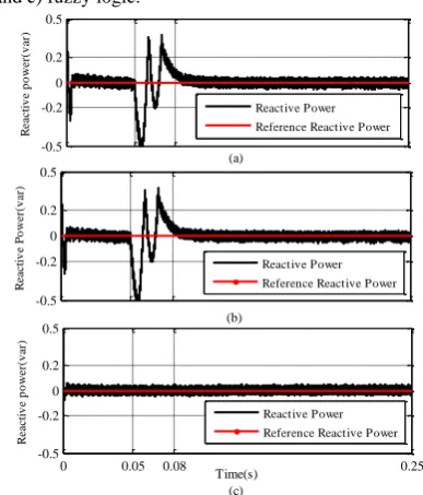
Fig. 6 shows reactive power by using the aforementioned three blocks. As observed, fuzzy estimator has lower ripple in comparison with the PI and optimized PI blocks. On the other hand, the reactive power response has a fast dynamic and low oscillations. Furthermore, no overshoots are observed.
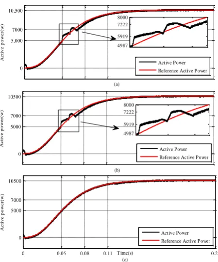
For the wind speed of 10 m/s, the generated power by the wind turbine is 10500 W which is considered as the reference value of DFIG. By estimating the rotor speed and applying the speed estimation methods, as shown in Fig. 7, active power tracks its reference value well and the fuzzy estimator has a satisfactory response.
Table 3 Specifications of Studied System Machine Parameters
Rated Voltage 220 V
Rated Power 20 kW
Rated Speed 1500 rpm
Pole Pairs 2
Stator Resistance 1.2 Ω Stator Inductance 0.1554 H Rotor Resistance 1.8 Ω Rotor Inductance 0.1558 H
HF signal and PI controller coefficients
High-frequency frequency 500 Hz High-frequency Voltage 9.5 V
0 50 200 257 300 S p ee d (r p m ) (a) 0 50 200 257 300 (b) S p ee d (r p m )
0 0.05 0.09 0.25
0 50 200 257 300 Time(s) (c) S p ee d (r p m ) Estimated speed Real speed Estimated speed Real speed Estimated speed Real speed
Fig. 5 Rotor speed and estimated speed by a) PI, b) optimized PI and c) fuzzy logic.
-0.5 -0.2 0 0.2 0.5 (a) R e a c ti v e p o w e r( v a r) -0.5 -0.2 0 0.2 0.5 (b) R e a c ti v e P o w e r( v a r)
0 0.05 0.08 0.25
-0.5 -0.2 0 0.2 0.5 Time(s) (c) R e a c ti v e p o w e r( v a r) Reactive Power Reference Reactive Power
Reactive Power Reference Reactive Power Reactive Power Reference Reactive Power
Fig. 6 Reference and Actual Reactive power achieved by a) PI, b) optimized PI and c) fuzzy logic controllers.
Iranian Journal of Electrical & Electronic Engineering, Vol. 14, No. 1, March 2018 17
The proper slip value for a DFIG is between -0.3 to 0.3. To evaluate the effects of speed variations on the power, the wind speed is increased from 10 m/s to 12 m/s. As shown in Fig. 8, the rotor speed is increased from 257 rpm to 310 rpm. This speed variation, as shown in Fig. 9(b), has little influence on the active and reactive powers when the fuzzy estimator is used. Quality and stability of the produced power in variable speed wind energy generation systems are of high importance. Fig. 10 depicts the stator voltages and currents, and the rotor currents. As observed, the stator and rotor currents have lower distortion when the proposed structure is used.
In order to evaluate the performance of the control system, the reference values of reactive and active power reference are changed. Fig. 11 illustrates active and reactive power tracking. As seen, by using the adaptive reference control and fuzzy system, the generator tracks the active and reactive powers with low ripple and satisfactory dynamic response.
0 5,000 7000 10,500 A c ti v e p o w e r( w ) (a) 0 5000 7000 10500 A c ti v e p o w e r( w ) (b)
0 0.05 0.08 0.11 0.25
0 5000 7000 10500 T ime(s) (c) A c ti v e p o w e r( w ) Active Power Reference Active Power
Active Power Reference Active Power
Active Power
Reference Active Power 4987 5919 7222 8000 4987 5919 7222 8000
Fig. 7 Reference and actual active power achieved by a) PI, b) optimized PI and c) fuzzy logic controllers.
0 0.05 0.1 0.25
0 105 200 310 350 T ime(s) S p ee d (r p m ) Estimated Speed Real Speed
Fig. 8 Increase of rotor speed due to increase in wind speed by using fuzzy logic estimator.
0 0.05 0.15 0.25
-1000 -500 0 500 1000 T ime(s) R e a c ti v e p o w e r( v a r)
0 0.067 0.135 0.25
0 14000 18000 20,000 T ime(s) (b) A c ti v e p o w e r( w )
0 0.05 0.15 0.25
-1000 -500 0 500 1000 T ime(s) R e a c ti v e p o w e r( v a r)
0 0.067 0.135 0.25
0 14000 18000 20,000 T ime(s) (a) A c ti v e p o w e r( w ) Reactive Power
Reference Reactive Power
Active Power
Reference Active Power Active Power
Reference Active Power
Reactive Power
Reference Reactive Power
0 0.05 0.15 0.25
-1000 -500 0 500 1000 T ime(s) R e a c ti v e p o w e r( v a r)
0 0.067 0.135 0.25
0 14000 18000 20,000 T ime(s) (b) A c ti v e p o w e r( w )
0 0.05 0.15 0.25
-1000 -500 0 500 1000 T ime(s) R e a c ti v e p o w e r( v a r)
0 0.067 0.135 0.25
0 14000 18000 20,000 T ime(s) (a) A c ti v e p o w e r( w ) Reactive Power Reference Reactive Power
Active Power
Reference Active Power Active Power
Reference Active Power
Reactive Power Reference Reactive Power
0 0.05 0.15 0.25
-1000 -500 0 500 1000 T ime(s) R e a c ti v e p o w e r( v a r)
0 0.067 0.135 0.25
0 14000 18000 20,000 T ime(s) (b) A c ti v e p o w e r( w )
0 0.05 0.15 0.25
-1000 -500 0 500 1000 T ime(s) R e a c ti v e p o w e r( v a r)
0 0.067 0.135 0.25
0 14000 18000 20,000 T ime(s) (a) A c ti v e p o w e r( w ) Reactive Power
Reference Reactive Power
Active Power
Reference Active Power Active Power
Reference Active Power
Reactive Power
Reference Reactive Power
0 0.05 0.15 0.25
-1000 -500 0 500 1000 T ime(s) R e a c ti v e p o w e r( v a r)
0 0.067 0.135 0.25
0 14000 18000 20,000 T ime(s) (b) A c ti v e p o w e r( w )
0 0.05 0.15 0.25
-1000 -500 0 500 1000 T ime(s) R e a c ti v e p o w e r( v a r)
0 0.067 0.135 0.25
0 14000 18000 20,000 T ime(s) (a) A c ti v e p o w e r( w ) Reactive Power Reference Reactive Power
Active Power
Reference Active Power Active Power
Reference Active Power
Reactive Power Reference Reactive Power
Fig. 9 Change of active and reactive power by a) PI and b) Fuzzy logic.
Iranian Journal of Electrical & Electronic Engineering, Vol. 14, No. 1, March 2018 18
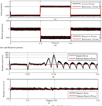
Due to the uncertainties of system such as the changes in the machine parameters or the wind speed, the system may be unstable. Therefore, a suitable control scheme is considered in the paper which results in appropriate output power control. As mentioned earlier, one of the advantages of fuzzy controllers in comparison with the PI controller is independency from the system parameters. Fig. 12 and Fig. 13 show the reactive and active power changes with 50 percent increase in the resistances for the PI and Fuzzy controllers, respectively.
As shown in Fig. 12(a) and Fig. 13(a), the system has oscillations at t = 0.12 and it also has the overshoot which increases the settling time. As a result, the system will remain in the unstable mode for a longer time. However, in Fig. 12(b) and Fig.13(b), with the same conditions, the system has a suitable dynamic response, has no overshoot and the settling time is decreased. All in all, considering to the simulation results, the advantages of the Fuzzy controller are verified.
5 Conclusion
In this paper, a DFIG-based wind energy generation system which uses an adaptive reference model to directly control the active and reactive powers is studied. The high-frequency signal injection method is used for speed estimation. In this method, PI, PI controller with optimized coefficients and fuzzy blocks are used in the speed control loop. The obtained results are compared. Simulation results demonstrate that the estimated speed perfectly matches the real speed. As a result, the reactive power has no overshoots and shows fast dynamic response and little oscillations in the steady state. It should be mentioned that the fuzzy controller is more robust against machine parameter changes than PI-controller and optimized PI-controller. This is a significant advantage of the proposed method over the two mentioned methods. Using the proposed fuzzy block, the active and reactive power references are tracked with lower ripple and faster dynamic response compared to PI and optimized-PI block.
-300 -163 0 163 300
(a)
V
s-ab
c
(V
)
-50 -20 0 20 50
(b)
is-ab
c
(A
)
0 0.03 0.12 0.2
-100 -60 0 60 100
T ime(s) (c)
ir
-a
b
c
(A
) 0
-5 0 5 0 -5
0 5
Fig. 10 a) stator voltages, b) stator currents and c) rotor currents.
Iranian Journal of Electrical & Electronic Engineering, Vol. 14, No. 1, March 2018 19 0
200 1000
(a)
A
ct
iv
e
po
w
er
(w
)
0 0.2 0.4
-400 0 400
T ime(s) (b)
R
ea
ct
iv
e
po
w
er
(v
ar
)
Act ive P ower
Reference P ower
React ive P ower
Reference P ower
Fig. 11 Active and Reactive powers.
Fig. 12 Sensitivity of reactive powers to the parameters variation. a) PI and b) Fuzzy logic.
Fig. 13 Sensitivity of active powers to the parameters variation. a) PI and b) Fuzzy logic
Iranian Journal of Electrical & Electronic Engineering, Vol. 14, No. 1, March 2018 20 References
[1] M. Tazil, V. Kumar, S. Kong, “Three-Phase doubly fed induction generator: An over view,” IET Electric Power Application, pp. 75–89, 2009. [2] H. Wanger, J. Mathur, Introduction to wind energy
systems. Green Energy and Technology, BerlinHeidelberg: Springer, 2013.
[3] M. T. Ackermann, Wind power in power system. Sweden: John Wiley & Sons, Ltd., 2005.
[4] E. Javan, A. Darabi, H. R. Ghafoori Gharib, and A. Emami, “Improved control of DFIG using stator-voltage oriented frame under unbalanced grid voltage conditions,” International Transactions on Electrical Energy Systems, Vol. 23, pp. 767–783, 2013.
[5] P. Vas, Sensorless vector and direct torque control (OCA). New Yourk: Oxford, 1998.
[6] M. Rizo, A. Rodriguez, E. Bueno and F. J. Rodriguez, “Robustness analysis of wind turbines based on PMSG with sensorless vector control,” IEEE Industrial Electronics Society, pp. 3103–3108, 2010.
[7] R. Cardenas, R. Pena, S. Alepzu and G. Asher, “Overview of control systems for the operation of DFIGs in wind energy applications,” IEEE Transactions on Industrial Electronics, Vol. 60, No. 7, pp. 2776–2798, 2013.
[8] R. Datta and V. T. Ranganathan, “A simple position sensorless algorithm for rotor side field-oriented control of wound-rotor induction machine,” IEEE Transactions on Industrial Electronics, Vol. 45, No. 4, pp. 786–793, 2001. [9] R. K. Patnaik, P. K. Dash, and K. Mahapatra,
“Adaptive terminal sliding mode power control of DFIG based wind energy conversion system for stability enhancement,” International Transactions on Electrical Energy Systems, Vol. 26, pp. 750– 782, 2016.
[10]F. Akel, T. Ghennam and M. laour, “An improvement sensorless decoupled power control scheme of grid connected variable speed wind turbine generator,” Energy Conversion and Management, pp. 584–594, 2013.
[11]I. Perez, J. Silva and R. Gonzalo, “Experimental sensorless vector control performance of a DFIG based on an extended kalman filter,” IEEE Power and Energy Society General Meeting, pp. 1–15, 2012.
[12]G. D. Marques and D. M. Sousa, “Air-gap-power-vector-based sensorless control in a DFIG connected to a dc link,” IEEE Transactions on Energy conversion, Vol. 30, No. 1, pp. 367–375, 2015.
[13]G. D. Marques, V. Pires and D. M. Sousa, “A DFIG sensorless rotor position detector based on a hysteresis controller,” IEEE Transaction on Energy Conversion, Vol. 26, No. 1, pp. 9–17, 2011.
[14]J. Sung Yu, C. Yuen Won, “performance of fuzzy logic based vector control for PMSM used in elevator drive,” The 30 annual conference of the IEEE industrial of electronics society, 2004. [15]D. D. Reigosa, F. Briz, C. B. Charro and
J. M. Guerrero, “Sensorless control of doubly fed induction generators based on rotor high-frequency signal injection,” IEEE Transactions on Industry Applications, Vol. 49, No. 6, pp. 2593–2601, 2013. [16]A. Fereidouni, M. A. Masoum and M. Moghbel, “A
new adaptive configuration of PID type fuzzy logic controller,” ISA Transactions, pp. 222–240. 2014. [17]M. Jazaeri, and A. A. Samadi, “Self-tuning fuzzy
PI-based controller of DFIG wind turbine for transient conditions enhancement,” International Transactions on Electrical Energy Systems, Vol. 25, pp. 2657–2673, 2015.
[18]C. B. Butt, M. A. Hoque, M. A. Rahman, “Simplified fuzzy-logic based MTPA speed control of IPMSM drive,” IEEE Transaction on application, Vol. 40, No. 6, pp. 1592–1535, 2004 [19]M. Ismail and F. Bendary, “Protection of DFIG
wind turbine using fuzzy logic control,” Alexandria Engineering Journal, pp. 941–949, 2016.
[20]G. Abed, J. Lopez and L. Marroyo, Doubly fed induction machines: Modeling and control for wind energy generation. Wiley 2011.
[21]K. Belmokhtar, M. L. Doumbia and K. Agbossou, “New sensorless fuzzy logic control strategy of wind energy conversion systems,” International symposium on power electronics, electrical drives, automation and mation. pp. 1–6. 2012.
[22]R. Cardenas, R. Pena, S. Alepuz, and G. Asher, “Overview of control system for the operation of DFIGs in wind energy applications,” IEEE Transactions on Industrial Electronics, Vol. 60, No. 7, pp. 2776–2798, 2013.
[23]F. Amrane and A. Chaiba, “Model reference adaptive control for DFIG based on DPC with a fix switching frequency,” IECEC, 2015.
[24]Y. D. Landau, Adaptive control: The model reference approach. Marcel ekker, New York, 1979.
[25]D. Reigosa, F. Briz, C. Blanco and J. M. Guerrero, “Sensorless control of doubly fed induction generators based on stator high frequency signal injection,” IEEE Transactions on Industry Applications, Vol. 49, No. 6, pp. 2593–2601, 2013. [26]D. Raca, F. Briz and R. D. Lorenz, “Carrier signal
selection for sensorless control of PM synchronous machines at very low and zero speeds,” IEEE Transactions on Industry Applications, Vol. 46, No. 1, pp. 167–178. 2010.
[27]A. H. Gandomi, A. H. Alavi, “Krill Herd: A New
Bioinspired Optimization Algorithm,”
Communications in Nonlinear Science and Numerical Simulation, Vol. 17, No. 12, pp. 4831– 4845, 2012.
Iranian Journal of Electrical & Electronic Engineering, Vol. 14, No. 1, March 2018 21
[28]S. Rajana, S. Sahadev, “Performance Improvement of fuzzy logic controller using neural network,” International Conference on Emerging Trends in Engineering, Science and Technology, pp. 704– 714. 2015.
R. Pourebrahim received the B.Sc. degree in electrical engineering from the University of Tabriz, Iran, in 2013, and the M.Sc. degree in Electrical Engineering from the University of Tabriz, Tabriz, Iran, in 2016.
She is currently pursuing the Ph.D. degree with the Department of Electrical and Computer Engineering, University of Tabriz, Tabriz, Iran.
Her current research interests include wind power technology, control of wind energy conversion systems, and energy storage systems.
S. Tohidi was born in Meshkin Shahr, Iran, in 1984. He received the B.Sc. degree from Iran, University of Science and Technology, Tehran, Iran, in 2006, and M.Sc. degree from Sharif University of Technology, Tehran, Iran, in 2008, both in Electrical Engineering.
He is currently an Assistant Professor at University of Tabriz, Iran. He was on sabbatical at Durham University, Durham, U.K., and University of Cambridge, Cambridge, U.K., in 2011. His research interests include power systems dynamics, electrical machines, and wind power generation.
A. Younesi received the B.Sc. degree in electrical engineering from the University of Mohaghegh Ardabili, Ardabil, Iran, in
2013, and the M.Sc. degree in Electrical Engineering from the University of Tabriz, Tabriz, Iran, in 2015.
He is currently pursuing the Ph.D. degree with the Department of Electrical and Computer Engineering, University of Tabriz, Tabriz, Iran.
His research interests include electrical machine and drives, model predictive control, control of wind turbine generators.
![Fig. 1 d-q synchronous reference frame on the stator flux [20].](https://thumb-us.123doks.com/thumbv2/123dok_us/24913.2002748/3.595.109.231.643.742/fig-d-q-synchronous-reference-frame-stator-flux.webp)
![Fig. 3 Simplified flowchart of KH algorithm [28].](https://thumb-us.123doks.com/thumbv2/123dok_us/24913.2002748/5.595.79.274.362.748/fig-simplified-flowchart-kh-algorithm.webp)