Iranian Journal of Electrical and Electronic Engineering, Vol. 16, No. 1, March 2020 66
Implementation of Identical Spiral Square Inductive Coils for
Wireless EV Battery Charging Application
D. Kishan*(C.A.), P. S. R. Nayak** and B. Naresh Kumar Reddy*
Abstract: In recent years, the popularity of wireless inductive power transfer (WIPT) system for electric vehicle battery charging (EVBC) is always ever-increasing. In the WIPT inductively coupled coil structure is the heart of the system and the mutual inductance (MI) between the coupled coils is the key factor for effective power transfer. This paper presents the analysis of mutual inductance between the spiral square coils based on the cross-sectional area ratio of spiral circular and spiral square coupled coils. The analytical computed MI values are compared with FEM (ANSYS Maxwell) simulation and Experimental computed values. Finally, the designed spiral square coils are implemented in a laboratory prototype model and at the receiver side for effective electric vehicle (EV) battery charging a closed-loop PID controller is implemented for DC-DC buck converter. The effectiveness of the proposed controller has been tested by providing sudden changes in mutual coupling and change in reference value. The proposed system is suitable for both stationary and dynamic wireless EVBC.
Keywords: Inductive Power Transfer, Battery, Electric Vehicle, Mutual Inductance.
1 Introduction1
HE fossil fuel vehicles are causing 34% of the air pollution, which brings about expanding global warming [1]. So as to lessen this issue to some extent, it is important to confine the utilization of fossil fuels. Researchers are addressed the electrification of vehicles (EV) to overcome the pollution problem. The main advantages of electrified vehicles are operated smoothly and emission-free [2, 3]. These vehicles are operated on battery rather than fuel. Hence, electric vehicles are used heavily in marker to reduce pollution. One such significant apprehension of EV’s is the conductive battery charging (in) applications [1, 2]. The plug-in or conductive battery chargplug-ing requires vast
Iranian Journal of Electrical and Electronic Engineering, 2020. Paper first received 22 May 2019, revised 01 September 2019, and accepted 03 September 2019.
* The authors are with the Department of Electrical and Electronics Engineering, Faculty of Science and Technology, ICFAI Foundation for Higher Education (IFHE) – Hyderabad, Telangana, India. E-mails: [email protected] and [email protected]. ** The author is with the Department of Electrical and Electronics Engineering, National Institute of Technology Tiruchirappalli, India. E-mail: [email protected].
Corresponding Author: D. Kishan.
establishment of charge stations, charging plug and cable can be easily damaged, stolen and sometimes user forget to plug the electric vehicle. The issues related to conductive charging can be overwhelmed by wireless charging. Wireless power can be transferred through the air. Therefore wireless electric vehicle battery charging is to simplify the consumer anxieties and speed up EV adoption [2, 3]. In wireless power transfer system, the coil associated with the source is termed as a transmitter and the coil at the load side is known as a receiver [4]. In WPT system, the power can be transferred in the form of electromagnetic energy or electrostatic energy or radiative energy. In high power rating and medium distance system, power can be transferred more likely through electromagnetic energy, which is called inductive power transfer system (IPTS). The functionality of IPTS is conventional transformer, which is based on Ampere’s and Faraday’s law. The most important part of the IPT system is the coupled coil structure which forms the wireless link. The extensive literature has been studied and published over time. The conventional coil structures design employs E-cores and pot cores [4, 5]. However, these core structures are incompatible for electric vehicle battery charging applications. Moreover, these core designs are weighty, sensitive to horizontal
T
Iranian Journal of Electrical and Electronic Engineering, Vol. 16, No. 1, March 2020 67 misalignments and also expensive [6, 7]. To overcome
the problems associated with conventional design, various planar coil designs that are having more tolerant to misalignment are widely deployed for stationary charging of electric vehicles and these coils are into two categories as polarized pads and non-polarized pads [2, 3, 5]. The polarized pads are multiple coil pads that can couple and create the parallel, perpendicular or both the component of flux and these pads are having H-shaped ferrite bar with double side winding [6, 8]. However, these pads also generate flux out the back of the pad, therefore when an aluminum backing plate is added it generates more loss, in the form of eddy current than that usually expected for an EV charging system. To overcome the aforesaid limitations of the H-shaped coil, single-sided pads were developed. The non-polarized pads are single coil pads which can generate only perpendicular flux. The spiral circular and spiral square coils are the most commonly used since these are nonpolarized coils. These coils have the tolerance to misalignment in all directions, easier to operate. They are nondirectional, i.e. a vehicle can approach them from any direction. Hence, spiral square coils are adopted in this work.
In WIPT system the power can be transferred when the magnetic fields generated by the transmitter coil are picked up by the receiver coil, due to limits of the misalignment and vertical distance between the coils mutual inductance deficiency will occur. The varied air gap and horizontal misalignment lead to varied coupling i.e., varied mutual inductance (MI) between the coils. Thus, the electrical characteristics of the overall IPT system can be seriously changed. [7, 8]. Hence, computation of MI is the key factor. Recently few methods are reported for computing MI [9-12]. These methods require complex computations and are also less accurate due to parameter sensitivity. The Neumann’s equation-based MI computation for spiral circular coils at different misalignments is presented [10] and it is considered in this work for spiral square coils based on the ratio of areas of the spiral circular and square coils. In WIPT system to reduce the VA rating (ratio of maximum source apparent power to load nominal power) and improve the power transfer capability of the system, capacitor compensation is essential. Since last decade tremendous research work has been presented in literature [11-13]. Further, [13] and [14], have described the conventional four compensation topologies other than dual side LC [13] compensation topologies. Among all compensation techniques, series/series (S/S) compensation is simple to design and economical hence S/S compensation topology is adopted [11, 12].
The controllers involved in the WIPT system should be adaptive, comprehensive, and easy to provide stable and efficient charging power to the load, even when the coupling effect is changed. Constant and variable frequency control methods are major control techniques for inverter of the transmitter coil. In constant frequency
control method, the inverter switches are forced drive at predetermined value of switching frequency, hence it does not vary with any changes in the WIPT circuit parameters [15, 16]. In this type of control method, the operating frequency is constant and system will be stable frequency point of view. In the variable frequency control method, the frequency variation is allowed within its specific limit of range to follow the resonance [17, 18]. The disadvantage associated with this method is the operating frequency will affect the load changes and parameter variations. In this work, constant frequency and constant duty cycle control method is employed for high-frequency full-bridge inverter and at the receiver side DC-DC buck converter is employed to control the battery charging voltage regulation by using feedback closed-loop PID controller.
The organization of the paper is as follows, Section 2 describes the modeling of SS resonant WIPT system and analytical modeling of the spiral square coils. Section 3 investigates the MI between the spiral square coils at different misalignment conditions. Section 4, the implementation results of the WIPT system for battery charging application and the efficiency, charging current analysis at different misalignments is clearly presented. Finally, Section 5 concluded the paper.
2 Analytical Modelling of the WIPT System
2.1 Modeling of SS Resonant WIPT System
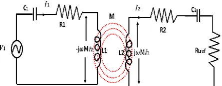
The equivalent circuit model of the series-series resonant wireless inductive power transfer system is shown in Fig. 2. The transmitter side of the SS-RWIPT is fed by the high-frequency AC voltage (V1) from
output of the full-bridge inverter. On the receiver side, a high frequency induced voltage is converted into pulsed DC voltage using diode bridge rectifier and it is filtered using a capacitor (Cf). The SS compensated capacitor of
the resonant WIPT system is given below.
1 2 2 2
0 1 0 2
1 1
,
C C
L L
(1)
The schematic equivalent circuit of S/S compensated resonant WIPT system is shown in Fig. 1. The maximum power transfer efficiency (PTE) and inductive coupled coil impedances can be calculated by using the following equations.
Fig. 1 Equivalent circuit model of SS resonant IPT system.
Iranian Journal of Electrical and Electronic Engineering, Vol. 16, No. 1, March 2020 68 1 1 1 1 1 Z C
j L R
j (2) 2 2 2 2 1 Z C
j L R
j (3) 1 2 1 2 2 1 ( ) ( )( ) ( ) L L S
V Z R I
Z R Z R M
(4)
1
2 2
2 1
( )
( L)( S) ( )
V M I
Z R Z R M
(5)
At the condition of resonance, the overall reactance of the coupled coils will become zero. The output and input power are as follows
2 1
2
2 1
( )
( L)( S) ( ) L
outpu
V M
R Z R Z R M
P
(6)
2 1 2 1 2 2 1 2 1 2 2 2 1 ( ) ( )( ) ( ) ( ) ( ) ( )( ) ( ) L L S L L S input
V Z R
R
Z R Z R M
V M
R R
Z R Z R M
P
(7)
2 2 1 2 2 2 2 ( ) ( )( ) LL s L
R
R R R R R R M M
(8)
2.2 Analytical Modeling of Spiral Square Coil
A modified Wheeler formula can be used for calculations of self inductance of planar spiral square inductive coils and it is presented in (9) [8].
2
2
2 2.067
ln 0.17 0.125
sq
N P
L Q Q
Q
(9)
where N = number of turns and mean radius of the
0.5(out in) coil
P r r ,
( ) ( ) out in out in r r Q r r .
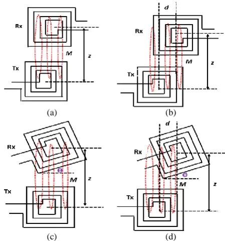
2.3 Misalignments of the Spiral Square Coils
This subsection provides possible alignments of the inductive couple coils. These alignments may occur in real-time applications due to the unequal surface of the
Fig. 2 Representation of a spiral square coil.
transportation roads. All these alignments are used for computing mutual inductance, charging current and overall efficiency of the WIPT system.
3 Investigation of Mutual Inductance between Spiral Square Coupled Coils
3.1 Analytical Computation of MI
The misalignments of the spiral square coils, the same as spiral circular are given following sections and also the analytical calculations are carried out for the as mentioned misalignments of the circular coils only. The area of the square coil with the same diameter of the spiral circular coil is 4/π times higher. Thus the MI between the planar spiral square coil can be calculated using (10). The computation of MI for identical spiral circular coils is adopted from [10] and also presented in the appendix.
2
4
( ) ( )
ij ij
M square M cir
(10)
3.2 Computation of MI through FEM Modelling
A 3-D FEM modeling tool ANSYS Maxwell 14.0.0 has been used for validating the analytical computed MI between the spiral square coupled coils. The spiral square coil setups developed in the FEM simulation at different misalignments are shown in Fig. 4.
Fig. 5, depicts the magnetic field distribution between the spiral square inductively coupled coils at 100mm distance at perfect alignments condition. Fig. 5(a) provides magnetic field distribution between the spiral square coupled coils without a core. Similarly
(a) (b)
(c) (d)
Fig. 3 Possible alignment of spiral square WIPT coils; a) Perfect alignment, b) Lateral misalignment, c) Angular
misalignment, and d) Planar and angular misalignment.
Iranian Journal of Electrical and Electronic Engineering, Vol. 16, No. 1, March 2020 69
(a) (b) (c) (d)
Fig. 4 Spiral square coil arrangement in FEM simulation; a) Perfect alignment, b) Lateral misalignment, c) Angular misalignment,
and d) Planar and angular misalignment.
(a) (b) (c)
Fig. 5 Magnetic field distribution between the coupled coils at 100mm vertical distance; a) Perfect alignment, b) Lateral misalignment (40mm), and c) Angular misalignment (30°).
(a) (b) (c) (d)
Fig. 6 Alignments of square coupled coils in the laboratory; a) Perfect alignment, b) Lateral misalignment, c) Angular misalignment, and d) Planar and angular misalignment.
Figs. 5(b), and 5(c) show at planar and angular misalignments, respectively. It observed that the magnetic flux density is more in case of perfect alignment compared to the planar and angular misalignments.
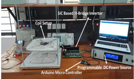
3.3 Validation of MI through Experimentation
The experimental prototype model developed in the laboratory is shown in Fig. 7. The developed setup consists of spiral square coils, Arduino microcontroller, and MOSFET H-bridge inverter. The spiral square coils are made up of 0.1mm/1500 strands Litz wire and manually created misalignments of the spiral square inductive coils are shown in Fig. 6. The receiver coil open-circuit voltage has been measured and the MI is computed using (11).
2
1
oc
V MI
I
(11)
3.4 Comparative Analysis of MI
The analytical computed MI are compared with FEM
Fig. 7 Experimental MI investigating setup for spiral square coils.
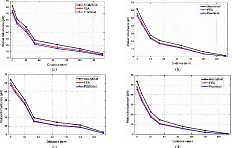
simulation results and experimental computed values. Fig. 8. shows the variation of mutual inductance at different alignments with different vertical distance between the inductive coupled coils and all these misalignments are created in simulation and experimentations. As, the distance between the coupled coils increases the mutual coupling decreases, which results in the reduction of MI and also as misalignment
Iranian Journal of Electrical and Electronic Engineering, Vol. 16, No. 1, March 2020 70
(a) (b)
(c) (d)
Fig. 8 MI Vs Distance for spiral square coil structure at a) perfect alignment, b) lateral misalignment (40mm), c) angular misalignment (30°), and d) planar and angular misalignment (40mm & 15°).
distance increases which also effects the MI. The MI at manually created alignments such as perfect alignment, planar misalignment (40mm), angular misalignment (30°) and planar and angular misalignments (40mm & 15°) are presented in Figs. 8(a), (b), (c), and (d), respectively.
4 Implementation Spiral Square coils for WIPT
The developed spiral square coupled coils are implemented in a laboratory prototype. The efficient charging of EV battery requires either constant voltage or constant current supply mode. In this regard, the receiver coil generates high-frequency voltage and when it is connected to the load, the current starts flowing to load. The high-frequency AC power converts into a DC power using a full bridge diode rectifier. The out of the diode bridge rectifier is pulsating DC. In order to obtain pure DC filter capacitor is used. For efficient battery charging, depending on the voltage specification of the battery, the DC-DC converter can be selected. In this work, DC-DC buck converter is chosen. The closed-loop modeling steps of the DC-DC buck converter is presented in [19]. The transfer function of the non-ideal buck converter is given by (12) [19].
0
2 0
7879.92 2984414390.3
( )
( ) 658.3512 2995313.126.3
s
v s
d s s s
(12)
Using the open-loop transfer function derived [19], the step response and frequency response of the buck converter can be obtained. Through step response, the dynamic performance of the system can be evaluated and stability analysis can be done through frequency response. Using the Bode plot method, Gain margin (GM) and Phase margin (PM) can be determined and these two values bound the behavior of the closed-loop system [19]. The obtained PID controller gain values are KP=0.12, KI=11.32, and KD=18 and the following case studies were performed for testing the designed controller.
Case I: Change in reference voltage at the fixed load. Case II: Change in mutual coupling at a fixed load. All the case studies have been performed for load resistance (8Ω) for the CV charging mode and the input power is supplied from a DC constant source 600W.
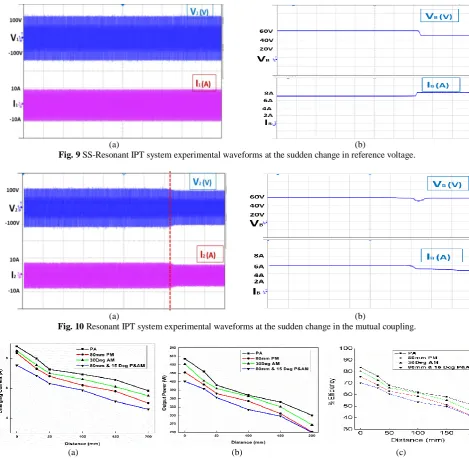
Case I: Change in reference voltage at the fixed load To test the robustness of the designed controller, the battery reference voltage has been stepped down from 60V to 50V at a fixed load resistance RLof value 8Ω.
Fig. 9 shows the transient performance of experimental results. From the results, it is clear that no transient occurs due to the appropriate controller design.
Case II: Change in mutual coupling at a fixed load To check the performance of the controller at variation of alignment between the coupled coils,
Iranian Journal of Electrical and Electronic Engineering, Vol. 16, No. 1, March 2020 71
(a) (b)
Fig. 9 SS-Resonant IPT system experimental waveforms at the sudden change in reference voltage.
(a) (b)
Fig. 10 Resonant IPT system experimental waveforms at the sudden change in the mutual coupling.
(a) (b) (c)
Fig. 11 Measured results at different misalignments and different vertical distances; a) Battery charging current, b) Output power, and c) Overall system efficiency.
transmitter and receiver, planar misalignment of the receiver with respect to transmitter was manually created (40mm). the battery reference voltage was kept at fixed 60V. the results observed are shown in Fig. 10. The output battery charging voltage is maintained at constant 60 volts. The current and power analysis of the SSRIPT system is shown in Figs. 11(a) and 11(b), respectively. It is observed that at zero misalignments (at perfect alignment) the charging current is higher while misalignment distance increases the charging current decreases which results in higher in charging time.
The overall system efficiency (input DC to output DC) is measured at various alignments of the coupled coils and it depicted in Fig. 11(c). It is clear that as the distance between the coupled coils increases, the overall
efficiency of the system decreases i.e., the losses in the system increases. However, the experimental setup developed was for proof of concept, hence the achieved efficiency is relatively low. The overall efficiency of the system further can be improved by increasing the power rating and providing proper cooling to the system.
5 Conclusion
This paper investigates the computation of mutual inductance between the spiral square coils based on the cross-sectional area ratio of spiral circular and spiral square of the coupled coils. The analytical computed MI values are compared with FEM (ANSYS Maxwell) simulation and Experimental computed values. The designed spiral square coupled coils are used for
Iranian Journal of Electrical and Electronic Engineering, Vol. 16, No. 1, March 2020 72 validating WIPT system in laboratory model. At the
receiver side of the WIPT system for effective electric vehicle (EV) battery charging a closed-loop PID controller has been implemented for DC-DC buck converter. The effectiveness of the proposed controller has been tested by providing sudden changes in load, mutual coupling and change in reference value. The proposed system is suitable for both stationary and dynamic wireless charging of electric vehicles.
Appendix
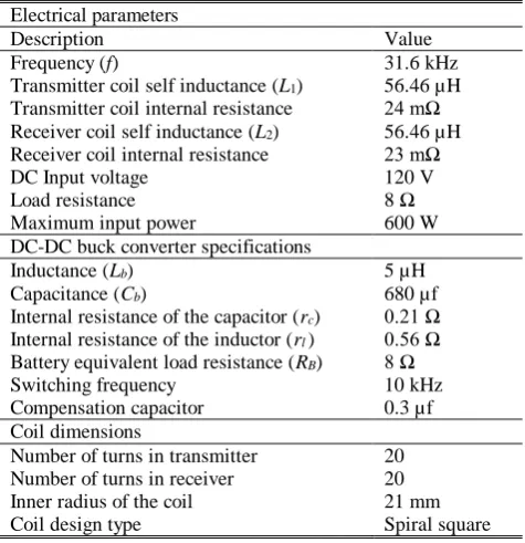
Table 1 Specifications of the WIPT System.
Electrical parameters
Description Value
Frequency (f) 31.6 kHz
Transmitter coil self inductance (L1) 56.46 µH Transmitter coil internal resistance 24 mΩ Receiver coil self inductance (L2) 56.46 µH Receiver coil internal resistance 23 mΩ
DC Input voltage 120 V
Load resistance 8 Ω
Maximum input power 600 W
DC-DC buck converter specifications
Inductance (Lb) 5 µH
Capacitance (Cb) 680 µf
Internal resistance of the capacitor (rc) 0.21 Ω
Internal resistance of the inductor (rl) 0.56 Ω
Battery equivalent load resistance (RB) 8 Ω
Switching frequency 10 kHz
Compensation capacitor 0.3 µf
Coil dimensions
Number of turns in transmitter 20
Number of turns in receiver 20
Inner radius of the coil 21 mm
Coil design type Spiral square
References
[1] A. Khaligh and S. Dusmez “Comprehensive topological analysis of conductive and inductive charging solutions for plug-in electric vehicles,”
IEEE Transactions Vehicular Technology, Vol. 61, No. 8, pp. 3475–3489, 2012.
[2] S. Li and C. Mi, “Wireless power transfer for electric vehicle applications,” IEEE Journal on Emerging and Selected Topics in Power Electronics, Vol. 3, No. 1, pp. 4–17, 2015.
[3] G. A. Covic and J. T. Boys, “Modern trends in inductive power transfer for transportation applications,” IEEE Journal of. Emerging Selected Topics in Power Electronics, Vol. 1, No. 1, pp. 28– 41, 2013.
[4] F. Musavi and W. Eberle, “Overview of wireless power transfer technologies for electric vehicle battery charging,” IET Power Electronics, Vol. 7, No. 1, pp. 60–66, 2014.
[5] D. Kishan, P S Nayak, “Wireless power transfer technologies for electric vehicle battery charging – A state of the art,” in Proceedings of IEEE International Conference on Signal Processing, Communication, Power and Embedded System (SCOPES), pp. 2069–2073, Oct. 2016.
[6] A. A. S. Mohamed, A. A. Marim, and O. A. Mohammed, “Magnetic design considerations of bidirectional inductive wireless power transfer system for EV applications,” IEEE Transactions on Magnetics, Vol. 53, No. 6, pp. 1–8, 2017.
[7] L. Huang, G. Meunier, and O. Chadebec, “General integral formulation of magnetic flux computation and its application to inductive power transfer system,” IEEE Transactions on Magnetics, Vol. 53, No. 6, pp. 14–21, 2017.
[8] Y. Cheng and Y. Shu, “A new analytical calculation of the mutual inductance of the coaxial spiral rectangular coils,” IEEE Transactions on Magnetics, Vol. 50, No. 4, pp. 1–6, 2014.
[9] S. I. Babic, F. Sirois, and C. Akeyl, “Validity check of mutual inductance for circular filaments with lateral and planar misalignment,” Progress In Electromagnetic Research, Vol. 8, pp. 15–26, 2009. [10]P S. R. Nayak, D. Kishan, and P. Sathish, “Investigation of MI between circular spiral coils with misalignments for electric vehicle battery charging,” IET Science, Measurement & Technology, Vol. 12, No. 8, pp. 844–850, 2018. [11]W. Li, H. Zhao, J. Deng, S. Li, and C. C. Mi.
“Comparison study on SS and double-sided LCC compensation topologies for EV/PHEV wireless chargers,” IEEE Transactions on Vehicular Technology, Vol. 65, No. 6, pp. 4429–4439, 2016. [12]W. Zhang, S. C.Wong, K. T. Chi, and Q. Chen,
“Analysis and comparison of secondary series- and parallel-compensated inductive power transfer systems operating for optimal efficiency and load-independent voltage-transfer ratio,” IEEE Transactions on Power Electronics, Vol. 29, No. 6, pp. 2979–2990, 2014.
[13]C. Liu, S. K. Ge, Y. Guo, H. Li, and G. W. Cai, “Double-LCL resonant compensation network for electric vehicles wireless power transfer: experimental study and analysis,” IET Power Electronics, Vol. 9, No. 11, pp. 2262–2270, 2016. [14]X. Qu, Y. Jing, H. Han, S. C. Wong, and K. T. Chi,
“Higher order compensation for inductive-power-transfer converters with constant-voltage or constant-current output combating transformer parameter constraints,” IEEE Transactions on Power Electronics, Vol. 32, No. 1, pp. 394–405, 2017.
Iranian Journal of Electrical and Electronic Engineering, Vol. 16, No. 1, March 2020 73 [15]A. Berger, M. Agostinelli, S. Vesti, J. A. Oliver,
J. A. Cobos, and M. Huemer, “A wireless charging system applying phase-shift and amplitude control to maximize efficiency and extractable power,” IEEE Transactions on Power Electronics, Vol. 30, No. 11, pp. 6338–6348, 2015.
[16]J. Hou, Q. Chen, S. C. Wong, K. T. Chi, and X. Ruan, “Analysis and control of series/series-parallel compensated resonant converters for contactless power transfer,” IEEE Journal of Emerging and Selected Topics in Power Electronics, Vol. 3, No. 1, pp. 124–136, 2015.
[17]W. Zhang, S. C. Wong, K. T. Chi, and Q. Chen, “Design for efficiency optimization and voltage controllability of series-series compensated inductive power transfer systems,” IEEE Transactions on Power Electronics, Vol. 29, No. 1, pp. 191–200, 2013.
[18]T. Diekhans and R. W. De Doncker, “A dual-side controlled inductive power transfer system optimized for large coupling factor variations and partial load,” IEEE Transactions on Power Electronics, Vol. 30, No. 11, pp. 6320–6328, 2015. [19]K. Sundareswaran, V. Devi, S. Sankar,
P. S. R. Nayak, and S. Peddapati “Feedback controller design for a boost converter through evolutionary algorithms,” IET Power Electronics, Vol. 7, No. 4, pp. 903–913, 2014.
D. Kishan received the bachelor of
engineering degree in Electrical and Electronics Engineering in 2011, masters of technology degree in 2013, India, and Ph.D., in 2018. He is currently an Assistant Professor in the Department of Electrical and Electronics Engineering, Faculty of Science and Technology, ICFAI Foundation for Higher Education (IFHE) – Hyderabad, Telangana, India. His research interests focus on wireless power transfer for electric vehicle battery charging, power electronics applications in electric vehicles.
P. S. R. Nayak was born in Guntur, India, in 1979. He received the B.Tech. degree in Electrical and Electronics Engineering from Bapatla Engineering College, Guntur, in 2001, the M.Tech. degree in Energy Systems from Jawaharlal Nehru Technological University, Hyderabad, India, in 2006, and the Ph.D. degree in Electrical Engineering from the National Institute of Technology, Tiruchirappalli, India, in 2014. He is currently an Assistant Professor in the Department of Electrical and Electronics Engineering, National Institute of Technology, Tiruchirappalli. His research interests include power electronics and drives, and biologically inspired optimization techniques.
B. Naresh Kumar Reddy received the
bachelor of engineering degree in Electronics and Communication in 2010, masters of engineering degree in 2012, India, and Ph.D., in 2018. He is currently an Assistant Professor in the Department of Electrical and Electronics Engineering, Faculty of Science and Technology, ICFAI Foundation for Higher Education (IFHE) – Hyderabad, Telangana, India. His research interests focus on embedded systems, on-chip multiprocessors, reconfigurable systems. He is co-author of several scientific papers on networks-on-chip, design methodologies for systems-on-chip, embedded systems.
© 2020 by the authors. Licensee IUST, Tehran, Iran. This article is an open access article distributed under the terms and conditions of the Creative Commons Attribution-NonCommercial 4.0 International (CC BY-NC 4.0) license (https://creativecommons.org/licenses/by-nc/4.0/).