20th International Conference on Structural Mechanics in Reactor Technology (SMiRT 20) Espoo, Finland, August 9-14, 2009 SMiRT 20-Division 6, Paper 1937
Improving Constructability of the New Generation Nuclear Construction
Javeed Munshi, Ph.D., S.E., P.E.
a aPrincipal Engineer, Bechtel Power Corporation, Fredrick, USA, e-mail: [email protected]
Keywords: constructability, higher grade reinforcement, reinforcement congestion, high-performance concrete, rebar modeling.
1
ABSTRACT
Preliminary indications are that new generation nuclear structures will need significant amount of reinforcement in order to make them conform to the current regulatory requirements, Codes and Standards. The concern is that amount of reinforcement required is likely to cause congestion and consequent concrete placement problems thus impacting constructability of new generation nuclear plant structures. This paper discusses the various causes that contribute to this situation. Several practical ways to mitigate this situation are discussed which include improving the analysis and design process to remove some of the conservatism, use of higher grade reinforcement, use of headed bars and mechanical splices instead of lap splices, modelling of rebar and embeds to head off potential interferences and last but not the least, use of a high-performance mix that improves ease of placement and consolidation.
2
INTRODUCTION
Figure 1 shows the reinforcement of various components of the USEPR project based on preliminary design. The factors that contribute to the current reinforcement requirements include:
1. The revised seismic hazard criteria/ground motion data resulting in higher design forces.
2. Standard plant concept which requires that a standard plant be designed for a suite of soil conditions ranging from very poor soil to rock site.
3. 2-Step Method of Analysis which involves using the envelop of seismic forces (irrespective of the fact that they may occur at different times) from the soil structure interaction model analysis as static input to structural analysis model for design of concrete elements.
4. Interpretation of finite element results – because of lack of a rational methodology, the following process is currently adopted for design of concrete walls.
i. The design is based on envelop of element forces which may occur at different times during the analysis.
ii. The out-of-plane bending is assumed to occur simultaneously with the in-plane forces. Note that out-of-plane bending of wall is generally a high frequency mode and does occur simultaneously with in-plane shear.
iii. A sectional methodology is applied to design elements in the vertical and horizontal direction which are assumed to act independently as columns.
The design loads combined with many layers of conservatism discussed above add to the required reinforcement and potential congestion.
3
IMPROVING CONSTRUCTABILITY
This paper recommends the following practical ways of improving constructability which could be pursued simultaneously.
3.1
Improving Analysis and Design Process
As indicated in Section 2 above, most of the conservatism is as a result of the so called “2-Step” analysis and design method which introduces multiple layers of conservatism into the design. The idea here would be to peel off some of this unnecessary conservatism through an improved analysis and design process. Ref. 1 (2009) discusses this issue in detail by evaluating various design methodologies currently used in the industry. The incompatibility of using the FEM analysis results with design approaches prescribed in the Codes/Standards is discussed. Based on this discussion, a rational and transparent analysis/design approach aimed at reducing the overall conservatism is outlined.
3.2 Use of Higher Grade Reinforcement
For the same design forces, substituting higher Grade reinforcement for conventional Gr 60 rebar reduces the amount of reinforcement and allows larger spacing between bars. This has a direct impact on reducing rebar congestion. Note that Grade 75 reinforcement is permitted in ACI 318 under ASTM A615 and has been in use for over 20 years now. However, it is not currently allowed by NRC and not recognized in ACI 349 and ASME Div 2, Section III (ACI 359) Codes. In order to use higher grade reinforcement in the US nuclear industry, Code change proposals are being proposed in ACI 349 and ACI 359 (ASME) Codes. Note that both these Codes are due for revision in 2010. In order to pursue this issue, a case is made herein for use of Gr 75 reinforcement which is becoming a topic of general industry interest.
The chemistry control and bend requirements of Grades 60 and 75 are essentially the same. The elongation requirement, which is used as a measure of ductility, is 7% for Grade 60 and 6% for Grade 75 for No. 9 and larger bars. Note that No. 9 and larger size bars are predominantly used in nuclear construction. A review of all the available test data on Gr 75 reinforcement indicated an average elongation in excess of 12%.
ASTM A615 Grade 60 reinforcement has been successfully used in nuclear and defense construction to resist both seismic as well as impact loads. Since nuclear structures are designed to remain essentially elastic during a design seismic event, a marginal reduction in elongation requirement [from 7% to 6% elongation] should not be an issue for use of Grade 75 reinforcement. For impact type of loads, the expected ductility of concrete elements with Grade 60 reinforcement is given in Appendix F of ACI 349. Although this appendix calls for use of A706 reinforcement, the allowable ductility values are still based on ASTM A615 reinforcement used previously and as such Gr 75 reinforcement will meet these requirements for impact loading. Furthermore, tests have shown that there is no adverse impact on ductility of Gr 75 reinforcement as a result of strain rate effect and that ultimate strain limits established under static loads remain valid.
3.2.1 Current Codes
Regarding impulsive and impactive loads, ASTM A706 [4] reinforcement was introduced in Appendix C of ACI 349-01 for the first time. But the allowable ductility values were not updated as a result of this change from A615 to A706 steel. This is apparent from Reg. Guides 1.142 (1981 and 2001). These documents reference ASTM A615 and have the same recommendations for the allowable ductility values. Note that 1981 Reg Guide references ACI 349-76 while 2001 version references ACI 349-97. In other words 2001 edition of Reg Guide 1.142 does not recognize ASTM A706 and recommends ductility values that are consistent with ASTM A615 reinforcement. Since it seems that A706 rebar was introduced in 2001 ver of ACI 349, the ductility values specified in 2001 Reg guide, based on ACI 349-76 and -97, assuming A615 rebar still remain in effect.
ACI 349 closely follows the developments in ACI 318 and as such has to be periodically updated. However, the update of the Code in 2006 for changes in 2005 edition of ACI 318 Building Code [6] resulted in some discrepancies. ACI 318-05 allows Grade 75 reinforcement as permitted under ASTM A615. This change was picked up by ACI 349-06 in Section 3.5.3.2. But Section 9.4 of ACI 349-06, unlike that of ACI 318-05, maintained the limit on the yield strength of reinforcement to 60,000 psi. Commentary Section R9.4 of both ACI 318-05 and 349-06 indicate that this limit applies to transverse reinforcement because of seismic issues and references Section 21.2.5. Somehow after chasing these sections down, it is not clear if Grade 75 is permitted in ACI 349-06. Section 3.5.3.2 along with R9.4 and 21.2.5 of ACI 349-06 seem to suggest that it is permitted while Section 9.4 explicitly limits the yield strength of reinforcement to 60,000 psi. It seems that this discrepancy may have been caused inadvertently as some sections were updated for ACI 318-05 while others were left unchanged. The result is that ACI 349-06 is neither consistent within itself as it permits Grade 75 in section 3.5.3.2 and does not in Section 9.4 nor with ACI 318 which serves as the source document for most of its material, design and detailing related provisions.
3.2.2 Gr 75 Reinforcement- History Of Use And Performance
Grade 75 was first introduced in ASTM A615-87a (in 1987) and has been in use for over 20 years now. ACI 318 first introduced Grade 75 rebar in 1989 edition of the Code without much hesitation or reservation as it conformed to the same specifications as Grade 60 reinforcement under ASTM A615. The primary application of Grade 75 was in high strength concrete columns of medium to high-rise buildings and in foundation mats to relieve congestion of reinforcement. Bechtel has used it in various applications including foundation mats of fossil power structures where design was controlled by strength requirements and/or to relieve rebar congestion.
Note that Section 5.4.3.1 of 2007 AASHTO LRFD Bridge Design Specification [7] also allows Gr 75 reinforcement for bridge construction.
As indicated above, Gr 75 reinforcement has been in use for over 20 years now. So far no performance issues have been reported with structural systems using this reinforcement. All the tests [8 - 11] conducted on higher grade reinforcement so far have all indicated that performance is similar to that of conventional Gr. 60 steel and no significant changes are necessary to adjust the design parameters such as bond, ductility etc.
Ductility of Gr 60 vs Gr 75. Grade 75 reinforcement like Grade 60 conforms to ASTM A615 [3]. The chemical and metallurgical requirements of Grades 60 and 75 are essentially the same. The bend requirements are also the same [see Table 3 of Ref. 3]. The elongation requirements are slightly different for the two grades [see Table 2 of Ref. 3]. For example, for the bar sizes of interest [No. 9 and larger size bars], the elongation requirement of Grade 60 is 7% vs 6% for Grade 75 reinforcement. Note that No. 9 and larger size bars are predominantly used in nuclear construction. Reference 19 indicated an average elongation of over 12% with a standard deviation of 1.83% for about 211 Heats of bars #4 through #14. A review of the entire test data collected (Refs. 18-21) indicates that tensile strength to yield of Gr 75 is approximately in the range of 1.4 vs. 1.6 for Gr. 60 reinforcement. But this issue is not of much consequence for design since most nuclear structures are essentially designed to remain elastic and do not tap into the reserve strength beyond yield.
1. Gr 75 reinforcement was less sensitive to strain rate effect and showed less increase in strength as compared to Gr 60 reinforcement. Correspondingly, the dynamic increase factors for Gr 75 were smaller than that for Gr 60 steel.
2. The dynamic increase factor for yield was higher than that for tensile strength both for Gr 60 and Gr 75.
3. The modulus of elasticity remained somewhat insensitive to the strain rate effects for both Gr 60 and Gr 75.
4. Although strain corresponding to yield increased corresponding to higher stress at yield due to strain rate effect, the ultimate strain was not affected and is similar to the static values for both Gr 60 and Gr. 75.
Based on the above, it is concluded that DIF for Grade 75 should be less than that for Gr 60. Reference 18 indicates that DIF of 1 would be appropriate which is consistent with Appendix F of ACI 349-06. Also, as indicated in Item 4 above, the ultimate strain of Gr 75 is not affected by strain rate effect. This suggests that there is no adverse impact on ductility of Gr 75 reinforcement as a result of high strain rate loading and that strain limits under static loading remain valid.
Bond and Development of Gr 75. It is recognized in ACI 318-05 that Grade 75 reinforcement would require larger development lengths as compared to that of Grade 60 reinforcement. This is reflected in Chapter 12 of this Code and is simply addressed by inserting the appropriate value for yield strength fy in equations used to determine the development lengths. The corresponding splice lengths will also be larger as these are essentially based on the development lengths. Since the reinforcement development provisions of ACI 06 are the same as those in ACI 318-05, no changes are required in the development provisions of ACI 349-06 for incorporation of Gr 75 reinforcement.
ACI 318 Committee is currently debating use of design yield strength of 100 ksi for flexural tension reinforcement, 80 ksi for compression reinforcement, 60 (or possibly 80) ksi for shear reinforcement, and 100 ksi for confinement reinforcement in columns and shear walls. The 100 ksi for confinement reinforcement is already accepted in the current ACI 318 Code.
3.2.3 Recent Developments - 100 ksi Steel
As indicated above as part of ITG-6 task group of ACI, MMFX Steel Corporation of America is currently offering 100 ksi steel conforming to ASTM A1035 and 75 ksi steel conforming to ASTM A615. Because of better corrosion resistance, this product has found use in various highway bridges and public and private buildings projects in the US and around the world. The high strength (100 ksi) MMFX reinforcement has been used in the mat foundation of Kingswood Retail and Office Center, Brookly NY and Drilled pile foundations of Coastal Residence, Malibu, CA. The 100 ksi MMFX steel has been approved for use by several building departments around the country including City of Los Angeles, CA, City of Irvine, CA and City of Long Beach, CA [10]. There have been several news articles recently about use of high strength reinforcement in some high profile projects in the country [13, 14]. These developments highlight the growing need for as well as industry confidence in high strength reinforcement. With the amount of reinforcement used in nuclear structures and in order to alleviate concrete placement problems, the nuclear industry can particularly benefit from these developments in the construction industry.
3.2.4 European Experience
The French Nuclear Power Plants Standards from the 900 MW to the last one N4 (1450 MW) have all been designed using the so called ‘RCC-G’ (general rules for construction and Erection for the Nuclear plants). This document prepared by Electricle de France (EDF) in the early seventies has been approved by the French Safety Authorities. It has been updated during the last 30 last through different modification sheets in order to take into account the changes in the industry and the new safety requirements.
series 1450 MW of CIVAUX2 in the containment and in the UHS cooling tower structures. Note that the elongation requirement for this reinforcement is 5% or larger which is consistent with ASTM A615 Grade 60 and 75 reinforcement.
The design of the US EPR was performed in accordance with the Euro Standard EC 2(EUROCODE 2) through another EDF specific document ETC-C equivalent to the previous RCC-G for the new Standard EPR. The purpose of this document was to be consistent with the European Standards, and in particular, in this case with the Euro Code 2 dedicated to Civil Works. The EC2 allows the use of steel grades 400, 500 and 600 MPa reinforcement grades. EDF chose the grade FeE 500 over other grades. Olkiluoto 3 (OL3), a European Pressure Water Reactor in Germany also uses the EC2 standard and consequently the same 500 grade reinforcement is allowed.
It would be much advantageous to use higher grade (~80 ksi) ASTM A706 as one “Q” rebar for the whole nuclear project. This rebar would have the right chemical and mechanical properties to meet both the toughness as well as welding requirements. But unfortunately this rebar is not available for use yet. The good news is that there is an effort to get this A706 Gr 80 approved in ASTM. It is possible this rebar will be approved by the end of 2009.
3.3 Use of Headed Rebar and Mechanical Splices
ACI 318-08 has adopted the headed reinforcement in Section 3.5.9 per ASTM A970. It has also introduced provisions related to development length of headed reinforcement in Section 12.6. This provision is currently being reviewed by the ACI 349 Committee for adoption in the 2010 edition of the Code. If
approved, headed bars will help significantly reduce the rebar congestion around corners and locations where sufficient development cannot be developed particularly for large diameter bars. ACI 359 should also consider adopting the headed bar provisions of ACI 318-08 for the new edition expected in 2010.
Mechanical splicing as well as appropriate welding, where feasible, would also help relieve the overall congestion.
3.4 Rebar Modeling
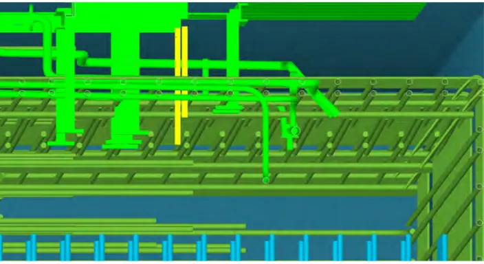
Bechtel is currently exploring use of TEKLA as a rebar modelling tool to head off potential interferences and congestion. This exercise is still in its initial phase. The idea is to develop tools that would allow designers to model all the components/embedments from various trades within concrete elements. Figure 2 shows a sample of TEKLA model with rebar and embeds.
3.5 Use of High-Performance Concrete
After all the other ways and means of reducing rebar congestion discussed above have been implemented to the extent possible, nuclear construction is still expected to be difficult from concrete placement point of view given the amount of reinforcement and embeds involved. This is particularly true around penetrations. Also, it is expected that new generation nuclear construction will involve concrete strengths in the range of 6 – 8 ksi which will typically require relatively low water-cementitious ratios. This, together with the quality assurance requirements for concrete in nuclear construction and rebar/embed congestion and we have a major challenge ahead of us when it comes to specifying the right kind of concrete. Under these circumstances, it makes sense to use what we call as “High Performance Concrete (HPC)” which is widely used in the transportation industry to ensure long-term durability of roads and bridges in the United States. At a recent HPC workshop it was suggested that if the concrete used was produced to strictly comply with relevant code requirements it should be a high-performance concrete. American Concrete Institute defines HPC as concrete that meets special performance and uniformity requirements that cannot always be obtained using conventional ingredients, normal mixing procedures, and typical curing practices. These requirements may include the following enhancements:
1. ease of placement and consolidation without affecting strength,
3. early high strength,
4. toughness,
5. volume stability, and longer life in severe environments
Because of the potential congestion issues, it is expected that nuclear concrete will involve both high paste content as well as high range water reducing admixtures to meet both the strength and workability requirements. Additional considerations to reduce cost, creep and shrinkage and heat of hydration will also play a role in selection of ingredients to achieve an appropriate mix design that is both robust and remains stable throughout the nuclear construction.
Figure 2 Rebar/Embed Modeling using TEKLA
4
CONCLUSION
Preliminary indications are that new generation nuclear structures will need significant amount of reinforcement in order to make them conform to the current regulatory requirements, Codes and Standards. The concern is that amount of reinforcement required is likely to cause congestion and consequent concrete placement problems thus impacting constructability of new generation nuclear plant structures. This paper discusses the various causes that contribute to this situation. Several practical ways to mitigate this situation are discussed which include improving the analysis and design process to remove some of the conservatism, use of higher grade reinforcement, use of headed bars and mechanical splices instead of lap splices, modelling of rebar and embeds to head off potential interferences and last but not the least, use of a high-performance mix that improves both ease of placement and consolidation.
REFERENCES
1. Coronado, C., Malushte, S., Munshi, J., and Verma, N., “A Rational Seismic Design Approach for Reinforced Concrete Walls for Nuclear Power Plants”, 20th International Conference on Structural Mechanics in Reactor Technology (SMiRT 20) Espoo, Finland, August 9-14, 2009
2. ACI 349-01, Code Requirements for Nuclear Safety Related Concrete Structures, American Concrete Institute.
3. A 615/A 615M-04b Standard Specification for Deformed and Plain Carbon Steel Bars for Concrete Reinforcement.
4. A 706/A 706M-04b Standard Specification for Low-Alloy Steel Deformed and Plain Bars for Concrete Reinforcement.
5. ACI 349-06, Code Requirements for Nuclear Safety Related Concrete Structures, American Concrete Institute.
6. ACI 318-05, Building Code requirements for Structural Concrete and Commentary, American Concrete Institute,
7. AASHTO LRFD Bridge Design Specification, 4th Ed., 2007.
8. Mast, R., Dawood, M., Rizkalla, S. and Zia, P. “Flexural strength design of concrete beams reinforced with high-strength steel bars, ACI Structural Journal, Sept-Oct, 2008.
9. SP 179-57 Pull-out behavior of high yield strength steel deformed bars embedded in reinforced concrete, ACI Special publication.
11. Heimdahl, P. and Bianchini, A. “Ultimate strength of beams reinforced with steel having no definite yield point”, ACI Journal, December 1974.
12. ASTM A1035/A 1035M, Standard Specification for Deformed and Plain, Low-carbon, Chromium Steel Bars for Concrete Reinforcement.
13. High-strength reinforcing steel: Next generation or niche, Concrete Construction Magazine, Jan 1, 2008.
14. High-strength rebar called revolutionary, ENR August 27-Sept 3, 2007.
15. FICHE DE MODIFICATION, No 15, Jan. 1992.
16. NF A35-016-1, European specification for reinforcement, November 2007.
17. Watkins, D, Gurbuz, O., Ostadan, F. and Ma, T., “Two-step method of seismic analysis” First European Conference on Earthquake Engineering and Seismology, Geneva, Switzerland, September 2006.
18. Malvar, L. J and Crawford, J.E., “Dynamic increase factors for steel reinforcing bars”, 28Th DDESB Seminar, Orlando, FL, August 1998.
19. Flathau, W. J, “Dynamic tests of large reinforcing bar splices”, Technical Report N-71-2, US Army Engineer Waterways Experiment Station, Vicksburg, MS, April 1971.
20. Bournonville, M, Dahnke, J and Darwin, D, “Statical analysis of the mechanical properties and weight of reinforcing bars”, A report on research sponsored by University of Kansas Structural Engg and Materials Laboratory, December 2004.