ISSN (Online) : 2319 - 8753
ISSN (Print) : 2347 - 6710
I
nternationalJ
ournal ofI
nnovativeR
esearch inS
cience,E
ngineering andT
echnology An ISO 3297: 2007 Certified Organization Volume 4, Special Issue 3, March 2015First National Conference on Emerging Trends in Automotive Technology (ETAT-2015)
Organized by
SAE INDIA Velammal Collegiate Club, Velammal Engineering College, Chennai, India on 20th March 2015
Structural Optimization & Analysis of Heavy
Steel Beam for Reduction of Material & Stress
Using ABAQUS FE Package
O.M.kannan1, Dr. A. kumaraswamy2, S.Ramakrishna3
M.Tech Student, Department of Mechanical, Defence Institute of Advance Technology, Pune, India. 1
Associate Professor, Department of Mechanical, DIAT, Deemed University, Pune, India. 2
Scientist ‘F’- VRDE, DRDO, Ahmednagar, Maharashtra, India. 3
ABSTRACT: This paper presents a procedure to obtain the optimal design and structure analysis of Heavy beam for
reduced stress and material. Structural Optimization is used to obtain an optimized shape, and size for specified loads and constraints within available design space. Typically, heavy beam is the main structural part of handling/articulating heavy load system like heavy Load transporter ,crane, Tower lifter, etc. The heavy load is transported and articulated (0-90deg) through the Beam by pair of hydraulic cylinders for launching purpose. Every extra pound of beam weight increases the total weight of vehicle, which causes increasing manufacturing cost, lower fuel efficiency and reduces vehicle payload capacity. With this concept of reducing weight and stress reduction, the optimized model of heavy beam is modeled and analyzed. Four models of beam are considered and modeled in ABACUS package. With the optimized parameters, optimized Model is developed and analyzed, stress analysis is carried out and the results are obtained.
KEYWORDS:Heavy beam, Static Structural analysis, ABAQUS
1. INTRODUCTION
This paper deals with design optimization of Heavy beam with the aim of reducing weight and stress for constant load, various constrains and design space. Optimization is a technique that deals with computing minima or maxima of functions subjected to design variables or constrains. Since in any practical situation, effort required for an optimal solution can be expressed as a function of certain design variables, the optimization techniques can be used to obtain the best results. The present work is carried out regarding the design optimization of a heavy beam structure by considering different models and the results obtained are analyzed and tabulated for comparison. The whole challenging task, starting with pre processing, solving and post processing is completed using ABAQUS 6.10 FE package.
II. PROBLEM DESCRIPTION
(a) (b)
Fig. 1: Heavy beam (a) articulation start mode in Transport Vehicle (b) articulation end mode in Transport Vehicle
III. OBJECTIVE
The main objectives of the work is
To reduce beam weight.
To determine the critical point having highest stress and deflection.
To optimize the design of beam structure in terms of reducing weight and stresses.
IV. METHODOLOGY
The methodology of work is outlined below
Geometric modeling of four models of heavy beam is done using ABAQUS 6.10.
Static analysis for four models of beam for same geometric features, boundary condition and loading
conditions. In order to solve the problem of the project, a detailed finite element analysis is proposed to determine the total deformation and von-misses stress in static condition using the analysis software of abacus workbench.
After analyzing the four models, a fifth model (optimized) is developed and analyzed.
V. DESIGN PARAMETER DETAILS
The design parameters are listed below
Body Specifications for five Models
Load on heavy beam : 14.99 tons
Steel : SAILMA 550
Elastic Modulus : 2.1E+11 N/m2
Poisson’s Ratio : 0.3
Mass Density : 7850 kg/m3
Yield Stress : 550E+06 N/m2
ISSN (Online) : 2319 - 8753
ISSN (Print) : 2347 - 6710
I
nternationalJ
ournal ofI
nnovativeR
esearch inS
cience,E
ngineering andT
echnology An ISO 3297: 2007 Certified Organization Volume 4, Special Issue 3, March 2015First National Conference on Emerging Trends in Automotive Technology (ETAT-2015)
Organized by
SAE INDIA Velammal Collegiate Club, Velammal Engineering College, Chennai, India on 20th March 2015
VII. DESIGN CONSTRAINTS
Height
Width
VIII. MODELING AND ANALYSIS 8.1. Modeling
The geometries under consideration are generated in the abacus package. It is a powerful program used to create complex designs with great precision. The five models are considered as viz., Model I, Model II and Model III, Model IV, Model V (optimized).
8.2. Geometric Model of Beam
Geometric model of beam is depicted below and is generated in abacus package. The material of beam is steel with 550MPa of yield strength. The other properties of beam material are mentioned in Para 5.
8.3. Loading:
The heavy beam model is loaded by static forces is 14.99 tons. The load is assumed as a concentrated force.
8.4. Boundary condition
Heavy Beam is supported by tilt cylinder and rear hinge
Constraints DOF
Cylinder hinge support 12345 =0
Beam hinge support 12345 =0
8.5 Meshing
Quadrilateral Element (S4R) is used for meshing and meshing convergence has been done. S4R 4-node is
general-purpose shell, reduced integration, hourglass control, finite membrane strains, robust and is suitable for a wide range of applications.
IX. MODEL –I
SAE INDIA Velammal Collegiate Club, Velammal Engineering College, Chennai, India on 20 March 2015
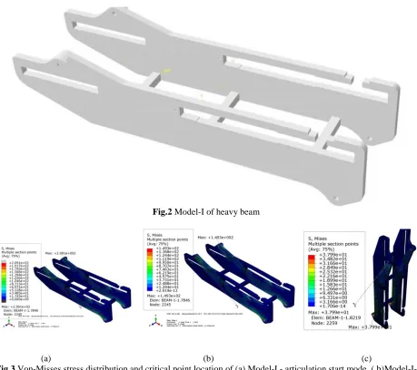
Fig.2 Model-I of heavy beam
(a) (b) (c)
Fig.3 Von-Misses stress distribution and critical point location of (a) Model-I - articulation start mode ( b)Model-I-
5deg articulated mode (c) Model-I- articulation end mode
X. MODEL –II
ISSN (Online) : 2319 - 8753
ISSN (Print) : 2347 - 6710
I
nternationalJ
ournal ofI
nnovativeR
esearch inS
cience,E
ngineering andT
echnology An ISO 3297: 2007 Certified Organization Volume 4, Special Issue 3, March 2015First National Conference on Emerging Trends in Automotive Technology (ETAT-2015)
Organized by
SAE INDIA Velammal Collegiate Club, Velammal Engineering College, Chennai, India on 20th March 2015
(a) (b)
Fig.4 (a) Model-II of heavy beam, (b)Von-Misses stress & deflection at critical point location of Model-II
X1. MODEL –III
The model-III of beam structure is modeled abacus and shown in fig 5(a). The side plate thickness is 10 mm and Top plate thickness is 10mm. The cut has been made at front side of beam the mass of beam is 4.35 tons. The stress and deflection plot for three cases is given in fig 5(b).
(a) (b)
Fig.5 (a) Model-III of heavy beam (b)Von-Misses stress and deflection at critical point location of Model-III
XII. MODEL –IV
SAE INDIA Velammal Collegiate Club, Velammal Engineering College, Chennai, India on 20 March 2015
(a) (b)
Fig.6 (a)Model-IV of heavy beam (b) Von-Misses stress distribution and critical point location of Model-IV
XIII. MODEL –V (OPTIMIZED)
The optimized design of heavy beam structure model-V is modeled abacus and shown in fig 7. The plate thickness of complete model is 10 mm. Design by size optimization is considered for three load cases followed by adjustment of cut outs for maintaining C. G. location of heavy Beam. The mass of beam is 3.98 tons. The cut outs also made based on material distribution & stress concentration and weight of beam is reduced by one tone & maximum stress reduced by 23 mpa for articulation start mode. The stresses plot for three cases is given in fig 8, 9, and 10.
ISSN (Online) : 2319 - 8753
ISSN (Print) : 2347 - 6710
I
nternationalJ
ournal ofI
nnovativeR
esearch inS
cience,E
ngineering andT
echnology An ISO 3297: 2007 Certified Organization Volume 4, Special Issue 3, March 2015First National Conference on Emerging Trends in Automotive Technology (ETAT-2015)
Organized by
SAE INDIA Velammal Collegiate Club, Velammal Engineering College, Chennai, India on 20th March 2015
Fig.9 Von-Misses stress distribution and critical point location of Model-V-5 deg articulated mode.
Fig.10 Von-Misses stress distribution and critical point location of Model-V-articulation end mode.
XIV. RESULTS AND DISCUSSION
The weights of the models are shown in the Table.1and fig 11 and the weight of the optimized model is 3.98 tons. It is giving a saving in weight of one tone (20%) comparing with Model-I.
Case I; Articulation start mode.
Case II; Five deg articulated mode
SAE INDIA Velammal Collegiate Club, Velammal Engineering College, Chennai, India on 20 March 2015
SL NO PLATE
THICKNESS (mm)
MASS (tons)
VON-MISES STRESS (mm)
MAXDEFORMATION (mm)
Case: I Case :II Case ;III Case: I Case :II Case ;III
Side plate
Top plate MODEL-
I
10 16 4.98 209.1 149.3 42.97 10.71 6.47 1.10
10 12 4.80 207.7 147.9 39.04 11.19 6.75 1.15
MODEL-II 10 12 4.23 214.0 144.4 42.97 17.96 10.86 1.88
MODEL-III
10 10 4.35 248.7 168.5 46.80 17.58 10.60 1.87
MODEL-IV
10 10 4.21 234.9 159.8 42.27 14.83 9.01 1.47
MODEL-V 11 10 4.33 186.2 125.5 44.37 17.39 10.54 1.98
10 12 4.07 200.2 133.8 43.31 18.32 11.11 1.87
optimized 10 10 3.98 187.6 133.9 47.5 18.76 11.38 1.92
Table1. Comparisons of Mass, total deformation and von-misses stress values of five models
Fig.11 model vs. mass
ISSN (Online) : 2319 - 8753
ISSN (Print) : 2347 - 6710
I
nternationalJ
ournal ofI
nnovativeR
esearch inS
cience,E
ngineering andT
echnology An ISO 3297: 2007 Certified Organization Volume 4, Special Issue 3, March 2015First National Conference on Emerging Trends in Automotive Technology (ETAT-2015)
Organized by
SAE INDIA Velammal Collegiate Club, Velammal Engineering College, Chennai, India on 20th March 2015
Weight reduction of optimized model comparing with the other fo ur models is 15.1%,
12.6%,15.4% and 20.08 %respectively.
By weight reduction, the material cost and fabrication cost is reduced for the beam/vehicle.
ACKNOWLEDGEMENT
The authors are indebted to Dr Manmohan Singh, Director VRDE, and DRDO for his support and motivation for completing this task.
REFERENCES
[1]Design Optimization of Tipper Truck Body, International Journal of Engineering Research and Development (IJERD) Volume 4, Issue 9
(November 2012).
[2]Optimization of Weight and Stress Reduction of Dump for Automotive Vehicles, International Journal of Engineering Research & Technology (IJERT) Vol. 2 Issue 10, October – 2013.
[3] Finite Element Analysis and Topography Optimization of Lower Arm of Double Wishbone Suspension Using Abacus and Optistruct, International Journal of Engineering Research and Applications (IJERA) Vol. 4, Issue 7(Version 6), July 2014.
[4]Topology optimization for fused deposition modeling process, The Seventeenth CIRP Conference on Electro Physical and Chemical Machining (ISEM), Procedia CIRP 6 (2013) 521 – 526.