Copyright to IJIRSET www.ijirset.com 315
Artificial Vision for the Blind Using
Motion
Vector Estimation Technique
Binsy N Rashad1, Nishadha S.G2
Final year Mtech Student, Dept of Computer Science, Mohandas College of Engineering, Anad, Kerala, India1
Assistant Professor, Dept of Computer Science, Mohandas College of Engineering, Anad, Kerala, India2
ABSTRACT: Blind person can be given artificial vision to know the locations of the pedestrians or moving objects around them. This paper proposes a system for detection of obstacles moving in front of a person on a walk by a camera. The system senses if a moving object in front of the person is going to hit him/her in the near future by analyzing the motion vectors acquired on the camera images. Finally the system will notify the user as these sentences "object is coming towards"," object is going away" and " chance of collision". In this way, the proposed system helps safe walking of a visually impaired person. The proposed method perform comparative study of different kind of corner detectors such as SUSAN, CSS, NOBLE and Harris corner detector and also compare different feature trackers such as Lucas- Kanade-Tomasi feature tracker. Thus suggest a better combination of feature detectors- feature tracker technique.
KEYWORDS: Motion vector estimation, optical flow, Feature tracker, Harris corner detector, Lucas- Kanade tracker.
I. INTRODUCTION
Copyright to IJIRSET www.ijirset.com 316
II. EXISTINGSYSTEMS
There are several technologies are proposed to assist safe walking of a visually impaired person. The different stage of existing system from early days to present stage is categorized into 3 main stages. The existing three methods are traditional methods, ultrasonic or Laser sensors and vision sensors
At early days, blind and visually impaired people have used some methods and devices, such as long white cane or guide dog, to aid in mobility and to increase safe and independent travel.
Due to the development of modern technology, many different types of navigational assistant devices are now available to assist the blinds. They are commonly known as ETAs. Electronic Travel Aids (ETAs) are the devices that aim conveying information about the environment to visually impaired individuals, so that they can exploit a part of the information that sighted people normally used to experience and navigate. ETAs use ultrasonic or laser sensors to detect the obstacles in their path and information is conveyed to the blind user as vibration signals or as sound signals.
The market acceptance of ETA devices is rather low as useful information obtainable from it is not significantly more than that from the long cane and responses received from it are not user-friendly. So recent research efforts are being directed to produce new navigational systems in which a digital video camera is used as vision sensor.
A .Traditional Methods
At early days, blind and visually impaired people have used some methods and devices, such as long white cane or guide dog, to aid in mobility and to increase safe and independent travel.
Guide dogs are assistance dogs; trained to lead visually impaired people to detect obstacles analyse complex situations such as cross walks, stairs, potential danger, know paths and more. Most of the information is passing through tactile feedback by the handle fixed on the animal. But guide dogs are still far from being affordable and their average working time is limited to an average of 7 years. Training of dog takes time and it is expensive too. It is obvious that growing up guide dogs takes time and money. Moreover their life span is much shorter than a human for living together with the dog whole of the human life.
The most successful and widely used travel aid for the blind is the white cane. The walking cane is a simple and purely mechanical device dedicated to detect static obstacles on the ground, uneven surfaces, holes and steps via simple tactile-force. The white cane is inexpensive, and is so lightweight and small that it can be folded and tucked away in a pocket. The length of a white cane depends upon height of the user and extends from the ground to the user’s sternum. This device is light, portable and dynamic to environment. But range limited to its own size and it is not usable for dynamic obstacles detection neither than obstacles not located on the floor.
A. Ultrasonic or laser sensor methods
Copyright to IJIRSET www.ijirset.com 317
time. These devices are all based on producing beams of ultrasound or laser light. In such a system, the device receives reflected waves and produces either an audio or vibration in response to nearby objects.
1. C-5 Laser Cane: The C-5 Laser Cane was introduced by Benjamin in 1973. It is based on optical triangulation with three laser diodes and three photo-diodes as receivers. Triangulation is the process of determining the location of a point by measuring angles to it from known points at either end of a fixed baseline, rather than measuring distances to the point directly. The C-5 Laser Cane emits pulses of infrared, which reflected from an object in front of it, are detected by a photodiode placed behind a receiving lens. The angle made by the diffuse reflected ray passing through the receiving lens gives the distance to the object detected. The laser system measures the distance to the obstacle and a sound tone proportional to this distance is played. Thus by analysing sound tone, the user can understand how far the obstacle is. That is higher sound tones indicate farthest object and lower sound tone for nearer object.
2. Mowat Sensor: The Mowat Sensor is an example of a pocket-sized device containing an ultrasonic air sonar system. When it detects an obstacle, the device vibrates, thereby signalling the user. It is a lightweight, hand-held device which has similar properties to a flashlight. The sensor itself detects objects by measuring the distance of a vibration of the brief pulses of high frequency sound it emits. The device will then tell the person how close an object may be.
3. Sonic Pathfinder: The SP is an ultrasonic sonar device designed to provide object preview in and to the side of one's path of travel for blind or visually impaired persons. The transmitting transducers flood the field in front of the traveller with ultrasonic energy. The receiving transducers detect the signals bounced back from objects in its path. These are processed by a microcomputer and translated into musical notes over miniature speakers for the traveler. The auditory signal that alerts the traveler to objects in the path corresponds to notes on the musical scale analogous to distance. As the traveler gets nearer to the object, its signal becomes correspondingly lower in tone.
Three fundamental shortcomings can be identified in all ETAs discussed in the foregoing sections [5]:
The user must actively scan the environment to detect obstacles (no scanning is needed with the Sonic Pathfinder, but that device doesn't detect obstacles at floor level). This procedure is time-consuming and requires the traveller's constant activity and conscious effort.
The traveller must perform additional measurements when an obstacle is detected, in order to determine the dimensions of the object. The user must plan a path around the obstacle) Again, a time-consuming, conscious effort that reduces the walking speed.
One problem with all ETAs based on acoustic feedback is their interference (called masking) with the blind person's ability to pick up environmental cues through hearing.
C.Vision sensor methods
The market acceptance of ETA devices is rather low as useful information obtainable from it is not significantly more than that from the long cane and responses received from it are not user-friendly. So recent research efforts are being directed to produce new navigational systems in which a digital video camera is used as vision sensor. Some of these ETA devices are vOICE [6], NAVI [3] and Equivalent point method [2]. Vision sensor method is cheap, portable and low power and is flexible to dynamic environment.
Copyright to IJIRSET www.ijirset.com 318
2. NAVI (Navigation Assistant for Visually Impaired person): NAVI is a small, light-weight device that can be attached to a cane or individual. The users are informed of objects in a room by audio and haptic feedback technologies. In NAVI, the captured image is resized to 32 X 32 and the gray scale of the image is reduced to 4 levels. With the help of image processing technique the image is differentiated into objects and background. The objects are assigned with high intensity values and the background is suppressed to low intensity values. Here the processed image is converted into stereo sound where the amplitude of the sound is directly proportional to intensity of image pixels. The limitation of vOICE and NAVI are: In vOICE, the pixel intensity is directly converted into loudness without any image processing effort to enhance the object properties. But the sound produced from the unprocessed image will contain more background information rather than object. This problem is eliminated in NAVI since it use processed image. With the help of image processing techniques the image is differentiated into objects and background. This helps the sound produced will contain more information about object. Both in vOICe and NAVI, the distance between the user and the obstacle cannot be obtained directly by the users since vOICE and NAVI use single camera. Using single camera, effective distance measurement cannot obtain directly. Both methods deal with static images only.
3. Motion vector estimation technique: Kanayama A [1] proposed a system supports safe walking of blind people. The system is equipped with a single camera placed on the chest of a person and a wearable computer, and it detects moving objects from the camera images by analysing optical flows or motion vectors. Once the system judges that a moving object in the camera scene coming straight to the user, the system calculates the line of collision between user and obstacle. If it coincides, then there is a chance of collision and gives him/her a warning by speaking to him/her. The camera images when walking usually contain vertical vibration caused by the walk of a user. It is necessary to eliminate this vibration from the camera images. Feature points in the images are then extracted and tracked to yield motion vectors. By analysing the motion vectors, the object is judged if it is coming closer to the user or going away from him/her.
.
III. PROPOSED METHOD
The proposed method is completely based on Kanayama A’s motion vector estimation technique [1] which detects moving objects from the camera images by analysing optical flows or motion vectors.
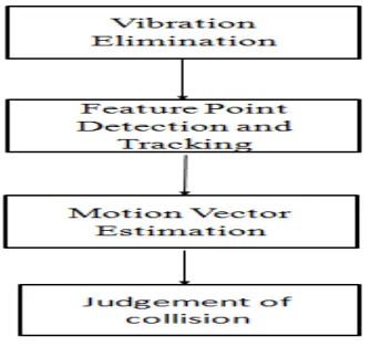
The flowchart of the proposed method is shown in Figure 3.1. The captured video frames will contain up-and-down vibrations caused due to the walk of user. First the elimination of vibration is performed in order to acquire stable images. The frames without vibration are given to the next stage where strong feature points are detected. The relevant feature points are extracted and then feature points are tracked using feature trackers which yield motion vectors to detect moving objects. Then, by analysing the motion vectors, it is judged if the detected moving object will move towards the user or move far away from the user. If it moves towards the user, then the size of the object in the image frame is calculated. If the area exceeds a threshold value ,then there is chance of collision and the system will notify the user as these sentences "object is coming towards","object is going away" and "chance of collision”. The system continuously speaks ‘chance of collision’ until the person deviates from his/her position to a safer area.
The proposed system undergoes mainly four steps. They are vibration elimination, feature point extraction, feature tracking and motion vector estimation.
Copyright to IJIRSET www.ijirset.com 319
A. Vibration elimination
The captured video contains vertical vibration caused due to the walk of user. The vibration elimination undergoes mainly 3 phases. They are feature detection and extraction, matching feature detection and transformation
1. Feature detection and extraction: In this phase, the corners of two frames (suppose frame A and frame B) are detected using FAST algorithm and then the relevant detected features are extracted.
2. Matching feature detection: Due to the vibration, the position of extracted feature of frame B may change. So in order to eliminate the vibration, the feature should bring into its original position. For that the matching features of frame A and frame B should be detected. That is corners of the frame A corresponds to the frame B should detected.
3. Transformation: This phase is done in order to bring the corner into its original position. For this purpose, apply geometric transformation which performs projective or affine transformation to an image. Not only affine transformation but also the translation, rotation and scaling is calculated. Thus the vertical vibration is eliminated
Fig 3.1: Flowchart of proposed system
.
B. Detecting feature points
In order to detect exact optical flows, it is indispensable to choose strong feature points. So the selection of strong feature point detector is the prior and important phase of the proposed method. In this paper, a comparative study of four representative corner detectors [14] are performed which are suitable for real time applications such as camera calibration and motion tracking: Harris [9], Noble [10], SUSAN [11], and CSS [12] corner detectors. So the best corner detector suitable for the proposed method is obtained from this comparative study.
C. Feature tracking
Copyright to IJIRSET www.ijirset.com 320
D. Motion vector estimation
The vector connecting the position of a feature point on the present image and its next position on the next image is a motion vector or an optical flow vector. Then, by analysing the motion vectors, it is judged if the detected moving object will move towards the user or far away from the user. The judgement of collision is done by specifying a threshold value to the size of image frames and if the size of image exceeds the threshold value, the system speaks as ‘ collision’ in order to inform the user.
Fig 1.2: Pyramidal representation of an image [1]
IV.EXPERIMENTALRESULTS
Copyright to IJIRSET www.ijirset.com 321
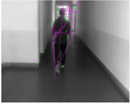
Fig 3.1: A pedestrian is coming closer to the camera in which direction of motion vectors (pink lines) are pointing forward
If the person is coming towards camera, the fear of collision (Figure 3.3) is encountered after the size of frame exceeds a threshold value. Both Figure 3.1 and Figure 3.3 are image frames of a pedestrian moving towards camera but the size of pedestrian is larger in Figure 3.3 when compared to that of Figure 3.1. It shows the image size of Figure 3.3 exceeds threshold values and it cause collision. In that case, the system will speak ‘collision’ and the sound continues until it deviate his position to a safer area.
Fig 3.2: A pedestrian is going away from camera
Copyright to IJIRSET www.ijirset.com 322 Fig 3.3: A pedestrian is coming towards camera whose
image size exceeds threshold value (case of collision)
V.CONCLUSION
The proposed system aims at providing safe walk of a blind person in a dynamic environment. This paper proposed a system for detecting persons in front of a moving camera and judging if some of them are walking toward the camera or walking away from the camera. The proposed system uses a single camera instead of a stereo camera system, so that it is easy to mount on the body and affordable too. While using single camera, distance measurement is not so accurate. Instead of distance measurement, motion vector estimation is done in the proposed system so that single camera is sufficient for this method. Moreover that ,a comparative study of different kind of corner detectors such as SUSAN, CSS, Noble, Harris corner detector is done and also compare different feature trackers too. Finally the proposed system will suggests a better combination of feature extractor- motion vector estimation technique suitable for blind navigation assistant devices
REFERENCES
[1]. Kanayama, A.,JooKooi Tan. , Hyoungseop Kim., Ishikawa S., "A camera-computer system to support safe walking of a blind person",Control, Automation and Systems (ICCAS), 2012 12th International Conference on
[2] . NazliMohajeri, RoozbehRaste, SabalanDaneshvar, "An Obstacle Detection System for Blind People", Proceedings of the World Congress on Engineering 2011 Vol IIWCE 2011, July 6 - 8, 2011, London, U.K.
[3].G. Sainarayanan, “On Intelligent Image Processing Methodologies Applied to Navigation Assistance for Visually Impaired”, Ph. D. Thesis, University Malaysia Sabah, 2002.
[4]. Steven La Grow, EdD, "The use of the Sonic Pathfinder as a secondary mobility aid for travel in business environments: a single-subject design", Journal of Rehabilitation Research and Development Vol. 36 No. 4, October 1999.
[5]. Johann Borenstein and Iwan Ulrich, "The GuideCane — A Computerized Travel Aid for the Active Guidance of Blind Pedestrians", Proceedings of the IEEE International Conference on Robotics and Automation, Albuquerque, NM, Apr. 21-27, 1997, pp. 1283-1288.
[6]. P. Meijer, “An Experimental System for Auditory Image Representations”, IEEE Transactions on Biomedical Engineering, Feb 1991, 39(2):112-121. [7]. Heyes, A., J. Visual Impair. Blindness, 1982, 76, 199–201.
[8]. Benjamin J. M., Ali N. A., A laser cane for the blind In Proceedings of the San Diego Biomedical Symposium, volume 12, pages 53-57, 1973. [9]. C. Harris, M. Stephens: “A combined corner and edge detector”, Proceedings of the 4th Alvey Vision Conference, pp.147-151, 1988. [10]. Noble, J.A.: Finding corners. Image and Vision Computing, 6(2),1988.
[11]. Smith S.M. and Brady M. SUSAN - a new approach to low level image processing. International Journal of Computer Vision, 23(1), 45-78(1997).
[12]. Mokhtarian F. and Suomela R.: Curvature scale space for robust image corner detection. Proc. ICPR, 1998.
[13]. B. D. Lucas, T. Kanade: “An interactive image registration technique with an application to stereo vision”, Proceedings of the 7th International Joint Conference on Artificial Intelligence, pp.674-679
![Fig 1.2: Pyramidal representation of an image [1]](https://thumb-us.123doks.com/thumbv2/123dok_us/1531941.1187830/6.612.202.416.282.425/fig-pyramidal-representation-image.webp)