Electronic Theses and Dissertations Theses, Dissertations, and Major Papers
1-1-1987
A micro computer based approach to machine tool selection.
A micro computer based approach to machine tool selection.
David Meloche
University of Windsor
Follow this and additional works at: https://scholar.uwindsor.ca/etd
Recommended Citation Recommended Citation
Meloche, David, "A micro computer based approach to machine tool selection." (1987). Electronic Theses and Dissertations. 6825.
https://scholar.uwindsor.ca/etd/6825
This reproduction is the best copy available.
BY
David Melache
A Thesis
submitted to the
Faculty of G r aduate Studies and Research
through the Department of
Industrial Engineering in partial fulfillment
of the r e quirements for the Degree
of Master of Applied Science at
the University of Windsor
Windsor, Ontario, Canada
IN FO R M A TIO N T O U SER S
T he quality of this reproduction is dependent upon the quality of the copy
submitted. Broken or indistinct print, colored or poor quality illustrations
and photographs, print bleed-through, substandard margins, and improper
alignment can adversely affect reproduction.
In the unlikely event that the author did not send a complete manuscript
and there are missing pages, these will be noted. Also, if unauthorized
copyright material had to be removed, a note will indicate the deletion.
UMI Microform E C 5 4 8 1 4 Copyright 2010 by ProQuest LLC
All rights reserved. This microform edition is protected against unauthorized copying under Title 17, United States Code.
ProQuest LLC
789 East Eisenhower Parkway P.O. Box 1346
©
to other institutions or individuals for the purpose of
s cholarly research.
David Meloche
I further authorize the Univer s i t y of Windsor to reproduce
this thesis by photocopying or by other means, in total or
in part, at the request of other institutions or
individuals for the purpose of scholarly research.
David Meloche
This thesis is the result o-f research carried out
in the area o-f computer aided process planning (CAPP) . The
research -focused on the use of a micro computer to aid the
p rocess engineer in the development of process plans. The
use of a micro computer was an important consideration
since it allows for a more wide spread use by todays
industries. A procedure to adequately describe the
component in terms of shapes to be removed was developed
which would allow the system to o ptimize the m achine tool
selection procedure. The research focused on the selection
of machines and the generation of cutting parameters to aid
the process engineer by speeding up the arithematic and
heuristic procedures required for the generation of process
plans. The procedure allows the system to select machines
based on the operations determined by the system, generate
the cutting parameters and rank each alternative for
selection by the process engineer. The alternatives were
ranked according to minimum cost or maximum production
rate. As a result of this research, it has been determined
that m i c r o — computers can be effectively used to aid the
process engineer in the development of process plans in
smaller machine shop environments.
I would like to take this o p po rtu nit y to thank all
the p eop le Mho helped Mith this research. A special thanks
to Dr. Dutta for his g uid e nc e and support during t he course
of this research. I Mould like to thank all the other
m e mb ers of the c om mi t te e for the re help and useful
su gge s ti o ns during the past two years. Also I Mould like to
ack no Ml e dg e the funding provid ed for this research by the
NSERC grant #9652.
A special note of thanks to Jacquie Mummery and Tom
W i lliams for there help. Also I Mould like to thank Doug
Bertram and Alf Handy for there input and help on machining
p r a ctices Mhich are used in industry.
T h is t hesis is dedicated to my Mife Debbie, Mho for the
past t Mo yea rs gav e me the e nco ura gem ent and support needed
to co mple te thi s report.
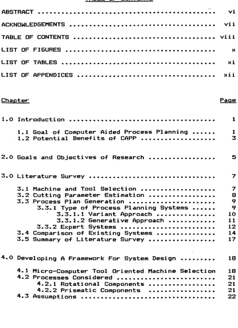
-A C K N O W L E D G E M E N T S ... vi i
T A BLE OF C O N T E N T S ... viii
LIST OF F I G U R E S ... x
L I S T O F T A B L E S ... xi
LIST OF A P P E N D I C E S ... xii
Chapter Page 1.0 I n t r o d u c t i o n ... 1
1.1 Goal o-f Computer Aided Process P l a n n i n g ... 1
1.2 Potential B e nefits of C A P P ... 3
2 .0 Goals and Objectives of R e s e a r c h ... - ... 5
3.0 Literature S u r v e y ... 7
3.1 Machine and Tool Selection ... 7
3 . 2 Cutting Parameter Estimation ... 8
3.3 Process Plan Generation ... 9
3.3.1 Type of Process Planning Systems ... 9
3.3.1.1 Variant Approach ... 10
3.3.1.2 Ge n e r a t i v e Approach ... 11
3 . 3.2 Expert Systems ... 12
3.4 Comparison of Existing Systems ... 14
3.5 Summary of Li t e r a t u r e Survey ... 17
4.0 Developing A Framework For Syst e m Design ... 18
4.1 Micro-Computer Tool Oriented Machine Selection 18 4.2 Pr o c e s s e s Considered ... 21
4.2.1 Rotational C o m p o n e n t s ... 21
4.2.2 Prismatic Co m p o n e n t s ... 21
4.3 A s s u m p t i o n s ... 22
5.1.1 M a c h i n e D a t a F i l e ... 33
5.1.1.1 M a c h i n e C h a r a c t e r i s t i c s ... 37
5 . 1 . 1 . 2 P r o c e s s C h a r a c t e r i s t i c s ... 37
5 . 1 . 1 . 3 Tool C h a r a c t e r i s t i c s ... 39
5 . 1.2 C o m ponent D e s c r i p t i o n ... 41
5.1.2.1 General I n f o r m a t i o n ... 42
5 . 1 . 2 . 2 Rotational Part D e s c r i p t i o n .... 46
5 . 1 . 2 . 3 Pr i s m a t i c Part D e s c r i p t i o n ... 49
5 . 1 . 3 S e l ection of A l t e r n a t i v e P r o c e s s e s .... 51
5 . 1 . 4 S e l ection of M a c h i n e Tool ... 55
5 . 1.5 M a x i m i z a t i o n of A l t e r a t i v e s ... 5B 5 . 1.6 Mac h i n e Tool S e q u e n c i n g ... 61
5 . 1 . 7 C o n s o l i d a t i o n Of A l t e r n a t i v e s ... 63
5 . 1.8 D e t e r m i n e M a c h i n e C h a r a t e r i s t i e s ... 65
5 . 1.9 Cost Es t i m a t i o n ... 70
5. 1.9.1 M a c h i n e T ime Per P i e c e ... 70
5. 1.9.2 Total T i m e ... 71
5. 1.9.3 Cost of Each O p e r a t i o n ... 72
5.1.9.3.1 Total Labour Cost ... 7 2 5 . 1 . 9 . 3 . 2 Total M a c h i n e Cost ... 73
5. 1 . 9 . 3 . 3 Handling Cost ... 74
5 . 1 . 1 0 Total Cost ... 74
5 . 2 System O p t i m i z a t i o n ... 75
5.2.1 O p t i m i z a t i o n of ALT1 S y s t e m ... 76
5 . 2.2 O p t i m i z a t i o n of A L T 2 S y s t e m ... 79
5 . 3 S y s t e m O u t p u t ... 82
5.3.1 ALT1 S y s t e m Output ... 83
5 . 3.2 A LT2 S y s t e m Output ... 84
5.4 Comparison of ALT1 AND A L T 2 ... 92
6.0 Conclu d i n g R e m a r k s ... 94
6.1 D i s c ussion ... 94
6.2 S c ope for Further W o r k ... 97
R e f e r e n c e s ... 99
Figure Page
3.1 Comparison of Variant and G e n e rative Approach .... 13
4.1 Illustration o-f A s s u m p t i o n s ... 23
5.1 System Flow Dia g r a m Initial System ... 26
5.2 System F low Diagram Altern a t i v e S y s t e m ... 27
5.3 Main Menu Listing ... 29
5.4 Branching From Menu to P r o g r a m s ... 31
5.5 Break-up o-f Single Mac h i n e D a t a b a s e ... 35
5.6 Illustration of Steps and T a p e r s ... 48
5.7 Illustration of Prismatic Fea t u r e s ... 50
5.8 Illustration of Al t e r n a t i v e F e a t u r e s ... 53
5.9 Determination of Speed and Feed V a l u e s ... 67
5.10 Calculation of T ime Based on Amount of Material .. 69
-Table Page
3.1 Surv e y of Computer Aided Process Planning S ystems . 16
4.1 Listing o-f Shapes to Describe Features ... 19
5.1 Codes to be Inputted in Mac h i n e F i l e s ... 38
5.2 Yes/No Questions -for Rotational C o m p o n e n t s ... 44
5.3 Yes/no Q u e stions for Prismatic Compon e n t s ... 45
5.4 Decision Table for Process Selection ... 56
5.5 Sample Output for ALT1 ... 85
5.6 Sam p l e Output for ALT2 ... 89
-Appendix Page
A. U s ers Guide ... 107
B. Flow Chart and Listing of Mac h i n e P r o g r a m ... 122
C. Description of Rotational C o m p onents ... 129
D. Description of Prismatic C o m p onents ... 135
E. Examples of the Output For ALT1 ... 140
F. Examples of the Output For A L T 2 ... 147
G. Flowchart of the Two S y s t e m s ... 160
H. Listing of the P r o g r a m s ... 170
I. Description of Input to Machine Records ... 270
-The selection of machine tools can no longer be left to
the Judgement of individuals. Markets today have forced
i n dustry to streamline production techniques to reduce
costs in all areas of manufacturing. This need to reduce
costs has resulted in the use of computers to aid in the
selection of optimal mac h i n e tools for the purpose of
process plan generation.
Process planning is the determination of the sequence
of cutting tools and the cutting parameters to manufacture
a particular component. Computerized process planning will
f orm the link between computer aided design and computer
aided manufacturing systems. This thesis discusses a
computer based approach that can be used to aid the in this
function by selecting suitable machine t o ols and generating
the cutting parameters.
1.1 G o als of Computer Aided Process Planning (CAPP)
In recent years, with the advancements which have been
made in manufacturing technology, there has been an
increased need to utilize machines to their fullest
potential. It has beco m e n e c essary to ensure that not only
-is t h e proper m a c h i n e selected for a job, but that t h e
m a c h i n i n g p a r a m e t e r s are s elected such that the part
c h a r a c t e r i s t i c s are achieved at a m i n i m u m cost. A p r o b l e m
that h a s been brought about by m o r e s o p h i s t i c a t e d m a c h i n e s
is that often the i n d i v i d u a l s developing the p l ans do not
h a v e t h e e x p e r i e n c e r e quired to a l low them to develop
p r o c e s s pla n s for the new s t yle of modern machines. Younger
m a c h i n i s t may n e ver a c h i e v e this s a m e level of experience,
s i nce the new m a c h i n e s do not r e q u i r e the same level of
m a c h i n i n g skill to o p e r a t e as t h e older manual mac h i n e s
o n c e required.
Today, the task of m a c h i n e s e l ection is often p e r formed
m a n u a l l y b y a ma c h i n i s t who selects, in his judgement, the
best c h o i c e of mac h i n e t o o l s a v a i l a b l e in t h e shop. The
m a c h i n i s t then a t t e m p t s t o d e t e r m i n e the optimal m a c hining
pa r a m e t e r s for the job based on h i s j u d gement and past
experiences. It has been rep o r t e d that in most cases the
ma c h i n i s t will choo s e the m a c h i n e which he is most familiar
with (2), which may not be the best a l t e r n a t i v e available.
T h e ideal solution would be to consider all p o s s i b l e tool
c o m b i n a t i o n s a v a i l a b l e in t h e shop, and d e t e r m i n e the most
cost e f f e c t i v e plan for t h e part to be manufactured. Until
all c o m b i n a t i o n s of t o ols can be exp l o r e d the develo p m e n t
of optimal p r o c e s s p l ans is v e r y u n l i k e l y to occur.
for manufacturing in order to ensure the best pos s i b l e
p ro c e s s plan can be generated. For small firms, a
micro-computer may be all that is required to aid in this
function, since the number of altern a t i v e m a chines would be
co n s i d e r a b l y less than in larger firms. The use of a
m i c r o -computer could be advant a g e o u s for smaller industries
since they are less exp e n s i v e and well within their
financial capabilities. Moreover memory requir e m e n t s need
not inhibit their use, since the a lternative machines
a v a i l a b l e would n ormally be less when compared to larger
industries.
1-2 Potential B e nefits of A CftPP System
Ben e f i t s other than the selection of m a c h ine-tools
which are brought about b y computer aided p r o c e s s planning
include;
1. The ability to pro d u c e plans more rapidly. The
use of a computer allows more rapid generation of process
plans. Plans that may h ave taken days to develop may only
take h o u r s with the aid of a computer. As a result there
would b e a sav i n g s in the cost of generating the plans.
2. Reduction in cost by increasing productivity.
By selecting the proper mac h i n e s and the machining
p r o d u c t i v i t y can b e a chieved s i n c e the m a c h i n e s are
ut i l i z e d to their highest potential.
3. Faster i m p l e m e n t a t i o n of new technologies. By
allowing the c omputer to select m a c h i n e s t h e i n stallation
of n e w m a c h i n e s will be i n c orporated into the sys t e m
i m m e d i a t e l y and not r e q u i r e the c o m p l e t e learning of the
m a c h i n e ’s c a p a b i l i t i e s b y the operator.
4. Lower level of m a c h i n e knowledge. S i n c e t h e
co m p u t e r is r e s p o n s i b l e for the selection of m a c h i n e tools
the operator d oes not r e q u i r e c o m p l e t e k n o wledge of all
m a c h i n i n g met h o d s available. Therefore, the higher paid
machinist are not required to ope r a t e the s y s t e m and can be
used in more important f u n c t i o n s on the shop floor.
T h e s e and other potential b e n e f i t s will result in more
wide spread u s e of c o m p u t e r s to aid in the ge n e r a t i o n of
pro c e s s plans. Computer aided p r o c e s s p lanning systems will
be i n c orporated in i n d u stries both large and small. With
this increased demand, t h e r e is a need to develop a micro
c o mputer based s y s t e m which can be used to aid in the
T h e goal of the r esearch was to d e t e r m i n e if a
g e n e r a t i v e pro c e s s planning sys t e m could be d e v eloped in a
manner r e q uiring the use of o n l y a m i c r o — c o m p u t e r ; if such
a s y s t e m w ere possible, develop a m e t h o d o l o g y to allow for
optimal process plan g e n e ration within a r e a s o n a b l e time
period. A computer with 5 1 2 K of operating m e m o r y and with a
hard disk c a p a b i l i t y of 2 m e g a b y t e s w a s s elected for the
study, since t his would con f o r m to standard m i c r o c omputer
sys t e m s n o r m a l l y used by small industry.
Based on studies and t e sts of t h e s y s t e m it was
decided that the optimal g e n e r a t i o n of p r o c e s s plans could
be left to the o p erator of the system, the o p erator then
u ses the c omputer as an aid in the s e l ection of tools and
to p r o v i d e the recomm e n d e d cutting parameters. The final
selection and s e q u encing of m a c h i n e t o ols would be left to
the o p e r a t o r of the system.
T h e thesis p r o p o s e s two s e p a r a t e m e t h o d o l o g i e s to
develop "optimum" p r o c e s s p l ans based on component
de s c r i p t i o n and c a p a b i l i t i e s of exi s t i n g m a c h i n e s on the
shop floor as fallows:
1. A ll ow for optimal g e n e r a ti on of p r o c e s s
p l a n s us ing a m i c r o - c o m p u t e r .
-2. Use a m i c r o - c o m p u t e r to aid in the
s e l ection of a p p r o p r i a t e m a c h i n e t o ols
and cutting parameters.
The two s y s t e m s have been d e v eloped and c o mpared based
on var i o u s parameter c h a r a c t e r i s t i c s and operating
Several papers were reviewed covering many different
topics related to tool selection, process plan generation
as well as papers dealing with machining processes. The
wide variety of topics reviewed indicate the d i f f i c u l t y in
developing a tool selection procedure especially using only
a micro-computer. Many pap e r s dealt with specific areas in
the field, with none providing a procedure which can be
applied to a micro-based system. The papers w ere grouped
into different categories as listed below;
1. Machine and Tool selection.
2. Cutting Parameter Estimation
3. Process planning Systems
a. Variant
b. Generative
c. Expert
1 Machine and Tool Selection
A few papers dealt with procedures which can be
■followed in the selection of machine-tools (2,8,18,19,22).
The selection of a ppropriate machine tools is one of the
most vital steps in the process planning function. It is
important to relate the machine tool c a pabilities to those
required by the component to be manufactured, and also to
-determine i-f simultaneous machining o-f the component is
possible by having more than a single cutting tool in
contact with the component at any point in time. The
selection usually involves an estimate of the machining
cost for a particular machining operation specified by the
operator. The specification of the machining operation
however, assumes that the machining operation is known. For
a truly generative system the machining process required
should be generated by the system. This would allow for
different alternative operation combinations resulting in
the same finished part.
3.2 Cutting Parameter Estimation
Once the machine has been selected for a particular
operation a number of cutting parameters must be determined
to ensure that the specifications of the component are met.
These parameters will include machine speeds, tool feeds,
etc. In all the papers some form of an assumption is made
to simplify the determination of the cutting parameters. In
some cases only a single pass was made, or the feed rate
Was fixed. Based on these assumptions, the remaining
parameters were calculated using the tool life equations.
Several papers dealt with the generation of cutting
3 . 3 P r o c e s s Plan G e n e ration
Several pap e r s dealing with p r o c e s s plan genera t i o n
w e r e reviewed. P r o c e s s pla n n i n g involves both of the
p r e v i o u s steps o-f machine-tool selection and c utting
pa r a m e t e r estimation as well as the s e q u encing of m a c h i n e s
to p e r f o r m the required operation. The overall plan should
result in the genera t i o n of a p r o c e s s plan that m e e t s the
r e q u i r e m e n t s of the part at t h e lowest cost.
3.3.1 T y p e s of Process P l anning Sys t e m s
The traditional approach to p r o c e s s pla n n i n g has been
the manual m a nipulation of information by a skilled
ma c h i n i s t to develop a p r o c e s s plan b a sed on an engine e r i n g
drawing. This approach is quickly being rep l a c e d in many
indust r i e s by c o m p u t e r i z e d a p p r o a c h e s to the problem.
T h e r e are two computer based approaches;
1. Variant
2. G e n e r a t i v e
Each of the s e a p p r o a c h e s is u n i q u e in t e rms of their method
p r o c e s s plan generation. Each will be d e s cribed in
detail as to h o w they are used to g e n e r a t e or aid in the
3.3.1.1 Variant Approach
A f e w of t h e p a p e r s dealt w ith t h e var i a n t approach of
p r o c e s s plan generation. The list of papers inc l u d e (11,
19,23). In t h e s e p a p e r s t h e main o b j e c t i v e w a s to d e t e r m i n e
an a p p r o p r i a t e coding sche m e to be used to s t ore and
r e t r i e v e existing p r o c e s s p l a n s f r o m storage. T h e
a d j u s t m e n t s to m a c h i n e selection, sequencing, and cutting
p a r a m e t e r s due to d i f f e r e n c e s in the c o m p o n e n t s was not
di s c u s s e d in detail and was often left to the individual
o p erator of t h e system.
The Variant approach in v o l v e s the c o d i f i c a t i o n of the
component based on p r e d e t e r m i n e d c o m ponent characteristics.
Common coding s y s t e m s inc l u d e t h e Opitz and M i c l a s s cod i n g
m e t h o d s (19). Based on the c ode d e vloped b y the above
i
methods, an e x i s t i n g p r o c e s s plan is re t r i e v e d f rom sto r a g e
and manual a l t e r a t i o n s are m a d e to t h e plan to a l low the
component to be m a n u f a c t u r e d to t h e new specifications.
T his p r o c e d u r e r e q u i r e s the manual m a n i p u l a t i o n of the plan
which c o uld b e subject to error or p r e j u d i c e s based on the
o p e r a t o r ’s experience. It is the potential error and
P r e j u d i c e s which h a v e to b e el i m i n a t e d in order to ensure
the ge n e r a t i o n of optimal p r o c e s s plans. T h e G e n e r a t i v e
a Pproach b r i n g s us closer t o t r uly i n d e p endent and
3.3 . 1 . 2 Generative Approach
Here also, several papers dealt with the components
which go into the development of a Generative process
planning system. These papers included (9,10,15,19,21,23).
The difficulty with these papers seemed to be the
inflexibility of the designed systems and the size of
computer which was often required to run the system. The
pap e r s dealt with systems which w ere often designed to suit
the needs of one particular user. Often the design took
many man years to develop and required a large computer
system to operate. None of the pape r s dealt with a
universal system which could be applicable to a wide number
of users through its implementation on a m i c r o - c o m p u t e r .
The Generative approach involves generating new process
p lans from the beginning each time a part is to be
manufactured. The system not only considers the part
fea t u r e s and specifications, but also the number of
components which are to be manufactured, as well as the
current machines available. In G e n e rative pro c e s s planning
the component must be u n iquely defined by the operator to
the system in terms of f e atures to be removed, the
tolerance and the surface finish of each feature. This
e n tirely new plan generation allows the sys t e m to consider
every p o ssible machine tool combination each time to ensure
complete description of all machines and tools to be kept
in a machine database. This database is used to compare the
requirements of the component with the tools available and
their capabilities.
3.3.2 Expert System
Expert systems have been designed for both the Variant
and Generative approaches to process planning. The recent
trend towards an intelligent system has prompted much
research in this area, but, it is still in its infancy.
Through the development of more powerful computers and new
programming languages such as Prolog, these system may
eventually be used to develop complete process plans with
very little interaction by the operator. A few papers were
found which, did describe systems which utilize this new
found knowledge. These include (7,10,15,17).
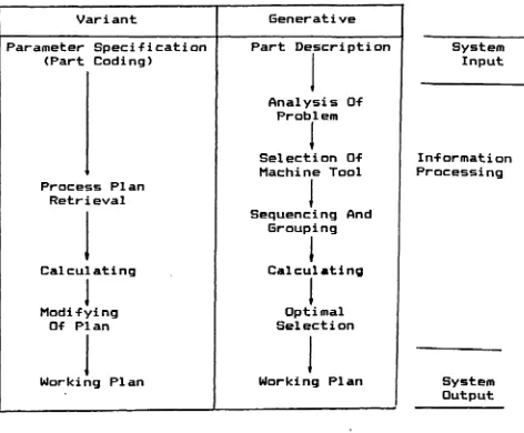
A comparison of the Variant and Generative approaches
is illustrated in Figure 3.1. Under the Variant approach
the operator of the system must carry out what is called a
"modifying" operation. The operator must take the existing
process plan and modify it to suit the characteristics of
the current problem. It is in this modification phase that
Variant Generative
Parameter Specification (Part Coding)
Process Plan Retrieval
Calculating
J
ModifyingOf Plan
Working Plan
Part Description
Analysis Of Problem
I
Selection Of Machine Tool
Sequencing And Grouping
1
Calculating
1
Optimal Selection
1
Working Plan
Comparison Of The Variant
& Generative Approaches To
Process Planning
Figure 3.1
System Input
In-formation Processing
alternative choices. The generative approach requires no
modification to the process plan, but the complexity of the
problem is greatly increased due to the enormous number of
calculations required and the number of comparisons to be
made between the machine capabilities and the component
requi rements.
3.4 Comparison Of Existing Process Planning Systems
There have been numerous attempts to develop computer
aided process planning systems with several successes in
both the Variant and Generative approaches. A third
approach which is receiving considerable attention is the
Expert system of process planning. Each of the first two
have been developed in most cases by industry to suit the
particular needs of a given company. The Expert systems
which are being developed are designed to be applicable to
more then a single user. The Expert systems have the
capability of learning from their past decisions, so that
mistakes in the past will not occur in the future. These
systems are capable of making decisions in a similar manner
to the human decision process and therefore are capable of
learning as the system is utilized. The Expert system is
not a new method of process or tool selection, but, is a
lan g u a g e s such as Prolog and Lisp.
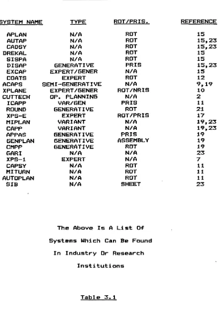
T a b l e 3.1 c o n t a i n s a listing of s y s t e m s which h ave been
d e v e l o p e d or are c u r r e n t l y in the p r o c e s s of being
developed by i ndustry or in r e search facilities. Each
s y s t e m has been broken down to a l low for compar i s o n based
on certain d e f i n i t i o n s such as; system name, t ype (variant,
g e n e r a t i v e , e x p e r t ) , c o m ponent t ype and r e f e r e n c e pap e r s
w h e r e information on the var i o u s sys t e m s can be found. N one
of the current sys t e m s re v i e w e d h ave been d e v eloped to
s p e c i f i c a l l y run on a m i c r o computer, and a great number of
t h e s e s y s t e m s h a v e been dev e l o p e d with a p a r t i c u l a r user in
mind.
An indepth rev i e w of t h e s e s y s t e m s has indicated a
d i v e r s i t y of a p p r o a c h e s to the p r o b l e m of g e n e rating
p r o c e s s plans. However, the goal of each sys t e m is to
develop a cost e f f e c t i v e plan for the user of the system.
Using cost e f f e c t i v e n e s s as a basis, the s y s t e m to be used
in ind u s t r y should also be a f f o r d a b l e for the user in terms
of the initial capital investment. In many of the c a s e s
shown in T a b l e 3.1 t h e s y s t e m could not be used by a
sma l l e r industry, or any other user s i nce it was designed
for t h e pa r t i c u l a r n e e d s of a s pecific company. For this
reason it is n e c e s s a r y to develop a method to aid in the
p r o c e s s p lanning fun c t i o n which can be used by a number of
S Y S T E M S IN INDUSTRY
S Y S T E M N AME TYPE RDT/PRIS. R E F E R E N C E
AP LAN N/A RDT 15
A U TAP N/A ROT 15,23
C A DSY N/A ROT 15,23
DRE K A L N/A ROT 15
SISPA N/A ROT 15
DISAP GE N E R A T I V E PRIS 15,23
EX CAP E X P E R T / G E N E R N/A 15
COATS E X P E R T ROT 12
ACAPS S E M I - G E N E R A T I V E N/A 9, 19
XPLANE E X P E R T / G E N E R R O T / N R I S 10
C U T T E C H OP. P L A N N I N G N/A 2
ICAPP V A R / G E N PRIS 11
ROUND G E N E R A T I V E ROT 21
XPS-E E X P E R T ROT / P R I S 17
M I P L A N V A R I A N T N/A 19,23
C APP V A R I A N T N/A 19,23
APPAS G E N E R A T I V E PRIS 19
6EN P L A N GE N E R A T I V E ASS E M B L Y 19
C MPP G E N E R A T I V E ROT 19
G A R I N/A N/A 23
XPS-1 E X P E R T N/A 7
CA PSY N/A ROT 11
M I T U R N N/A ROT 11
A U T O P L A N N/A ROT 11
SIB N/A S H EET 23
T h e A b o v e Is A List Of
Sys t e m s Which Can Be Found
In Industry Dr Research
I n s titutions
micro-computer. This report -focuses on the speci-fic
approach to develop o ptimum pro c e s s plans using process
c h a r a c t eristics based on existing machining capabilities,
and to do so solely within the limitations of a standard
m i c r o — computer system.
3 . 5 Summary of Literature Survey
F rom the review of these pape r s it was decided that a
micro-computer based system can have a large number of
b en e f i t s to a great many users, provided the system can be
designed for more then one user. Through a rev i e w of
v a r i o u s papers (14,16,24,25) it was decided that the use of
"tool life equation" te c h n i q u e s for cutting parameter
estimation would not be used due to the limited
a p plications and the size of optimization p r o cedure which
res u l t s when solving for the process pa r a m e t e r s using tool
life equations. Instead, standard cutting equations and
he u r i s t i c s can be applied to d e t ermine the individual
parame t e r s and still be able to provide near optimal
solutions.
V ar i o u s papers will be r e ferred to throughout this
report as the information from these papers is related to
T h e r e m ainder of t h i s t h e s i s will develop a pos s i b l e
design for a m i c r o - c o m p u t e r based m a c h i n e selection
procedure. Bef o r e the d e t a i l s of the syst e m can be
developed, it is n e c e s s a r y to p r o p o s e a f r a mework within
which the s y s t e m will operate.
Under no c i r c u m s t a n c e s can any model be d e v eloped to
con s i d e r all p a s s i b l e situations. T h e r e are l i m i t a t i o n s to
all sys t e m s no matter how c o m p l e t e t h e y may be. To develop
a m i c r o c o mputer based s y s t e m it was n e c e s s a r y to restrict
the s ize of the problem. Therefore, it was n e c e s s a r y to
r e s t r i c t the number of p r o c e s s e s considered, and the type
of c o m p o n e n t s which can be handled by the system. The
s y s t e m which will be d e s cribed in the su b s e q u e n t ch a p t e r s
u ses the tool o riented a p proach of matching t h e f e a t u r e s to
be rem o v e d with the tool c a p a b i l i t i e s of different
machines.
4.1 M i c r o Computer Tool O riented M a c h i n e Selection
The model is a b l e to select m a c h i n e t o ols based on the
de s c r i p t i o n of the c o m p o n e n t in t e r m s of identi f i a b l e
f e a t u r e s by the system. T h e s y s t e m is c u r r e n t l y restricted
to known f e a t u r e s which are listed in T a b l e 4.1. A detailed
L IST OF SHA P E S WHICH ARE
INCLUDED IN T H E SYSTEM
Prismatic shapes; -Rectangles
—Triangles
— Trapezoid
— Rhomboid
— Internal Keyway
-External Keyway
Rotational shapes; -External cylinder
— Internal cylinder
-Portion of a cylinder
— Tapered surfaces.
The A b ove List Of F eatures Are The
Only Features Which Are Recognized
By the System
i dent ifi cat ion is given in s ection 5.1.2. T h e number o-f
■features can be exp a n d e d to include others, but, for the
initial p r o b l e m t h e fea t u r e s in Table 4.1 w ere considered
s u f f i c i e n t for f a i r l y complex components. The system was
written in "Better Basic" which allowed the computer to use
all the av a i l a b l e m e m o r y in the computer. The system was
designed to be run on a IBM AT with a mem o r y of 5 1 2 K with
hard disk c a p a b i l i t i e s on which the machine tool records
we r e stored for faster retrieval. The system output was
p ri n t e d using a 132 column Epson printer.
It is important t o note that the p r o g r a m was written
for i n t e r a c t i v e use. The s y s t e m has been des i g n e d to be as
user f r i e n d l y as p o s s i b l e in order that it a c c o m m o d a t e non
expert o p e r a t o r s on the shop floor. In Appendix A a users
g u i d e is p rovided to aid the user with any d i f f i c u l t i e s
which m a y occur. T h ere should be little t r o u b l e in allowing
the sys t e m to be o perated by an individual who has little
kn o w l e d g e of c o m p u t e r s or the m a c h i n e selection function.
T h e initial sys t e m c o n s i d e r s a limited number of
p r o c e s s e s for rotational and pri s m a t i c components. Although
t h e number of p r o c e s s e s is limited, the c o m p l e x i t y of the
com p o n e n t can be such that the optimal s e l ection of the
m a c h i n e t o o l s b y manual m e t h o d s would p r ove to be v ery t ime
4.2 P r o c e s s e s Co n s i d e r e d
T h e p r o c e s s e s were divided among t h e two types of parts
co n s i d e r e d ( r o t a t i o n a l / p r i s m a t i c ) . T h e mac h i n e files were
des i g n e d to group the p r o c e s s e s s e p a rately to red u c e the
size of the files, and speed up the mac h i n e selection
function. The grouping p r o c e d u r e is described in Section
5.1.2.
4.2.1 Rotational c o m p o n e n t s
P r o c e s s e s included are; -Ext. Turning — Ext. Grinding — Int. Drilling — Boring
-Int. Grinding
-Ext. Drilling, Reaming -Ext/Int Key w a y s
4 . 2 . 2 Pr i s m a t i c C o m p o n e n t s
P r o c e s s e s included a r e : — End milling
-Peripheral milling - F a c e milling
— Ext. sur f a c e Grinding -Drilling, Reaming
-Boring
— Int. Grinding
As can be seen by the a b ove list, fair l y complex
p a r t s can be created sin c e t h e number and t ype of pr o c e s s e s
c o n s idered is cap a b l e of c r eating a large number of varied
4 . 3 A s s u m p t i o n s
T h e r e Mere a number of a s s u m p t i o n s m a d e throughout the
r esearch for p u r p o s e s of model development. The s e
a s s u m p t i o n s M e r e n e c e s s a r y to a l loM the sys t e m to be
ope r a t e d on a m i c r o - c o m p u t e r and pro v i d e s e l e c t i o n s in a
r e a s o n a b l e amount of CPU time. The as s u m p t i o n s made are
listed bel o M Mith a brief de s c r i p t i o n of each:
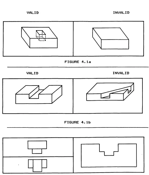
1. O n l y c o nsider rotational internal fea t u r e s for
both rotational and p r i s m a t i c components, (exclude sharp
c o r n e r s as found in pockets.) CFigure 4 . l a . 3 By making
t h i s as s u m p t i o n the t y p e of o p e r a t i o n s M ere restricted.
T his a s s u m p t i o n hoMever, does not restrict the use of
internal keyMays.
2. All f e a t u r e s must run parallel to one of the
major a xis of the component, (exclude angular cuts) CFigure
4. l b . 3 T his assump t i o n r e s t r i c t s s i m u l t a n e o u s movement in
tMO different d i r e c t i o n s by the tool.
3. O n l y c o nsider one r e p r e s e n t a t i o n of shapes:
t h o s e p rovided by the user of the system. Do not consider
other shapes Mhich can be derived from c o m b i n a t i o n s of
s h a p e s CFigure 4 . 1 c . 3 The same fea t u r e s can be created by
c o m bining other shapes. To r e strict consid e r i n g different
c o m b i n a t i o n s of f e a t u r e s o n l y the one p rovided by the
V A LID INVALID
F s ® I . . \
( \
\
\
....\
' ■ ■F I G U R E 4 . la
V A L I D INVALID
F I G U R E 4 . lb
4. T h e r e are no special tools such as form tools.
Special form too l s can c r e a t e a number of defined f eatures
simultaneously. The s y s t e m is r e s t ricted to creating a
sin g l e f e a t u r e with a tool.
5. All too l s are either HSS or Carbide. The metal
removal r ate of t h e s e t o ols will be c o n s idered to be
constant (no a l l o w a n c e for tool wear). In estimating the
tool c o s t s of machining, the tool will ope r a t e as if it
were a n e w t o o l .
6. O nly one tool can be in contact with the
c o m p o n e n t at a n y one time. T h e r e can be no s i m u l t a n e o u s
ma c h i n i n g operations.
The r e m aining a s s u m p t i o n s will be outlined as
T his chapter discusses the specific sections (modules)
•for the machine tool selection procedure. The first step in
the d evelopment of a machine selection p r o cedure is the
t ransformation of component fe a t u r e s into alternative
processing methods. Once this relationship has been
established a v a ilable machining capabi l i t i e s are examined
to c o r relate the a lternative processes to the machine tools
a v a ilable on the shop floor. The last step is to use a cost
justification approach to derive a combination of machine
too l s to generate various c o m b i n a t i o n s of components. A
unique feature of this approach has been the incorporation
of batch sizing of the c o m p o n e n t s into the cost
justification system.
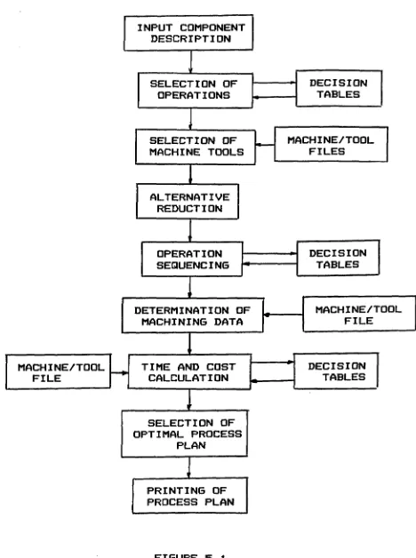
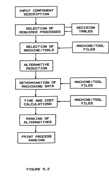
Figures 5.1 and 5.2 contain a f low diagram of the two
ap p r o a c h e s taken to aid in the generation of process plans.
For the remainder of this report the two approaches will be
called ALT1 and ALT2 respectively. The difference between
the two systems is that in ALT1 a sequencing of operations
is carried out to d e t ermine the optimal s e quence of m achine
tools, whereas ALT2 does not sequence the operations, but
leaves the sequencing to the operator of the system. In
both cases the pr o c e d u r e r a nks the a lternative outputs
based on min i m u m cost, A LT2 also ranks the output by
-D E C I S I O N T A B L E S
D E C I S I O N T A B L E S D E C I S I O N T A B L E S
O P E R A T I O N S E Q U E N C I N G A L T E R N A T I V E R E D U C T I O N
M A C H I N E / T O O L F I L E
M A C H I N E / T O O L F I L E S S E L E C T I O N O F
O P E R A T I O N S
M A C H I N E / T O O L F I L E
P R I N T I N G OF P R O C E S S P L A N
S E L E C T I O N O F M A C H I N E T O O L S
T I M E A N D C O S T C A L C U L A T I O N INPUT C O M P O N E N T
D E S C R I P T I O N
D E T E R M I N A T I O N O F M A C H I N I N G D A T A
S E L E C T I O N O F O P T I M A L P R O C E S S
DECISION TABLES
AL T E R N A T I V E RE D U C T I O N
M A C H I N E / T O O L F I LES M A C H I N E / T O O L
FILES
R A N K I N G OF A L T E R N A T I V E S
MA C H I N E / T O O L FIL E S
P R I N T PRO C E S S R AN K I N G
T I M E AND COST C A L C U L A T I O N S
S E L E C T I O N OF M A C H I N E / T O O L S INPUT C O M P O N E N T
D E S C R I P T I O N
D E T E R M I N A T I O N O F M A C H I N I N G DATA
S E L E C T I O N OF R E Q U I R E D P R O CESSES
m a x i m u m pr o d u c t i o n rate.
F i g u r e 5.1 lists the m o d u l e s developed to include the
s e q u e n c i n g of the o p e r a t i o n s to d e t e r m i n e the overall
optimal process plan -for ALT1. For A L T 2 as shown in F i g u r e
5.2 t h e r e is no sequen c i n g of operations; instead the
s y s t e m ge n e r a t e s and r a nks the a l t e r n a t i v e mac h i n e t o ols
for each required operation. The ranking is based on either
m i n i m u m cost or max i m u m pr o d u c t i o n rate. Each module in
F i g u r e s 5.1 and 5.2 will be d e s cribed as to its c ontents
and the function it p e r f o r m s in the program. Several of t h e
m o d u l e s of F i g u r e s 5.1 and 5 . 2 are identical in design and
function; in t h e s e i n s tances only a sing l e d escription will
be provided. However, when d i f f e r e n c e s between the two
p r o c e d u r e s exist, the m o d u l e will be discussed separately.
U n l i k e s o m e s y s t e m s which r e q u i r e the user to input
i nformation using a card deck or in the form of a data
file, t his system is d e s i g n e d to be user interactive. The
system p r o m p t s the ope r a t o r to d e s c r i b e the part in t e rms
of t h e raw d i m e n s i o n s and f e a t u r e s to be machined.
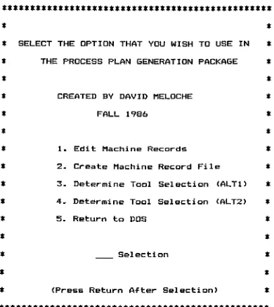
Upon start up of the system, the user has a number of
a l t e r n a t i v e c h o i c e s in the f o r m of a menu from which to
choose. Upon s e l ection of an op e r a t i o n to be p e r formed the
s y s t e m will t r ansfer to the a p p r o p r i a t e p r o g r a m and begin
execution. The main m e n u of t h e s y s t e m is shown in F i g u r e
**********************************************
S E L E C T T H E O P T I O N T H A T YOU WISH T O USE IN
T H E P R O C E S S P L A N G E N E R A T I O N PAC K A G E
C R E A T E D B Y D A V I D MEL O C H E
F A L L 1986
1. Edit M a c h i n e Rec o r d s
2. C r e a t e M a c h i n e Record File
3. D e t e r m i n e Tool S e l ection (ALT1)
4. D e t e r m i n e Tool Se l e c t i o n (ALT2)
5. Ret u r n to DOS
Se l e c t i o n
(Press Ret u r n After Selection)
* * * * * * * * * * * * * * * * * * * * * * * * * * * * * * * * * * * * * * * * * * * * * *
Illustration of main m enu of p r o g r a m
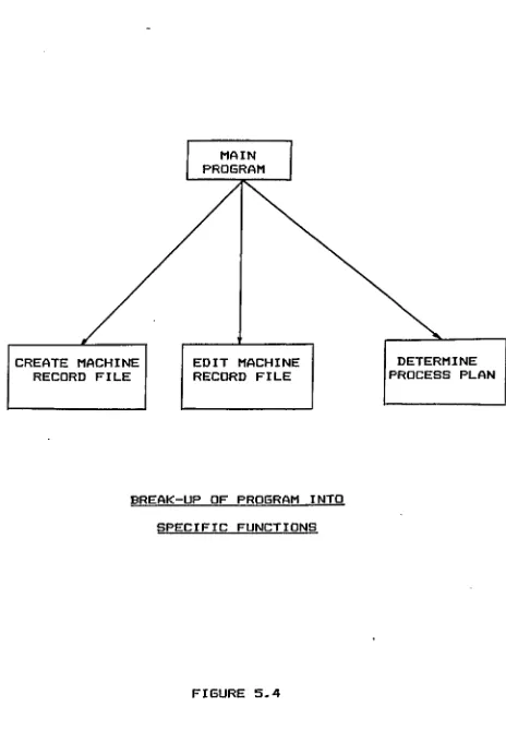
des i r e d p r o g r a m which the o p e r a t o r selected. By selecting
t he p r o g r a m to be loaded, the amou n t of m e m o r y required to
s t o r e t h e p r o g r a m is reduced t h u s making m e m o r y a v a ilable
for other a p p l i c a t i o n s in the system. A m i c r o - c o m p u t e r
based s y s t e m r e q u i r e s e f f e c t i v e use of a v a i l a b l e m e m o r y in
order to h a n d l e the c o m p l i c a t e d ana l y s i s and the sto r a g e
c a p a c i t y re q u i r e d to d e v e l o p a p r o c e s s pla n n i n g system.
F i g u r e 5.4 i l l u s t r a t e s t h e p r o c e d u r e of b r a nching to
d i f f e r e n t p r o g r a m s by the s y s t e m in order to "free up"
a v a i l a b l e m e m o r y by not havi n g all the p r o g r a m s loaded
simultaneously.
The m odular design and b r a n c h i n g t e c h n i q u e s were
f a l l o w e d t h r o u g h o u t t h e d e v e l o p m e n t of the system. In
s u b s e q u e n t sections, t h e b r e a k u p of the m a c h i n e f i les and
t h e co m p o n e n t d e s c r i p t i o n i nto m o d u l e s w e r e n e c e s s a r y to
m ake the e n t i r e s y s t e m m ore efficient.
5.1 D e v e l o p m e n t of S y s t e m M o d u l e s
A s shown in F i g u r e s 5.1 and 5 . 2 the task of p r o c e s s
p l a n n i n g can be divided into several mod u l e s as listed
below;
1. M a c h i n e d e s c r i p t i o n
2. C o m p o n e n t d e s c r i p t i o n
M A I N P R O G R A M
D E T E R M I N E P R O C E S S P L A N E D I T M A C H I N E
R E C O R D F I L E C R E A T E M A C H I N E
R E C O R D F I L E
B R E A K - U P O F P R O G R A M INTO
S P E C I F I C F U N C T I O N S
4- Sel e c t i o n of m a c h i n e t o ols
5- Ope r a t i o n s e q u e n c i n g
6. Gr o u p i n g of o p e r a t i o n s
7. D e t e r m i n a t i o n of ma c h i n i n g c h a r a c t e r i s t i c s
8. T i m e and cost c a l c u l a t i o n s
9. S e l e c t i o n of best p r o c e s s plan
10. P r inting of p r o c e s s sheet.
B ased on t h e s e modules, it is fea s i b l e that an optimal
p r o c e s s plan can be ge n e r a t e d as outlined in Fig u r e 5.1. It
will be shown however, that t h e genera t i o n of the optimal
p r o c e s s plan m a y not p r o v i d e the most useful i nformation to
t h e operator. T h e g e n e r a t i o n and ranking of a l t e r n a t i v e s
for each re q u i r e d op e r a t i o n would p r o v i d e m o r e information
to t h e ope r a t o r of t h e system. The s y s t e m would all o w the
o p e r a t o r to select which m a c h i n e to use for an operation
f r o m t h e m a c h i n e s which are c u r r e n t l y available. In the
c a s e of a rush job, w h e r e the m a c h i n e in the optimal
p r o c e s s plan m a y not be available, the ope r a t o r can select
an a l t e r n a t i v e machine. Also, t h e r e will be increased
f l e x i b i l i t y in scheduling, by a v oiding the over sc h e d u l i n g
of a pa r t i c u l a r m a c h i n e based on set optimal p r o c e s s p l ans
as de t e r m i n e d by ALT1.
B e f o r e t h e p r o g r a m can run, a c o m p l e t e d e s c r i p t i o n of
a c c e s s i b l e database. Therefore, b e f o r e descri b i n g the
m a c h i n e tool s e l e c t i o n p r o c e d u r e the logical order would be
t o develop the m a c h i n e tool d a t a b a s e s i nce t his s e r v e s as
t h e c o r n e r s t o n e for de r i v i n g the p r o c e d u r e for pro c e s s
planning.
5.1.1 M a c h i n e D a t a File
B e f o r e m a c h i n e tool s e l e c t i o n can t a k e place, a
c o m p l e t e listing of m a c h i n e s and t o o l s must exist in a
database. T h e d a t a b a s e must con t a i n the s pecific
i n f o r m a t i o n an the a v a i l a b l e m a c h i n e s and t o o l s in the shop
to a l l o w for the s e l e c t i o n of not o nly the machines, but
a l s o t h e g e n e r a t i o n of cut t i n g p a r a m e t e r s for each of the
r e q u i r e d operations.
For a m i c r o - c o m p u t e r based system, the p r o c e d u r e of
m a c h i n e sel e c t i o n and c u t t i n g p a r a m e t e r g e n e r a t i o n r e q u i r e s
the s a m e i n f o r m a t i o n as larger systems. However, for a
m i c r o - c o m p u t e r b a sed s y s t e m the o r g a n i z a t i o n of the
i n f o r m a t i o n must a l l o w for m o r e rapid se a r c h i n g and
s e l e c t i o n of m a c h i n e s and c a l c u l a t i o n of cut t i n g
parameters. T h e m a c h i n e d a t a b a s e d e v e l o p e d all o w s the
o p e r a t o r of t h e s y s t e m to input spe c i f i c m a c h i n e
c h a r a c t e r i s t i c s whi c h t h e s y s t e m will u t i l i z e in its
parameters. For large c o m p u t e r systems, a sin g l e d a t a b a s e
may be de v e l o p e d t o contain all the i nformation on the
a v a i l a b l e machines. T his p r o c e d u r e w a s i n i tially followed
for t h e m i c r o — based system, but when the system was tested
the t i m e taken to run the p r o g r a m often took 5 — 6 h o u r s
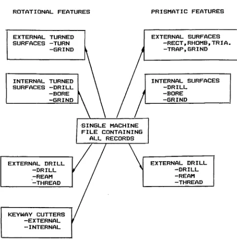
d e p e n d i n g on the s i z e of the problem. As a result, the
s i n g l e d a t a b a s e was divided into a number of operation
s p e c i f i c d a t a b a s e s as illust r a t e d in Fig u r e 5.5.
T h e m a c h i n e f i l e s w e r e divided in such a manner that
t h e c l a s s of o p e r a t i o n s in each of the f i l e s w a s s pecific
to a p a r t i c u l a r c l a s s of f e a t u r e s to be generated. By
s e p a r a t i n g the files, t h e search time was d r a s t i c a l l y
r e d u c e d and o n l y re l e v a n t r e c o r d s w e r e sea r c h e d for each
r e q u i r e d operation. S i n c e a m i c r o - c o m p u t e r based s y s t e m is
c o n s i d e r a b l y slower than a larger sys t e m the task of
s e a r c h i n g r e c o r d s can be several t i m e s longer than in
lar g e r c o m p u t e r system. A l s o a m i c r o - b a s e d s y s t e m may t ake
a c o n s i d e r a b l e amount of t i m e to c o m p u t e the same amount of
inform a t i o n as a mini or mainframe, thus maki n g the s y s t e m
n o n - e c o n o m i c a l .
C o n s i d e r i n g the speed at which the i nformation should
b e p r o v i d e d b y t h e s y s t e m t o t h e o perator it w a s n e c e s s a r y
to make c ertain a s s u m p t i o n s (as o u tlined in Section 4.3) to
r e d u c e t h e n u m b e r of c a l c u l a t i o n s performed. If many of the
B R E A K - U P O F M A C H I N E F I L E S
R O T A T I O N A L F E A T U R E S P R I S M A T I C F E A T U R E S
E X T E R N A L S U R F A C E S — R E C T ,R H O M B ,T R I A - T R A P , G R I N D
E X T E R N A L T U R N E D S U R F A C E S - T U R N
- G R I N D
I NTERNAL S U R F A C E S - D R I L L
- B O R E - G R I N D
E X T E R N A L D R I L L - D R I L L - R E A M - T H R E A D S I N G L E M A C H I N E
F I L E C O N T A I N I N G A L L R E C O R D S I N T E R N A L T U R N E D
S U R F A C E S - D R I L L - B O R E - G R I N D
E X T E R N A L D R I L L - D R I L L - R E A M - T H R E A D
K E Y W A Y C U T T E R S - E X T E R N A L - I N T E R N A L
T h e A b o v e B r e a k Up Of T h e M a c h i n e F i l e s A l l o w s
For M o r e R a p i d Re t r i e v a l Of I n f o r m a t i o n
b e t t e r off t o d e v e l o p p r o c e s s p l a n s m a n u a l l y w i t h o u t t h e
aid of a m i c r o - c o m p u t e r . T h r o u g h o u t t h e design, c a r e was
t a k e n t o m i n i m i z e t h e c o m p u t i n g and s e a r c h i n g t i m e r e q u i r e d
in o r d e r to m a k e a m i c r o - b a s e d s y s t e m j u s t i f i e d for u s e in
s m a l l e r m a c h i n e shops. T h e f i l e s t r u c t u r e u sed a l l o w e d for
r a p i d s e a r c h i n g and l o c a t i n g of s p e c i f i c i n f o r m a t i o n and
c o n t a i n e d t h e n e c e s s a r y i n f o r m a t i o n for m a c h i n e tool
selection. A m e t h o d w h i c h s ped up t h e s e a r c h p r o c e s s w a s to
c r e a t e r a n d o m a c c e s s m a c h i n e d a t a b a s e files. By c r e a t i n g
r a n d o m a c c e s s files, s p e c i f i c i n f o r m a t i o n can be r e a d for a
p a r t i c u l a r m a c h i n e tool w i t h o u t a sequential sea r c h of all
records.
T h e s p e c i f i c d e s c r i p t i o n of t h e m a c h i n e f i l e is d i v i d e d
i n t o t h r e e categories;
1. M a c h i n e C h a r a c t e r i s t i c s
2. P r o c e s s C h a r a c t e r i s t i c s
3. Tool C h a r a c t e r i s t i c s .
E a c h of t h e s e c a t e g o r i e s a r e u sed t o c r e a t e an
individual m a c h i n e record. A f l o w c h a r t and listing of t h e
p r o g r a m is c o n t a i n e d in A p p e n d i x B. T h e p r o g r a m was
d e v e l o p e d so t h e i n f o r m a t i o n on a p a r t i c u l a r m a c h i n e would
not h a v e to b e i n p u t t e d r e p e a t e d l y for each record. T h e
i n f o r m a t i o n w o u l d be i n p u t t e d o n c e and all r e c o r d s for that
m a c h i n e will h a v e a c c e s s t o t h e information. A sim i l a r
number of t o ols on the same machine. The specific
i nformation on each of t h e s e s e c t i o n s will be outlined in
the fol l o w i n g sections.
S . 1.1.1 M a c h i n e C h a r a c t e r i s t i c s
T h e first task is to input the general mac h i n e
c h a r a c t e r i s t i c s in the program. T h e information to be
inputted includes;
1. M a c h i n e number
2. M a c h i n e h o r s e power and
3. Number of o p e r a t i o n s which
can be p e r formed on the
machine.
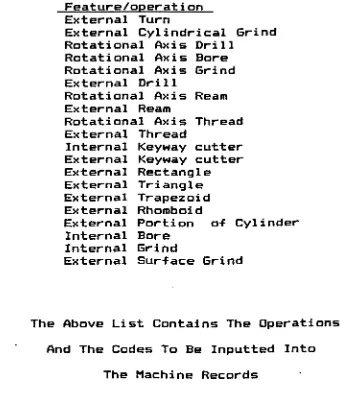
A c o m p l e t e listing of o p e r a t i o n s which are included in
the s y s t e m are listed in T a b l e 5.1. Along with each of the
o p e r a t i o n s in the table, is t h e operation code which will
be inputted in the next por t i o n of the m a c h i n e d escription
program. O n c e t h e above i n f o r m a t i o n h a s been inputted t h e
ope r a t o r must input t h e p r o c e s s characteristics.
5 . 1 . 1 . 2 P r o c e s s C h a r a c t e r i s t i c s
In t his section, a m o r e sp e c i f i c d escription of the
F e a t u r e s And C o d e s For A l t e r a t i v e O p e r a t i o n s
F e a t u r e / o p e r a t i on C o d e
1. External T u r n 1
2. E xternal C y l i n d r i c a l G r i n d 2
3. Ro t a t i o n a l A x i s Drill 3
4. R o t a t i o n a l A x i s B o r e 5
5- Ro t a t i o n a l A x i s G r i n d 6
6- External Drill 8
7. R o t a tional A x i s R e a m 4
8. External R e a m 9
9. Ro t a t i o n a l A x i s T h r e a d 7
10. External T h r e a d 10
11. Internal K e y w a y c u t t e r 13
12. External K e y w a y c u t t e r 14
13. External R e c t a n g l e 15
14. External T r i a n g l e 16
15. External T r a p e z o i d 17
16. External R h o m b o i d 18
17. External P o r t i o n of C y l i n d e r 19
IB. Internal B o r e 11
19. Internal G r i n d 12
20. E xternal S u r f a c e G r i n d 20
T h e A b o v e L ist C o n t a i n s T h e O p e r a t i o n s
And T h e C o d e s T o Be Inputted Into
T h e M a c h i n e R e c o r d s