Flow-induced Vibration Scale Testing of ACP100 Reactor Internals
Lixia Gao1, Jie Yang1, Tiancai Tan1, Danping Yu1, Jianzhong Ma1
1
Nuclear Power Institute of China, CN
ABSTRACT
ACP100 is a small modular reactor which is a new type Integral Pressurized Water Reactor with the third generation of nuclear power technology level. ACP100 reactor doesn’t have the primary coolant pipes because the primary pumps are installed at pump junctions of pressure vessel, and the steam generators are installed in pressure vessel. The internals structures are different from the traditional PWRs. The 1:2 scale testing of ACP100 reactor internals have been done. The vibration responses of major internal components have been measured. The preliminary FIV fatigue evaluations of major internal components have been done according to test results. The major components have been checked after 50 hours endurance test at rated operating condition.
INTRODUCTION
Flow-induced vibration (FIV) of reactor structure is an important dynamics problem. Reactor internals are classified 8 types, that include prototype, valid prototype, conditional prototype, non-prototype (category I), non-prototype (category II), limited valid prototype, non-prototype (category III), non-prototype (category IV) in ‘R.G. 1.20 Comprehensive Vibration Assessment Program for Reactor Internals during Preoperational and Initial Startup Testing’ of U.S.A NRC. The FIV assessment of different internal types are different. The internal structures are very complex, and FIV is a fluid-structure interaction vibration problem, so FIV test method is the most feasible. Test methods are included scale testing and in-situ measurement. The object of scale testing that done at room temperature and atmospheric pressure is to verify the design of FIV is reasonable or not and provide the for design modification. In-situ measurement is done at hot test run that verifies the correctness and rationality of the theoretical analysis and scale testing.
ACP100 is a small modular reactor which is a new type Integral Pressurized Water Reactor (PWR) with the third generation of nuclear power technology level. ACP100 reactor doesn’t have the primary coolant pipes because the primary pumps are installed at pump junctions of pressure vessel, and the steam generators are installed in pressure vessel. The internals structures of ACP100 are different from the traditional PWRs very much, so the FIV assessment is the most one of safety check. FIV scale testing of ACP100 reactor internals is discussed in this paper.
STRUCTURE SUMMERY
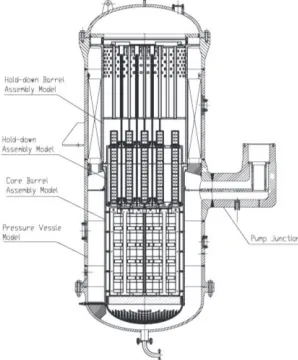
ACP100 is an integral reactor, the main components are included pressure vessel, core barrel assembly, hold-down barrel assembly, hold-down assembly, flow divider structures, primary pumps and steam generators. Primary pumps are installed at pump junctions of pressure vessel, and steam generators are installed in pressure vessel.
The structure characteristics of ACP100 compare with traditional PWRs are as follows:
• The length of core barrel is shortened.
• The traditional upper core support structures take the place of down barrel assembly and hold-down assembly.
• Flow dividers which include two structures are new components for separating in-out coolant. One is a flow divider annular plate that is welded at inner wall of pressure vessel. Another is a flow divider plate that is welded in pump junction.
The 1:2 scale mock-up is been designed and manufactured. Key components must be strictly designed according to 1:2 geometry similarity ratio (see Figure 1).
Figure 1. 1:2 Scale mock-up
FLOW LOOP
Flow loop can deliver water flows up to 1500m3/h×2, and head of pump is 60mH2O. The loop flow diagram is shown in Figure 2.
Figure 2. Test loop flow diagram
TEST CONTENTS
Test contents are as follows:
• Model tests (in air and in water).
• FIV tests at 1346m3/h (80% rated flow), 1683m3/h (100% rated flow) and 2020m3/h (120% rated flow).
INSTUMENTATIOIN
Accelerometers were used for model tests. Accelerometers, strain gauges, electric eddy current sensors and pressure sensors were use to measure the vibration response of internals. Core barrel flange root was instrumented with six strain gauges around circumference. Core barrel was instrumented with thirty pressure sensors and two electric eddy current sensors to measure the fluctuating pressures outside wall and displacements of barrel. Two strain gauges were instrumented at flange root of hold-down assembly. Four strain gauges were instrumented at flange root of hold-down barrel assembly, and six pressure sensors were instrumented at hold-down barrel to measure the fluctuating pressure inside wall.
RESULTS AND DISCUSSION
Model Test Results and Discussion
Model test results of core barrel assembly, hold-down assembly and hold-down barrel assembly are given in Table 1-Table 3. Compared with the measured and calculated frequencies of core barrel assembly and hold-down barrel assembly, the relative deviation was within 20%. Because of the effect of added mass of water, the structure’s natural frequencies in water were obviously smaller than that in air. But there was an very interesting phenomenon about hold-down barrel assembly which frequency (n=2) in water was larger than in air.
Core barrel cylinder and hold-down barrel cylinder is concentric cylindrical shell, and hold-down barrel is inside core barrel. The clearance between out-wall of hold-down barrel and in-wall of core barrel is 3.75mm, that is very small. The effect of small water clearance for natural frequencies is boring. The traditional added mass method isn’t applicative any more. The effect of small water clearance between concentric cylindrical shell need deeply study in future.
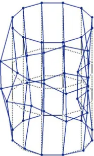
The mode shapes in air and in water were same, which were given in Figure 3-Figure 9.
Table 1: Model test results of core barrel assembly
Conditions Types of Frequency Measured values
Calculated values
Relative Deviation
In air [Hz]
Beam frequencies 86.2 81.4 5.6%
Shell frequencies
m=1, n=2 202.9 241.4 -19.0%
m=1, n=3 178.5 190.1 -6.5%
In water [Hz]
Beam frequencies 39.5 44.4 -12.4%
Shell frequencies
m=1, n=2 118.2 119.7 -1.3%
m=1, n=3 127 101.5 20.1%
Table 2: Model test results of hold-down assembly
Conditions Types of Frequency Measured values
Calculated values
Relative Deviation
In air [Hz] Shell frequencies
m=1, n=2
354.2
358.9
-1.3%
m=1, n=3
456.5
376.5
17.5%
In water[Hz]
Shell frequencies
Table 3 Model test results of hold-down barrel assembly
Conditions Types of Frequency Measured values
Calculated values
Relative Deviation
In air [Hz] Shell frequencies
m=1, n=2
382.3
396.2
-3.6%
m=1, n=3
327.4
357.7
-9.3%
In water[Hz]
Shell
frequencies
m=1, n=2
297.8
üü
üü
Figure 3. Beam mode shape of core barrel assembly
Figure 4. Shell mode shape of core barrel assembly (m=1 n=2)
Figure 6. Shell mode shape of hold-down assembly (m=1 n=2)
Figure 7. Shell mode shape of hold-down assembly (m=1 n=3)
Figure 8. Shell mode shape of hold-down barrel assembly (m=1 n=2)
FIV Test Results and Discussion
Time Domain Results and Discussion
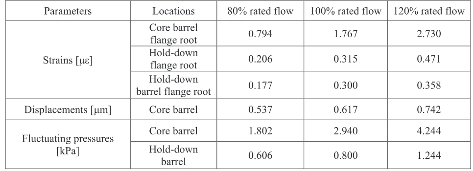
The maximum root mean square (RMS) are given in Table 4. Fluctuating pressures were FIV loads. Strains and displacements were FIV response.
The characteristic of FIV loads of ACP100 reactor internals were as follows:
• The fluctuating pressures were very small because of the low coolant velocities.
• The fluctuating pressures increased with the increment of flow velocities.
• The fluctuating pressures near to inlet were maximal, and they reduced along core barrel axial direction. The values were more small far away from inlet.
The characteristics of FIV response of ACP100 reactor internals are as follows:
g Strain response results were very small, and the core barrel flange root strains were the maximal. All strain values increased with the increment of flow velocities.
g Core barrel displacements were very small too.
Table 4: Maximum (RMS) of vibration responses
Parameters Locations 80% rated flow 100% rated flow 120% rated flow
Strains [με]
Core barrel
flange root 0.794 1.767 2.730
Hold-down
flange root 0.206 0.315 0.471
Hold-down
barrel flange root 0.177 0.300 0.358
Displacements [μm] Core barrel 0.537 0.617 0.742
Fluctuating pressures [kPa]
Core barrel 1.802 2.940 4.244
Hold-down
barrel 0.606 0.800 1.244
Frequency Domain Results and Discussion
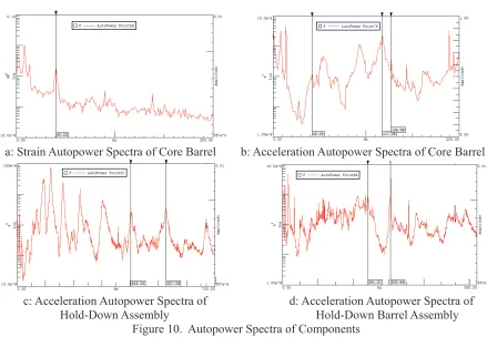
Strain autopower spectrum of core barrel and acceleration autopower spectra of core barrel, hold-down assembly and hold-down barrel assembly are shown in Figure 10. The structural frequencies could be identified in Figure 10. The frequencies were given in Table 5.
Table 5: Frequencies of Key Components
Types of Frequency
Core Barrel
Hold-Down Assembly
Hold-Down Barrel
Assembly
FIV
Frequencies
Natural
Frequencies
FIV
Frequencies
Natural
Frequencies
FIV
Frequencies
Natural
Frequencies
Beam frequencies[Hz] 40.22/42.04 39.50/42.40
üü
üü
üü
üü
Shell
frequencies
[Hz]
m=1,n=2
117.24
118.20
527.08
527.10
305.44
297.80
a: Strain Autopower Spectra of Core Barrel b: Acceleration Autopower Spectra of Core Barrel
c: Acceleration Autopower Spectra of d: Acceleration Autopower Spectra of Hold-Down Assembly Hold-Down Barrel Assembly
Figure 10. Autopower Spectra of Components
Fluctuating pressure autopower spectra of core barrel and hold-down barrel are shown in Figure 11. The energies of fluctuating pressure autopower spectra caused by turbulence were located in the low
frequency bands, and they decayed very fast with the increment of frequencies. The tendencies of fluctuating pressure were in accord with former FIV results.
a: Core Barrel b:
Hold-Down Barrel Assembly Figure 11. Fluctuating Pressure Autopower SpectraPrototype Results Derivation and Fatigue Analyses
According to the maximum strain of structure, we could derive the maximum stress. The maximum stress was 1.567MPa, which was located at core barrel flange root. The maximum stress was far lower than high-cycle fatigue allowable stress of material.
Endurance Test Results
The first order beam frequency of core barrel in water was the most minimum, which was the basis of endurance test. The vibration numbers of main internal structure must exceed 7×10⁶, so the endurance test time was 50 hours.
Visual inspection of internal structures was done after endurance test. The internals structures were no obvious deformation, and fastener connections didn’t loosen, and there were no obvious wear and tear.
CONCLUSIONS
The conclusions of 1:2 scale mock-up FIV test of ACP100 internals were as follows:
g The maximum stresses of internals were far lower than high-cycle fatigue allowable stress of material, so design of ACP100 internals were safe on FIV.
g 50 hours endurance test at100% rated flow was done, and the vibration numbers exceed 7×10⁶. Visual inspection after test was done, and internal structures were no obvious deformation, wear and tear.
g The dynamical characteristic of small water clearance concentric cylindrical shell should be further studied in future.
REFERENCES
ASME Boiler&Pressure Vessel Code, ASME Boiler&Pressure Vessel Committee Subcommittee on Nuclear Power, July 1, 2004.