Study of Screw Compressor Package and
Design of Throttle Lever Action
Nataraja M1, Kumarswamy R2, Manjunath K3, Shivakumar S4.
Assistant Professor, Department of Mechanical Engineering, Sir M Visvesvarya Institute of Technology, Bangalore,
Karnataka, India1
Assistant Professor, Department of Mechanical Engineering, Sir M Visvesvarya Institute of Technology, Bangalore,
Karnataka, India2
Assistant Professor, Department of Mechanical Engineering, SEA College of Engg.. & Technology, Bangalore,
Karnataka, India3
Assistant Professor, Department of Mechanical Engineering, Sir M Visvesvarya Institute of Technology, Bangalore,
Karnataka, India4
ABSTRACT: This paper deals with the complete study of the working of the rotary screw type compressor – PA 415 ATC PLUS. It is two stage compressor driven by a 415BHP, 6- cylinder engine pressurizes air and stores it in the separator tank. The current regulation of the entire package is with the help of pneumatic actuator system. Although, this system has a quick reaction time, it is not very accurate. Due to this, RPM of the engine cannot be regulated. Due to these reasons, the current system is to be replaced by an electronic actuator system which helps in RPM regulation and improves the efficiency of the mechanical engine.
KEYWORDS: Compressor, Engine, Pressure.
I. INTRODUCTION
An air compressor is a device that converts power using an electric motor, diesel or gasoline engine, etc into potential energy stored in pressurized air. By one of several methods, an air compressor forces more and more air into the storage tank, increasing the pressure. When tank pressure reaches its upper limit, the air compressor shuts off. The compressed air, then is held in the tank until called into use. The energy contained in the compressed air can be used for a variety of applications utilizing the kinetic energy of the air as it is released and the tank depressurizes. When tank pressure reaches its lower limit, the air compressor turns on again and re-pressurizes the tank. The types of compressors: An air compressor is broadly classified as: Rotary screw compressor, Axial compressor
Axial compressor:An axial compressor is a compressor that can continuously pressurises the gases. It is a rotating air foil based compressor in which the gas or working fluid principally flows parallel to the axis of rotation or axially. This differs from other rotating compressors such as centrifugal compressor, axial-centrifugal compressors and mixed- flow compressors where the fluid flow will include a ‘radial component’ through the compressor. The energy level of the fluid increases as it flows through the compressor due to the action of rotor blades which exert a torque on the fluid. The stationary blades slow the flow, converting the circumferential component of flow into pressure. Compressor are typically driven by an electric motor or a steam or a gas turbine.
Pneumatic Regulation System:The air compressor used at Doosan Bobcat India Pvt. Ltd uses the pneumatic regulation system to control the various operation of the compressor. Although the pnuematic regulation system has a quick response time, it lacks accuracy and thus the efficiency of the whole system is reduced. Also, engine speed regulation is also difficult with the current pneumatic regulation system. Due to the above reasons, the current pneumatic regulation system is to be replaced by a more efficient electronic regulation system.
II. RELATED WORK
Nikhil M Patel, PROF.B.B.Shah and Dr Raman, in their technical paper titled “ Design and Analysis for Screw Compressor[1]” say that screw compressor is a positive displacement machine used for compressing air to moderate pressures. Screw compressors are used in various industries due to their relatively high rotational speeds compared to other types of positive displacement machines which make them compact, their ability to maintain high efficiencies over a wide range of operating pressures and flow rates and their long service life and high reliability. They conclude by saying the performance of process air screw compressors is highly dependent on their root profiles and clearance distribution reduction in the number of edges and optimizing geometry increases its efficiency.
Professor N. Stosic, Prfessor Ian K. Smith, Professor A. Kovacevic and Dr. E.Mujic in their research paper titled “Three Decades of Modern Practice in Screw Compressors[2]” mainly talk about the evolution in working and design of screw compressors over the past 30 years. Over the past 3 decades, reciprocating compressors have been replaced by screw type compressors mainly due to improved rotar profiles, which have reduced internal leakage. Screw compressors are widely used for commercial purposes. Although there is a rapid growth in screw compressors usage, the scientific basis of their design is still limited. Recent developments in screw compressors such as rotar configuration, rotar sealing line length and blow-hole area, rotor proportions, rotar wrap angle, compressor bearings, rotar clearance distribution , thermal expansion of rotars and housing and optimization of the compression process are discussed in this paper.
“Optimization Of Air Compressor Motor Speed for Reducing Power Consumption[3]”is a research paper authored by Amit Bahekar and Dr. Sanjeev Yadavwhich provides insights into saving high amounts of energy(fuel) by controlling the engine speed with respective air pressure demands. According to the required air pressure, the motor is maintained at optimum speed with the help of a variable speed drive which is programmed by programmed microcontroller. In addition to the speed reduction, on/off control has been introduced where the compressor turns on and begins to add compressed air to the system when the system pressure falls to the lower activation pressure. The compressor is turned off once the system pressure reaches the upper activation pressure.
Rohit Burt and Sachin Mestry in their journal paper titled “Four Bar Linkage Synthesis and Design for Generation of Five Coupler Positions [4]” say Four-bar planar mechanisms have wide applications in industry and thus receive more attention from machinery design researchers. A mechanical system is made up of several components, which can be divided into two major groups namely links and joints. This work presents an analytical approach depends on forming mathematical model for mechanism position incorporating five coupler positions. A four-bar chain is the most fundamental of the plane kinematic chains. It is a much-preferred mechanical device for the mechanization and control of motion due to its simplicity and versatility. A four-bar linkage is a versatile mechanism that is widely used in machines to transmit motion or to provide mechanical advantage. In this paper, synthesis of four bar mechanism is done for five coupler position. The approach is very accurate in synthesizing 4-bar planer mechanism for different positions of its coupler. It is found that the coupler traces exactly the desired positions with transmission angles not more than 29.7% of the optimum value of 900. There is large deviation in the fifth mechanism position for five coupler positions because its transmission angle was not included in the model equations.
“Maintenance of an Air Compressor used in Quarries [6]”. Authored by Ogundele O.J., Osiyoku D.A. Braimoh. J and Yusuf. I talk about the classification of air compressors based on how pressure is developed in the fluid. Also, they talk about the materials, selection of compressor, and determination of compressor capacity and determination of compressor efficiency for a particular process.
“ Turbocharging of diesel Engine for improved performance and Exhaust Emission: Areview [7]”, is a paper by Mohd
Muqeem, Dr. Muktar Ahmad and Dr. A.F. Sherwani in which, they talk about the advantages of using a turbo charger in a diesel engine. : Turbochargers are used throughout the automotive industry to enhance the output of an internal combustion engine without increasing the cylinder capacity. The application of such a mechanical device enables automotive manufactures to adopt smaller displacement engines, commonly known as engine downsizing. Turbocharges were often used to increase the potential of an already powerful IC engine, e.g. those used in motorsport. The emphasis and “greener” road vehicles. It is because of these reasons that turbochargers are now becoming much more popular in automotive industry applications.
III.STUDYOFCURRENTSYSTEM
PA 416 ATC plus:PA stands for prospair series of the machine which is currently being used for the project study and experimentation. 415 represent the horsepower of that engine. ATC represents that this machine has automatic temperature control. An air compressor is a device that converts power (using on electric motor. Diesel or gasoline engine, etc.) Into potential energy stored in pressurized air (i.e., compressed air). By one several methods. An air compressor forces more and more air into a storage tank, increasing the pressure. This compressor package is controlled by regulation system major elements they are throttle lever and piston cylinder assembly. These elements are used to control the engine rpm.
Engine: The engine is an inline six cylinder, compression ignition diesel engine which produces 415 horsepower at 1900 rpm. This is Cummins fan drive that is for automatic temperature control. The specification of this engine is as follows:
Compressor/ Airend:A screw compressor is a type of rotary compressor which compresses air due to screw action. The main advantages of using this compressor are that it can supply compressor air continuously with minimum fluctuation in delivery pressure. Compressor used in the machine PA 415 ATC PLUS is a two-stage rotary vane Compressor. The two storage are: 1. Low Pressure storage, 2. High pressure storage: In the First storage i.e., low pressure storage. Air from the atmosphere is sucked into the compressor along with all. Compressed air is then pushed towards the high-pressure storage where it is compressed even further. This high-high-pressure mixture of air and oil is passed onto the separator tank through the bottle plate which deflects it at an angle. With the help of centrifugal action, as oil is denser than air. It settles down at the bottom at the separate tank and is recycled. This air at high pressure is used through the service line.
Valves used in regulation system: Anti-rumble value: Compressor damage. A typical anti-rumble system to prevent compressor damages. A typical anti-rumble system includes a recirculation path for discharges air back through the rotors while the unloaded value is shut, in an anti-rumble system. Air is re-circulated from on oil/air separator tank on the discharges of the compressor back to the compressor inlet.
Pressure Regulator value (PRV): A pressure regulator is a control valve that reduces the input pressure of a fluid to a desired value at its output. Regulators are used for gasses and liquids and can be an integral device with output pressure setting. A restrictor and a sensor controller and flow valve. A pressure regulation primary function is to match the flow of gas through the regulator to the demand for placed upon it. This is maintaining a contact output pressure. Regulator is often used to adjust the pressure coming out of an air receiver (tank) to match what is needed for the task. Often, when one large compressed air for multiple uses often referred to as “shop air” if built as a permanent installation of pipes throughout a building) additional regulators will be used to ensure that each separate tool are function receives the approximate pressure it needs. This is important because some air tools, or materials. If the load flow decreases, then the regulator flow must increase in order to keep the controlled pressure from decreasing due to a shortage of gas in the pressure system.
Air Intake Valve: An Air Intake Valve is a valve can be used for isolating or regulating flow. The closing mechanism takes the form at a disk. Operation is similar to that at a ball valve. Which allows for quick shut off Butterfly Valves are generally favored because they are lower in cost to other valve designed as well as being lighter in weight? Meaningless support is required. The disc is positioned in the centre of the pipe: passing through the disc is rod connected to an actuator on the outside of valve rotating. The actuator turns the disc either parallel or perpendicular to the flow. Unlike a ball valve is used to regulate the air flow into the air and (compressor) according to the demands at the service line. This from the pneumatic regulation system. Temperature bypass valve with modulate fluid temperature by shifting return line flow through the cooler or bypassing it directly to the reserve. When the temperature of the compressor liquid reaches around 900C-compressor liquid is passed onto the oil is cooled and is again passed through the temperature bypass valve. If the temperature of the liquid is less than 900C, it is passed onto the reservoir. Else it is again sent for cooling to the oil cooler.
Start-Run valve: When the output is required, compressor needs to be termed into RUN mode. It disconnects the re-circulation of air within the system and activates the regulation system which will sense the output requirement and accordingly regulates the engine speed and opening of air intake valve as well.
IV.EXPERIMENTAL RESULTS
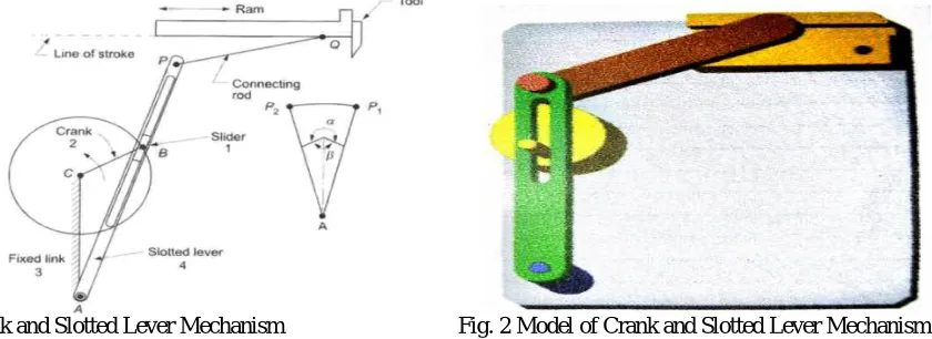
Crank and slotted level slotted level quick return motion mechanism: it is an inversion of quick return mechanism where connecting rod is fixed. It finds application in shaping machine. Slotting machine. Rotary internal combustion engine. In this mechanism link corresponding to the connecting rod(AC) is fixed. The fig below) revolves about the fixed centre C.A slides along the slotting levels oscillate about the provided point A. A short link PO transmits the motion from AP to the arm which reciprocates with the tool along the line of stroke. We see that the angle made by the forward or cutting stroke is greater than the angle a describe by the return stroke. Hence the name quick returns mechanism.
Design throttle lever action using crank and slotted lever mechanism: this design replicates the throttle lever action and helps in measuring the precise linear movement corresponding the angular movement Mechanism Implemented:Crank and slotted lever quick return mechanism; Calculation:Length of lever=102 90mm; Angular movement=160; To find: Corresponding linear movement:Sin ( ) = (opposite side)/ (hypotenuse); Sin ( ) = x/102.96=28.66mm: Length of lever=102.96mm; Required linear movement=28.66mm; Required angular movement=160; Vertical dist. From fixed point o=76.4625mm: Sin ( ) = (radius of com)/ (vertical dist. From fixed point o); Sin ( ) = r/76.4625= 10.64mm. Ports Designed and their Geometry:
Slotted lever: This lever replicates the throttle lever action; it will have an angular movement of 16 degrees. Crank and slotted lever mechanism is used for the angular movement.
Connecting lever:This element helps in giving the inputs to the main lever movement, this linked with the main lever movement of 28mm.
Slide rack: This element houses the slider linked with the main lever having a linear movement of 28mm. A scale is fixed to measure the exact linear movement to the corresponding angular movement of the main lever.
Cam Support:The cam support is used to connect the rotating cam with the flatform. This member will also allow for the free degree of freedom. Thus, the ratating cam can rotate only about its axis.
Pin:The main use of the pin is to connect the slotted lever with connecting lever to the main lever.
Platform:All the parts of the prototype are mounted on top of the platform. The platform acts as a support structure and thus supports all the parts of the prototype.
Fig. 1 Crank and Slotted Lever Mechanism Fig. 2 Model of Crank and Slotted Lever Mechanism
V. CONCLUSION
The study on the screw compressor package and its regulation system found the drawbacks and the inefficiency in operation of the current pneumatic regulation system used to regulate the speed of the engine. The prototype designed based on the principle of crank and slotted quick return mechanism replicating the action of the throttle lever of the engine coupled with compressor provides precise w2hich in turn improves the overall efficiency of the compressor packages. In the conversion of the current regulation system to electronic actuator. Precise movement of the throttle lever is a very important factor. By converting the current pneumatic regulation system to electronic actuator system. The efficiency of the compressor packages increases marginally.
REFERENCES
[1] Design And Analyses for screw compressor, Nikhil M, Patel, Proof, B.B. Shah, Dr. A. Roman ISSN 0975-668x. Volume 02, issue02, page511-514, November 2012.
[2] Three Decades of modern Practice in Screw Compressors, Prof .N. Stosic. Prof. Ian K. Smith, Prof .A.Kovacevic,Dr.E.Mujic, International Compressor engeneering Conference at Parude,July 12 2010.
[3] Optimization Of Air Compressor Motor Speed for Reducing Power Consumption,Amit Bahekar , Dr. Sanjeev Yadav, ISSN 2349-2163,Volume 1, Issue 6, July 2014.
[4] Four bar linkage synthesis and design for generation of five coupler positions ,rohit burte,sachin mestry, ISSN 2319-8753, Volume 5, Issue 9, september 2016.
[5] Sensitivity of contact electronic throttle control sensor to control system variation ,Robert d. Garrick, , ISSN 2006-01-0763,Volume 1, 200 SAE World Congress, April 2006.
[6] Maintainance of air compressors used in quarries,Ogundele O.J. Osiyoku D.A.,Braimoh j. yusuf I., , ISSN 2321-435X,pages 621-627, June 2014. [7] Turbocharging of Diesel Engine for Improving Performance and Exhaust Emissions: A Review, Mohd Muqeem, Dr. Mukhtar Ahmad, Dr.
A.F.Sherwani, , ISSN 2278-1674,Volume 12, Issue 04,Page 22-29, July 2015. [8] Screw Compressors:Misconception or Reality, Trent Bruce, Page 1-8.
[9] Research of Intelligent Control of Air Compressor at Constant Pressure, Gongfa Li, Jianyi Kong, Gouzhang jaing, Liangxi Xie, , ISSN 1147-1154, Volume 7, Issue 5, May 2012.
[10] Dry Screw Compressor Performance and Application Range, Jurgen Wennemar, Pages 149-156. [11] Compressor Selection and Sizing, A.L.Ling, Viska Mulyandasari, ,Volume 1, pages51- 62, March 2008.
[12] Test of New Screw Compressor with High Delivery Pressure, Marian Nitulescu, Cristian Slujitoru, Valentin Petresc, , ISSN 2066-8201,Volume 04, Issue 04,Pages 151-159, April 2012.