Vehicle Locking Using Radio Frequency
Identification with Theft Intimation and
Smart Tracking System
Manu Poduval
1, Nitish Pokharkar
2, Anirudha Punekar
3, Mrs. S. D. Borde
4Student, Dept. of Electronics and Telecommunication Engg., PES‟s Modern College of Engg, Pune, India1 Student, Dept. of Electronics and Telecommunication Engg., PES‟s Modern College of Engg, Pune, India2
Student, Dept. of Electronics and Telecommunication Engg., PES‟s Modern College of Engg, Pune, India3 Asst. Professor, Dept. of Electronics and Telecommunication Engg., PES‟s Modern College of Engg, Pune, India4
ABSTRACT
:
This paper presents the use of Radio Frequency Identification for locking the vehicle; along with vehicletheft intimation and smart tracking system. The present vehicle locking systems consists of; mechanical lock and key architecture or Remote Keyless Entry (RKE) architecture. The vehicle intruders can easily gain the access of the vehicle by duplicating keys, breaking mechanical locks and use radio frequency receivers with appropriate decryption algorithms in case of Remote Keyless Entry (RKE) architecture. Moreover, there isn‟t any provision for remotely communicating with the vehicle for tracing. The proposed system consists of using Unique Radio Frequency Identification cards along with password authorization for locking the vehicle. The driving license number issued by RTO‟s can be used for Unique Radio Frequency Identification along with password verification to unlock the vehicle and its ignition. Thus protecting the vehicle from intruders. Perhaps, this will also make the use of license mandatory to drive the vehicle. This project also involves a provision for theft intimation to the owner of the vehicle in the form of a call from the GSM module fixed in the vehicle. As soon as, the intruder will open the bonnet of the vehicle to start the ignition; which otherwise is not possible; the bonnet switch is open circuited and a call is initiated to the owners cellphone and GPS co-ordinates are continuously sent as SMS. Thus, vehicle‟s route can be easily traced on the Google maps.
KEYWORDS: AT- commands, Global Positioning System (GPS), GSM, Radio Frequency Identification (RFID)
I. INTRODUCTION
Fig.1.Table showing the survey of the number of vehicles stolen and recovered
II. PROPOSEDSYSTEM
Proposed system consists of integration of different technologies to enhance the vehicle security. This system also opens a new horizon for remotely communicating with the vehicle.
Fig.2.Block diagram of the proposed system
A. UNIQUE RFID CARD (LICENSE CARD) AND RFID CARD READER
When the RFID Card Reader is active and a valid RFID transponder tag is placed within range of the activated reader, the unique ID will be transmitted as a 12-byte printable ASCII string serially to the host microcontroller. This 12-byte code is a unique code which we propose to use as the license number of the owner so that the vehicle can be accessed only by the owner, enhancing the security of the vehicle and making the license compulsory to drive.
MICROCONTROLLO
ER
UNIT
LCD
RFID
READER
IGNITION CONTROL
UNIT
GPS UNIT
GSM UNIT
KEYPAD
UNIQUE
RFID
CARD (LICENSE
CARD)
Band Regulations Range Data speed Remarks 120–150 kHz
(LF) Unregulated 10 cm Low
Animal identification, factory data collection
13.56 MHz (HF)
ISM
band worldwide
10 cm - 1 m
Low to
moderate Smart cards 433 MHz
(UHF)
Short Range
Devices 1–100 m Moderate Defence applications, with active tags 865-868 MHz
(Europe) 902-928 MHz (North America) UHF
ISM band 1–12 m Moderate to
high EAN, various standards
2450-5800 MHz
(microwave) ISM band 1–2 m High 802.11 WLAN, Bluetooth standards 3.1–10 GHz
(microwave) Ultra wide band to 200 m High
requires semi-active or active tags
Fig.3. RFID frequency bands
According to the data available in the table above the RFID cards in ISM band or unregulated band can be used for this application.
B. MICROCONTROLLER UNIT
Microcontroller unit forms the heart of the system. This unit is responsible for accepting the unique 12-bit RFID code from the RFID reader. The secret password can be entered through the keypad unit in the vehicle. This password is accepted by the microcontroller unit and verified for its authenticity. The Ignition Control Unit is activated only when the RFID code and password is exactly matched. If the intruder tries to open the bonnet of the vehicle by any means to turn on the vehicle; which otherwise is not possible; the bonnet switch goes active low and thus an interrupt signal is initiated and microcontroller sends an AT command “ATD” followed by the owner‟s cell phone number to GSM unit and thus a call is initiated. This helps in vehicle theft intimation. The microcontroller unit also retrieves the latitude and longitude co-ordinates from the GPS module fixed in the vehicle and the same are sent to the owner‟s cell phone number via SMS. By using GSM module in the vehicle unit, it is now possible to remotely communicate with the vehicle. Certain code words can be used to retrieve the information from the vehicle.
Code Word to be sent from owner‟s cell phone
Response sent to the message from the GSM unit in Vehicle
1.Get GPS co-ordinates Used to retrieve the Latitude and Longitude co-ordinates of the vehicle. 2.Change License and Password For multi-user compatibility.
Fig.4. Table showing Different codes and its function.
C. GSM AND GPS UNIT
Command Response Description
AT+CMGF= OK Specifies the input and output format of the short messages. 0 for PDU mode and 1 for
text mode.
AT+CMGS Sends a message.
AT+CMGR=* Reads a message. * is the number of the message.
ATD*********; ********* is the number to call.
Fig.5. AT commands used for GSM module
The National Marine Electronics Association (NMEA) has developed a specification that defines the interface between various pieces of marine electronic equipment. The standard permits marine electronics to send information to computers and to other marine equipment. GPS receiver communication is defined within this specification. Most computer programs that provide real time position information understand and expect data to be in NMEA format. This data includes the complete PVT (position, velocity, time) solution computed by the GPS receiver. The idea of NMEA is to send a line of data called a sentence that is totally self-contained and independent from other sentences. Each sentence begins with a '$' and ends with a carriage return/line feed sequence and can be no longer than 80 characters of visible text (plus the line terminators)..
GLL - Geographic Latitude and Longitude
$GPGLL,4916.45,N,12311.12,W,225444,A,*1D Where:
GLL Geographic position, Latitude and Longitude 4916.46,N Latitude 49 deg. 16.45 min. North
12311.12,W Longitude 123 deg. 11.12 min. West 225444 Fix taken at 22:54:44 UTC
A Data Active or V (void) *1D checksum data
D.VEHICLE IGNITION CONTROL UNIT
Vehicle ignition control unit consists of a relay. Relay is controlled by the microcontroller after the verification of RFID card and password. The spark plug which is used to ignite the fuel in the IC engine of the vehicle is powered only after the relay changes its state and the battery is connected to the spark plug after verification of the card andpassword.Therefore, vehicle cannot be started by the intruder and thus eventually enhancing the security of vehicle.
III.FLOWCHARTOFPROPOSEDSYSTEM
IV.RESULTS
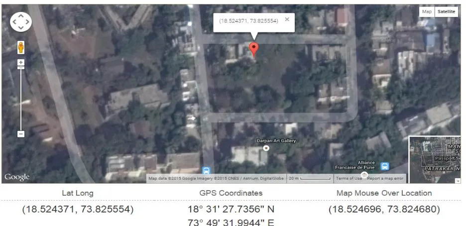
If vehicle is stolen we can trace it down using GSM and GPS modules. The coordinates received from GPS module can be plotted on Google maps and thus exact location of stolen vehicle will be known
Fig.10. GPS coordinates received and traced on Google Maps
Table I-Result Description
FIGURES DESCRIPTION
Fig a When system turned on it will tell to „scan license‟. Fig b When license is correct it will tell „you can proceed‟.
Fig c After that we have to enter vehicle security code; therefore it will ask to „enter password‟.
Fig d Password displayed. If password is correct then only vehicle ignition will be on. Fig e Shows password was incorrect.
Fig f Latitude and longitude coordinates received after code „Get Coordinates‟ was sent through user‟s mobile phone.
Fig 10 Shows coordinates traced on Google maps.
V.CONCLUSION
This approach described here presents a technique to prevent the vehicle theft by implementing Radio Frequency Identification and password verification. Since we are proposing to use driving license number for Radio Frequency identification; use of license will be mandatory while driving the vehicle. This system can also be used for tracking the vehicle by the owner at anytime from anywhere.
REFERENCES
1. Theodore S. Rappaport.Wireless Communication: Principles and Practice, Second edition, Pearson publication, Delhi. 2. Bill Glover, Himanshu Bhatt, RFID essentials, O'Reilly Media, Inc., 2006
3. Monk Simon ; Programming Arduino: Getting Started With Sketches;ISBN 978-0071784221.; 162 pages; 2011 4. "Using Atmel Studio for Arduino development". Megunolink.com.
5. T. Yunck, G. Lindal, C. Liu, The role of GPS in precise Earth observation Position Location and Navigation Symposium, December 1988, 251-258. 6. "Programming Arduino Getting Started with Sketches". McGraw-Hill. Nov 8, 2011.
7. "GSM Global system for Mobile Communications". 4G Americas.com.
8. Michel Mouly, Marie-Bernadette Pautet.The GSM System for Mobile Communications.
9. Redl , Sigmund M.; Weber, Matthias K.; Oliphant, Malcolm W (February 1995). An Introduction to GSM. Artech House. ISBN 978-0-89006-785-7 10. Weis, Stephen A. (2007), RFID (Radio Frequency Identification): Principles and Applications, MIT CSAIL
11. Miles, Stephen Bell (2011). RFID Technology and Applications. London: Cambridge University Press. pp. 6–8. 12. “Crime cases”. Indian Express.com.