Pounding Effect in Building
Pradeep Karanth1, Ravindranatha 2, Shivananda S.M3, Suresh H.L 4
Post Graduate Student, Dept. of Structural Engineering, Manipal Institute of Technology, Karnataka, India1 Assistant Professor (Selection Grade), Dept. of Civil Engineering, Manipal Institute of Technology, Karnataka, India2
Structural Engineer, Atkins India Pvt Ltd, Bangalore, Karnataka, India3
Director, Structural Engineer, CIVIL Technologies (India) Pvt Ltd, Bangalore, Karnataka, India4
ABSTRACT: Collision of two building which are of different dynamic characteristics is called as seismic pounding. The main reason for pounding is insufficient separation gap between the buildings. Pounding can be prevented by providing safe separation gap, but required gap is not possible in metropolitan cities. This study covers the effect of structural pounding on two building are of different structural system, in order to observe seismic pounding Time History analysis is carried out. This study also covers the prevention techniques of pounding by using introduction of RC wall and its optimization is proposed as possible mitigation techniques for pounding.
KEYWORDS: Seismic Pounding, Earthquake, SAP 2000, Flat slab, Reinforced Concrete (RC) wall.
I. INTRODUCTION
The Seismic pounding is simply known as collision or hammering of two buildings which are adjacent to each other having different dynamic characteristics. The main reason for the seismic pounding is a lack of separation gap in between the adjacent buildings. Most of the time pounding between the structures is commonly observed in the old buildings that were constructed before the earthquake resistant design principles came into the picture. Even though many present codes specify a minimum seismic gap, it still fails to include the effect of all other parameters that effect the structural deformation. The simplest and effective way for pounding mitigation and reducing damage due to pounding is to provide enough separation gap, but it is sometimes difficult to be implemented due to the high cost of land.
Pounding damage was assessed during the 1985 Mexico earthquake, the 1988 Sequenay earthquake in Canada, the 1992 Cairo earthquake, and 1944 Elcentro earthquake. Pounding of adjacent buildings could have worse damage as adjacent buildings with different dynamic characteristics which vibrate out of phase and there is insufficient separation distance (Abdel and Shehata, 2006 [1]). Previous seismic codes couldn’t give fixed guidelines to prevent pounding, due to economic considerations, especially in the metropolitan cities; there are many buildings worldwide which are already built extremely close to each another, that could suffer pounding damage in forthcoming earthquakes. A large separation is not feasible f r o m both technical and economical point of views (A Hameed et.al, 2 0 1 2 [ 2 ] ). The highly congested building system in many metropolitan cities constitutes a major apprehension for seismic pounding damage.
II. RELATED WORK
2.a) Shehata E.Abdel Raheem –“Seismic Pounding between Adjacent Building Structures(2006)”:
Studied building pounding response and proper seismic hazard mitigation practice for adjacent buildings. The effect of impact is studied using linear and nonlinear contact force model for different separation distances and is compared with nominal model without pounding consideration. The result of the study shows that pounding is a highly nonlinear phenomenon and that could result in significant structural damage, results in amplify the building displacement, acceleration shear demands will be much more than assumed values in design.
2.b) Amruta Sadanand Tapashetti et.al –“Prevention techniques of pounding between adjacent buildings(2014)”:
Carried out preventive measures of pounding between adjacent buildings. Different mitigation technique like Construction of new RC walls, cross bracing system and combined RC wall & bracing, dampers, combined system of RC wall and dampers and combined system of bracing and dampers with proper placement are proposed as possible prevention techniques for pounding between adjacent buildings . Stiffness of the buildings can be increased by adopting all this methods and all the prevention methods that are used in this study was found effective to counter act pounding between adjacent buildings.
III.METHODOLOGY
To observe pounding, a three-dimensional reinforced concrete moment resisting frame buildings is taken and analysed in SAP2000. For the analysis, eight (G+ 8) storey buildings consist of conventional beam column structural system adjacent to the six (G+6) storey building consists of flat slab system. All columns in the models are assumed to be fixed at the base. The height of all floors is 3.2 m. A slab of eight(G+8) storey are modelled as rigid diaphragm floor element of 150mm thickness and slab of six (G+6) storey are modelled as rigid diaphragm floor element of 150mm thickness and drop thickness is 200 mm and is designed as per to IS 456-2000. Live load on the floor is taken as 3kN/m2 and on the roof is 1.5kN/m2. Floor finish on the floor and weathering course on the roof is taken as 1kN/m2 respectively for the both the building. The seismic weight is calculated according to IS 1893-2002. The unit weight of concrete is taken as 25kN/m3.The grade of concrete for columns are M-25 and that of beams and slab are M-20. The building is analysed as special moment resisting frame considered to be situated in seismic zone IV having medium soil and proposed for residential use. These buildings are separated by expansion joint of 100mm. Both buildings are analysed in SAP2000 and are designed as per IS 456-2000. Both buildings are subjected to gravity and dynamic loads. To observe pounding, Time History Analysis is carried out by taking the data of Elcentro earthquake.
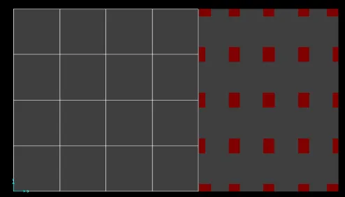
Building-A, Beam- column system consist of eight (G+8) storey has 4 bays in X and Y directions, having external columns size of 0.4x0.8 m2, whereas all internal column size of 0.55x1.0 m2 and beam size of 0.35x0.6 m2. The width of each bay in X direction is 4m, and that of in Y direction is 5m. Building-B, Flat slab system having six (G+6) storey has 4 bays in X and Y directions, the width of each bay in the X direction is 3m, in Y direction is 5m, having external column size of 0.3x0.75 m2, whereas all internal column size of 0.3x0.9 m2 and no beams in both directions (Flat slab structural system).Figure-1 shows the plan view of the conventional beam column system adjacent to the flat slab system both buildings are separated by 100 mm expansion joint both buildings are analysed in SAP2000.
IV.REQUIREDSEISMICSEPARATIONDISTANCETOAVOIDPOUNDING
Minimum safe separation gap to be provided between adjacent buildings to avoid pounding effect, which is equal to the peak displacement of the two potentially colliding building systems. For instance, according to the 2000 edition of the international building code and in many seismic design codes and guidelines worldwide, the minimum safe separation gap (Lopez Garcia 2004) is as follows:
S = √ (Q12 + Q22) is an SRSS (Square Root of the Sum of the Squares) Method S=Q1+Q2 is an Absolute Sum Method (ABS)
Where,
Q1= Peak displacement of building-A Q2= Peak displacement of building-B S = Separation distances
A. Required Seismic Separation Distance to Avoid Pounding
According to Bureau of Indian Standards clearly gives in its code IS 4326 that a safe separation distance is to be provided to prevent pounding between the building during an earthquake. The same is mentioned in following Table 1.
TABLE 1: The design seismic coefficient to be used in accordance with IS 1893:1984
Note: Minimum total gap shall be 25 mm. For any other values of αh, the gap width shall be determined accordingly.
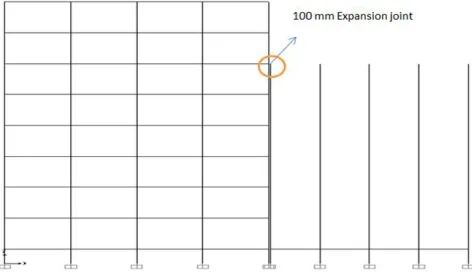
4.1. Beam column system adjacent to Flat slab system without any RC wall.
Figure-2: Elevation view of beam column system adjacent to flat slab system without any RC wall
and negative displacement of the G+6 storey, as we are going to consider worst condition due to its different dynamic characteristics.
Figure- 3: Time vs. displacement graph of beam column system adjacent to flat slab system at sixth -floor roof level without any RC wall.
Figure-3 shows time vs. displacement graph at the sixth-floor level, in this maximum positive displacement of G+8 storey building is 80.30 mm at 2.2 seconds and maximum negative displacement of G+6 storey building is 212.53 mm at 12.8 seconds. From the figure, it is noticed that maximum out of phase movement of both building is (80.30+212.53)-100= 192.83 mm which is greater than the given expansion joint, hence which is unable to accommodate this out of phase movement, and adjacent buildings will strike or collide each other.
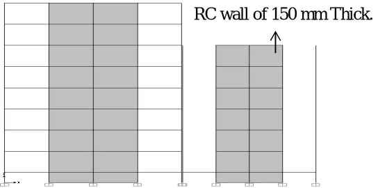
4.2 Introducing new RC wall to Increase the Stiffness:
In order reduce the lateral displacement and to increase the global stiffness of the building new RC walls are introduced as a preventive technique for the seismic pounding. RC wall shall be dowelled with the adjacent beams and columns to transfer lateral force safely to the ground
.
Figure- 4 Shows Beam column structure adjacent to flat slab system introduced with new RC walls of 150 mm thickness at the mid two panels of both the buildings in X direction to reduce lateral displacement of the buildings (Amruta Sadanand Tapashetti et.al, 2014[5]). In G+8storey building, RC wall is of 4 m in the X direction and in G+ 6 storey building RC wall is of 3m length in the X-direction. As we are interested in reducing the lateral displacement in X-direction were pounding going to occur. Time History Analysis is done by taking Elcentro Earthquake data, for which Time vs. Displacement graph plotted to observe the displacements of both the buildings at sixth-floor level.
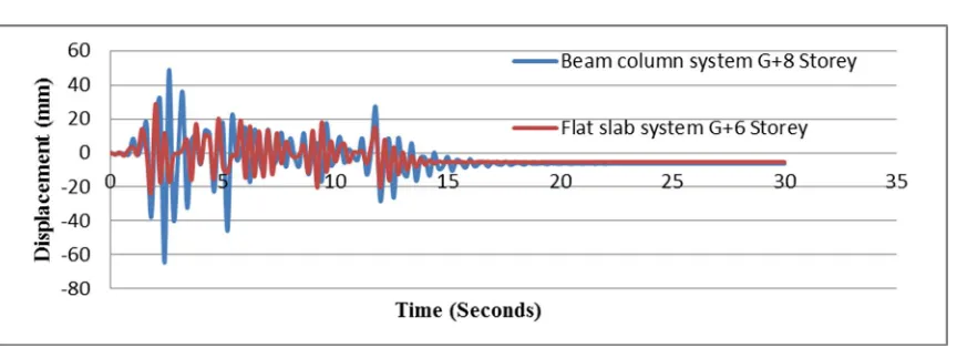
Figure 5: Time vs. displacement graph of beam column system adjacent to flat slab system at sixth -floor roof level with RC wall
Figure- 5 shows time vs. displacement graph at the sixth-floor level, in this Maximum Positive displacement of the eight-storey building is 21.61 mm and maximum negative displacement of six-storey is 37.61. Maximum out of phase movement is 21.61+37.61=59.23 mm, it is less than given expansion joint hence, no chance of pounding at any interval of time.
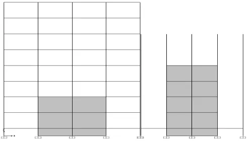
4.3 Optimization of RC wall length:
New RC walls are introduced to increase the global stiffness of the building, but in order to reduce the cost of construction the length of the RC walls are reduced. Figure 6 shows reduced length of RC wall In G+8 storey building, only two floors (25% total height of the building) are accommodated with new RC walls and in G+6 building 4 floors (67% total height of the building) are provided with new RC wall for which time history Analysis is done by taking Elcentro Earthquake data, for which time vs. Displacement graph plotted to observe the displacements of both the buildings at sixth-floor level.
Figure 7: Time vs. displacement graph for both the buildings after reducing the length of the RC wall
Figure-7 shows time vs. displacement graph at the sixth-floor level, in this Maximum Positive displacement of the G+8 storey at 6th floor is 48.71 mm at 2.6 second and maximum negative displacement of G+ 6 storey is 23.91mm at 1.8 seconds. It shows that Maximum out of phase movement is 48.71+23.91= 72.62 mm which is lesser than the expansion joint i.e. 100mm, hence no chance of pounding at any interval.
V. CONCLUSION
The stiffness of the flat slab system is less in comparison with beam – column system and hence design engineer have to give more importance while the design of such type structures.
The stiffness of the buildings can be increased by providing new RC wall so that lateral displacement can be reduced.
At the time of design, Design Engineer has to ensure that there will be no pounding between adjacent buildings.
It is better to leave set back/safe separation gap according to FEMA 273-1997 when the buildings are in early stage of design.
If buildings are old and are not in a stage to provide safe separation gap, then prevention measure should be taken by using retrofitting’s like introducing new RC wall, Cross bracings, Dampers etc...
All the prevention methods that are used in this study proved effective to prevent pounding between adjacent buildings.
REFERENCES
[1] Abdel R and E.Shehata “Seismic Pounding between Adjacent Building Structures” Electronic Journal of Structural Engineering, Vol -VI PP .66-74 ,2006.
[2] A. Hameed, M. Saleem, A.U. Qazi, S. Saeed and M. A. Bashir “Mitigation of seismic pounding between adjacent buildings”, Pakistan journal of science, Vol.64, December, 2012.
[3] IS 456:2000 “Indian Standard Plain and Reinforced Concrete Code of Practice”.
[4] FEM-273 “NEHRP Guidelines for the seismic rehabilitation of buildings, Report No.FEMA-273,” Federal Emergency Management Agency, October ,1997 .
[5] Amruta Sadanand Tapashetti et.al, “Seismic Pounding effects in building” ,International Journal of advancement in Engineering Technology, Management & Applied Science, Vol.1, Issue. 2, PP. 31 -43, July, 2014.