ABSTRACT
YOON, SUNGRO. Innovating the Capability of Mobile System Using Radio Technology. (Under the direction of Dr. Injong Rhee.)
Recent emergence of smart devices has opened the unprecedented era of mobile computing, which
is now the vital part of our daily lives. Yet, a few hurdles remain that limit the functionality of mobile
systems. In this dissertation we have identified three main challenges. The first problem is poor mo-bile throughput in random access networks. This is mainly caused by networking overheads, such as
backoffs or packet collisions, when multiple mobile users attempt to access the network. Current
single-transmission based network protocols fail to effectively deal with such networking overhead. Another problem is under-utilization of frequency spectrum. While the frequency spectrum is scarce resource,
it is not being well utilized due to absence of fast and energy-efficient broadband surveying technique. Finally, indoor localization is yet inefficient. Existing techniques call for an extensive process of site
profiling, which is labor-intensive and time-consuming. Therefore the wide deployment of the indoor
location-based services is being hindered.
We strive to innovate the capability of the mobile system in the three aforementioned aspects. With
our expertise in radio techniques, we design, implement and test the real system and prove the
effec-tiveness of our solutions. The solutions are titled Contrabass, QuickSense, and ACMI. Contrabass is a concurrent transmission protocol designed to improve the network throughput. Physical and MAC layer
protocols of Contrabass are deliberately designed to eliminate the explicit negotiation between the
sta-tions. Therefore the networking overhead is minimized and the mobile communication becomes highly efficient. QuickSense is a broadband spectrum sensing technique based on off-the-shelf analog
hard-ware. QuickSense implements the binary search based spectrum survey and helps efficient utilization
of the spectrum. We show that QuickSense has the time complexity as low as that of the compressed sensing. Finally, we present ACMI, an FM-based indoor localization that does not require proactive
site profiling. ACMI automates the construction of RSS fingerprint database based on the estimation of
indoor RSS distribution. ACMI further performs multi-level online signal matching to cope with the es-timation errors. As a result, ACMI achieves good indoor localization accuracy without the site profiling
efforts.
We outline the contribution of this dissertation as follows. We first define three hard challenges in the mobile computing area. Then we present novel but practical solutions that tackle the challenges.
Each solution is designed and implemented toward the complete mobile system. Finally, the systems
c
Copyright 2013 by Sungro Yoon
Innovating the Capability of Mobile System Using Radio Technology
by Sungro Yoon
A dissertation submitted to the Graduate Faculty of North Carolina State University
in partial fulfillment of the requirements for the Degree of
Doctor of Philosophy
Computer Science
Raleigh, North Carolina
2013
APPROVED BY:
Dr. Peng Ning Dr. Khaled Harfoush
Dr. Huaiyu Dai Dr. Injong Rhee
DEDICATION
BIOGRAPHY
Sungro Yoon received a B.S. in Computer Science and Engineering, and an M.S. in Electrical
Engineer-ing and Computer Science from Seoul National University, Seoul, Korea, in 2006 and 2008, respectively.
He started his Ph.D. study in Computer Science from North Carolina State University, Raleigh, NC, in 2008. His research interests include practical deployment of multiuser MIMO systems, cross-layer
ACKNOWLEDGEMENTS
First I would like to thank my advisor, Dr. Injong Rhee, for his guidance during my doctoral study. Dr.
Rhee gave good advices on each step of my research. But he has made a more fundamental impact as
well: he taught me the tough spirit that never fears, and even enjoys any hard challenge. This will be of my valuable asset during the rest of my life.
I thank the members of my dissertation committee, Dr. Peng Ning, Dr. Khaled Harfoush and Dr. Huaiyu Dai for their kind help. They helped me clarify ideas and hone the initial concepts into a
con-crete form.
I want to thank Dr. Li Erran Li, my mentor during the internship period at Bell Laboratories. He
has a great passion for research and I believe his sincere guidance has helped me step up as a better researcher. I also thank Dr. Jeongkeun Lee in Hewlette Packard Laboratories. It was my privilege being
mentored by him since he helped me discover lacking pieces in my thinking process and complement
them. I thank my friend and colleague, Dr. Kyunghan Lee. We always worked together and discussed everything. It was not just a great pleasure but I also learned a lot from him.
I thank the lab seniors Dr. Sangtae Ha, Dr. Seongik Hong, Dr. Seongjoon Kim and Dr. Hyungsuk Won. I have learned many lessons from them. We also shared so many happy moments together. I am
also grateful to my dear lab-mates, Jeong-ki Min, Yaogong Wang, Seung Eun Chung, Haiqing Jiang,
Arpit Gupta, Nithyananthan Poosamani, Shuiqing Wang, Sharmina Ahmed and Sankararaman Janaki-raman. Whenever I needed them, they were always there. They never lost smiles in any situation. It will
be a shiny memory of my life that I have shared several years with these precious people.
Special thanks to my so-much-beloved baby sister, Taejung. You were always with me, on my side.
Very special thanks to my wife, Yerin. I can’t express my gratitude and the warmest love enough.
Be-cause of you I could have come so far. I also thank my parents-in-law so much for their great love and prayers. Finally, the biggest thanks to my parents, for their unending love and supports, all deeply from
TABLE OF CONTENTS
LIST OF TABLES . . . vii
LIST OF FIGURES . . . viii
Chapter 1 Introduction . . . 1
1.1 Outline of the Dissertation . . . 4
Chapter 2 Background and Related Work . . . 5
2.1 Concurrent Transmission Protocols . . . 5
2.1.1 Concurrent Transmission in Theory . . . 5
2.1.2 Concurrent Transmission Systems . . . 6
2.1.3 Expenses for the Concurrency . . . 7
2.1.4 Scheduling Algorithms . . . 8
2.2 Spectrum Sensing Techniques . . . 8
2.2.1 High Performance ADC . . . 8
2.2.2 Narrow Band Sensing . . . 8
2.2.3 Compressed Sensing . . . 9
2.2.4 Geo-location Database . . . 9
2.3 Indoor Positioning Techniques . . . 10
2.3.1 Fingerprint-based Techniques . . . 10
2.3.2 Model-based Techniques . . . 10
2.3.3 FM-based Localization . . . 11
2.3.4 Indoor Propagation Models . . . 11
Chapter 3 Contrabass: Improving the Mobile Throughput . . . 13
3.1 Simultaneous Multiple Access based on Smart Antenna Array . . . 16
3.1.1 Assumptions and Definitions . . . 16
3.1.2 Physical Layer Protocol . . . 16
3.1.3 MAC Layer Protocol . . . 19
3.1.4 Synchronization . . . 24
3.2 GNU Radio Experiment . . . 25
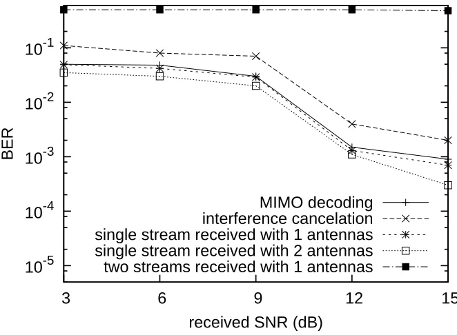
3.2.1 MIMO Decoding and Interference Cancelation . . . 26
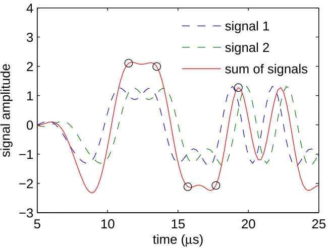
3.2.2 Timing Synchronization . . . 27
3.3 Simulation . . . 28
3.3.1 Simulation Setup . . . 28
3.3.2 Performance Evaluation . . . 31
3.4 Conclusion . . . 35
Chapter 4 QuickSense: Improving the Spectral Efficiency . . . 36
4.1 Analog-filter-based Spectrum Sensing . . . 37
4.1.1 Problem Statement . . . 37
4.1.3 Enhanced Algorithm using Fixed Bandwidth Analog Filters . . . 42
4.1.4 Energy Detection Threshold . . . 44
4.2 Discussions . . . 45
4.3 Evaluation . . . 46
4.3.1 Proof of Concept Experiment . . . 47
4.3.2 Trace-Driven Simulation . . . 53
4.4 Conclusion . . . 55
Chapter 5 ACMI: Improving the Efficiency of Indoor Localization . . . 56
5.1 Measurement and Observation . . . 57
5.1.1 Measurement Methodology . . . 58
5.1.2 Outside the Building . . . 59
5.1.3 Inside the Building . . . 60
5.2 Model and Verification . . . 64
5.2.1 Modeling Parameters . . . 66
5.2.2 Verification . . . 67
5.3 System Description . . . 68
5.3.1 Overview . . . 68
5.3.2 Offline Phase . . . 69
5.3.3 Online Phase . . . 71
5.4 Discussions . . . 75
5.5 Evaluation . . . 76
5.5.1 Experiment Setup . . . 76
5.5.2 Modeling Accuracy . . . 76
5.5.3 Localization Performance . . . 79
5.6 Conclusion . . . 83
Chapter 6 Conclusion and Future Work . . . 84
LIST OF TABLES
Table 3.1 Simulation parameters . . . 29
Table 4.1 List of 9 TV stations within the area and their distances to our building. . . 50 Table 4.2 Number of channel sensing per filter with QuickSense-B and QuickSense-E in
UHF TV band. . . 50
Table 5.1 Information of FM stations that we used for our measurements. . . 58 Table 5.2 Locations where RSS measurements were performed. . . 76 Table 5.3 The number of detected reference points and the trained parameters at each
LIST OF FIGURES
Figure 1.1 Wideband spectrum sensing problem: determine X = [x0,x1,···,xN−1]where
xi=1 if Channeliis occupied, and 0 otherwise. . . 2
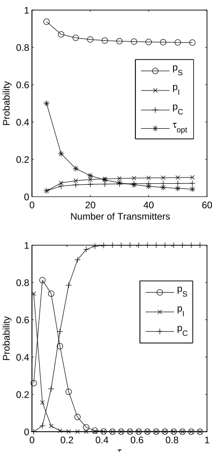
Figure 3.1 Examples of MIMO transmissions. Concurrent transmissions allow multiple transceivers from different nodes to transmit at the same time using the same frequency. . . 14 Figure 3.2 The basic media access mechanism of Contrabass MAC . . . 20 Figure 3.3 (a) Whenτoptis applied,pI,pSandpCis almost constant with different number
of transmitters. (b) pI and the pC are used for estimating the current level of
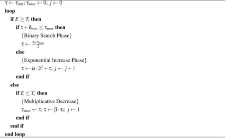
transmission attempt probability as they are monotonic functions, respectively. 22 Figure 3.4 Transmission probability control algorithm . . . 23 Figure 3.5 Contrabass GNURadio experiment setup. Two nodes are set up to be
transmit-ters and the other two nodes are receivers. Each node have two antennas and a transmitter uses one antenna for transmission and a receiver uses both antennas for receiving. A PC connected to radios via USB interfaces controls the experi-ment, and receives the dumped wave forms from the radio and performs offline signal processes. . . 26 Figure 3.6 BER performance of MIMO decoding and interference cancelation. . . 27 Figure 3.7 The receiver performs oversampling and perform the PHY takes the optimal
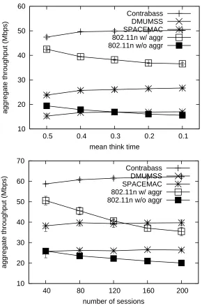
sampling index to resolve the timing error of multiple frames. . . 28 Figure 3.8 The aggregate network throughput when the traffic load is varied. (a) Web
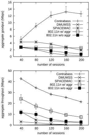
traf-fic. (b) FTP traffic . . . 31 Figure 3.9 Transmission success probability of Contrabass and 802.11n. . . 32 Figure 3.10 The result of the VoIP experiment. (a) VoIP goodput. (b) Aggregated throughput
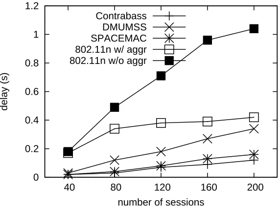
of the background FTP traffic . . . 33 Figure 3.11 Average packet delay of protocols. . . 35
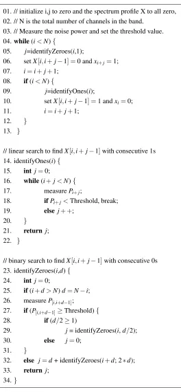
Figure 4.1 QuickSense doubles the filtering bandwidth until it detects an occupied channel. Then it shrinks its filtering bandwidth to find the occupied channel. Once it finds an empty channel, it increases the filtering bandwidth again. . . 38 Figure 4.2 QuickSense Basic Algorithm . . . 39 Figure 4.3 Basic QuickSense design using a single pair of a tunable lowpass filter and an
energy detector. . . 41 Figure 4.4 QuickSense Enhanced Algorithm . . . 42 Figure 4.5 Enhanced QuickSense design using log2(N)lowpass filters with different fixed
bandwidths and energy detectors. . . 43 Figure 4.6 Energy readings from empty channels. Filters with 2MHz, 5MHz, 15MHz and
32MHz bandwidths are used. . . 44 Figure 4.7 QuickSense benchmark device consists of analog hardware and a signal
Figure 4.9 As the number of energy readings is around 1,000, the noise estimation error becomes very low, around 0.5dB. . . 52 Figure 4.10 The ratio of false negative signal detection is shown with different number of
energy readings used for the channel sensing. Also the signal strength is differ-entiated. . . 52 Figure 4.11 Performance of sequential scan, QuickSense-B, QuickSense-E and compressed
sensing. Basic-8 and Enhanced-8 show the cases where every 8 channel is grouped together. . . 54
Figure 5.1 Example scenario of ACMI. . . 56 Figure 5.2 Locations of 8 available FM stations in the vicinity. . . 58 Figure 5.3 Floorplan of building. Red dots represent the spots where RSSs have been
sam-pled. . . 59 Figure 5.4 The measured and estimated RSSs outside the building. Average error is 3.8 dB. 59 Figure 5.5 Indoor propagation characteristics of FM broadcast signals. . . 61 Figure 5.6 The RSSs at outside the building, windows with LoS, without LoS and average
values are compared and averaged at 60 different spots. . . 62 Figure 5.7 Pass loss measurement at an indoor corridor shows the path loss exponent of 2.16. 63 Figure 5.8 BuildRSSDatabase(S, T, W) . . . 65 Figure 5.9 Comparison between model-generated RSS estimation with actual
measure-ments, for FM station 4 and 8, respectively. The cross-correlation is 0.54 and 0.70, and the median error is 4.5 dB and 3.3 dB, respectively. . . 67 Figure 5.10 Model-generated RSS distributions over the floor. Each column demonstrates
each algorithm step: (1) LoS signals only (2) NLoS signals added and (3) in-direct signals added, respectively. Each row is the distribution of signals from station 4 and 8. The FM stations are located south east and south west of the building, respectively. For the floorplan of the building, please see Figure 3. . . 68 Figure 5.11 Architecture of ACMI. . . 69 Figure 5.12 Required information for building the fingerprint DB. . . 70 Figure 5.13 Indoor positions along the walking path are recognized by walk detection. The
detected positions are used to (1) calibrate the model parameters and to (2) per-form the path matching. . . 72 Figure 5.14 Estimation error distribution in dB. . . 77 Figure 5.15 Euclidean distance representation of RSS vectors where X and Y axis represent
the indoor spot index. Left figures show the Euclidean distance between mea-surement vectors and right figures show measured and estimated vectors. The area in blue shows more similarity between two vectors than red. . . 78 Figure 5.16 Localization accuracy. . . 80 Figure 5.17 Distribution of localization errors of ACMI, after path matching. . . 82 Figure 5.18 Simulation results show that the performance of ACMI scales with number of
Chapter 1
Introduction
The exponential growth of mobile data has been a major challenge in wireless networks. It is expected
that the amount of mobile data will grow 18-fold between 2011 and 2016 [14]. But the network through-put has stagnated over the years. This is in stark contrast to the rapid increase in the link layer speed. The
main problem traces back to networking overheads, e.g., backoffs and packet collisions. Prior study [7]
confirms that any single-transmission based random access should have a clear limitation resolving such networking overheads.
Concurrent transmission can be an alternative to existing single-transmission based techniques. Here
the concurrent transmissions refer to simultaneous transmissions by multiple users over the same fre-quency, powered by multiple input multiple output (MIMO) technology. Concurrent transmissions have
a potential to amortize the networking overhead over multiple transmitters and thus largely mitigate the
networking overhead. The remaining challenges are twofold. First, the concurrent transmissions require the simultaneous acquisition of the channel state information (CSI) in between the multiple senders and
the receivers. Second, the distributed access does not guarantee the full utilization of the degree of freedom (DoF) of the MIMO channel. These difficulties have been giving births to a group of
proto-cols [13, 52, 54, 56, 72, 75] which try to perform complicated coordinations between the mobile nodes.
But they were hardly implemented in real systems due to the complexity and the poor performance. In the meanwhile, the increase in the mobile data has also led to a new dimension of problem: a
severe spectrum shortage, dubbed a spectrum crunch [15]. Recall that the ISM (industrial, scientific and
medical) band in 2.4 GHz, for example, allows only 100 MHz bandwidth for an unlicensed access. Con-sidering the explosive growth of the mobile data, this limited availability should be the major problem
in the near future.
Aware of and keen to resolve the problem, the US government has set the goal of freeing up to 500 MHz of spectrum [86]. In addition, recent measurements [65] reveal that, in the band between 30MHz
and 3GHz, there are at least several hundred spectrum holes, each of which more than 2MHz wide. In
So now the urgent task is to obtain the spectrum usage information, the occupancy of all channels
and their usage overtime, as shown in Figure 1.1. This spectrum map provides DSA devices a global
view on entire frequencies, thus contributing to the best selection of channels. If a mobile device has a complete spectrum map, it can make intelligent decisions on which channel to use at any particular time
and location. For example, a DSA device in need of a reliable connection can pick a channel that has
been the least interfered in the past. Another device, that prefers more link bandwidth, can try channel bonding [37] and choose a channel with more available neighboring frequencies.
x0
Channels
occupied available
xN-1
occupied available
Figure 1.1: Wideband spectrum sensing problem: determine X = [x0,x1,···,xN−1] where xi =1 if
Channeliis occupied, and 0 otherwise.
The goal of spectrum sensing is to figure out such spectrum usage information for DSA devices.
But the spectrum sensing is challenging because the entire search space is usually very large. While
sensing in narrow spectrum bands has been well studied, however, there does not yet exist any efficient broadband spectrum sensing technique. Using a wideband radio [67] might be one way but the required
hardware device is generally too expensive and power consuming. On the other hand, sequential scan
that linearly scans the entire spectrum can be very slow if the wide spectrum band contains many narrow channels.
Another important task remaining in mobile systems is indoor localization. The prevalence of smart devices has triggered the recent emergence of location-based services (LBS). Whileanywhereservices
is expected, however, satellite signals do not reach inside the buildings and therefore the GPS (global
positioning system) is not available indoors. To address this problem, there has been an urgent call for an accurate indoor localization technique.
Received signal strength (RSS) based techniques have been actively discussed among several branches
of studies. They are known to provide robust and accurate indoor localization [5, 97]. The RSSs from various signal sources form a position-specific signature. Thus given the signature DB, a mobile user
can query the current location based on the sampled RSSs. The merit is that this technique achieves good
in a building should be probed to store the corresponding RSS samples. This process is labor-intensive
and time-consuming, thus becoming the major bottleneck that hinders the technique from being widely
deployed in the real world.
Crowdsourcing might be an alternative way to the manual site profiling. Crowdsourcing distributes
the heavy load by asking each mobile user collaboratively contribute to build the fingerprint database.
But in this approach it is hard to expect that a mobile user can label the sampled RSSs with precise location, because the current location is not known to the user a priori at the moment. Therefore inputs
with at most room-level accuracy might be expected [24, 53]. Recent innovations [59, 83, 91] solve this problem with dead-reckoning powered by motion sensors (e.g., accelerometer, compass, etc.) and the
knowledge of floorplans or landmarks. Therefore the mobile users, unawarely, can report the current
location with measured RSS samples. Although this alleviates the issue, still, some non-negligible time duration might be required to stabilize the database and to start the localization service.
Another challenge with the current RSS fingerprint based localization is the vulnerability of the
sig-nal source itself. WiFi is being commonly used for the RSS-based techniques because of its abundance in the availability. It has been reported however that the WiFi signals, around 2.4 GHz or 5 GHz, are
very susceptible to human presence or orientation of mobile devices [9, 100]. Moreover the WiFi APs
are deployed without careful planning in many cases and therefore their configuration might be easily changed by individuals. This means that even with the extensive site profiling efforts, after some time,
it is highly probable that the RSSs sampled by mobile users do not match accurately with pre-surveyed
RSSs.
In this dissertation, we present Contrabass [95], QuickSense [94], and ACMI [93] in deliberate
efforts to address the aforementioned concerns in the mobile system. Contrabass is a practical
MIMO-based concurrent transmission protocol. The design choices of Contrabass are orchestrated towards the practical implementation. The MAC protocol is designed for each mobile user to transmit a packet with
optimal transmission probability, in a completely distributed manner. The PHY layer design enables
the simultaneous CSI acquisition between multiple users without any negotiation process. As a result, Contrabass builds as the first-to-date open-loop concurrent transmission protocol that operates without
any control message exchange. Contrabass maximizes the channel utilization, thus achieving very high
aggregate throughput, low delays and scalability even under dynamic environments. The performance is demonstrated through GNU radio implementation and experimentation.
QuickSense is an analog-filter based broadband spectrum sensing technique. QuickSense has the speed asymptotically as fast as compressed sensing that is theoretically proven to be the fastest
tech-nique. But unlike those techniques that are purely theoretical (e.g., compressed sensing) or too much
expensive (e.g., wideband radio), QuickSense has its own low-cost hardware implementation. The key insight of QuickSense is that, if the sum signal energy on a contiguous band is low, all the sub-channels
within this band are clear and therefore we do not have to investigate each of them. We achieve this
the hardware building block, we design an intelligent search algorithm that achieves channel sensing
with the minimum number of sensing operations. We mathematically prove that the algorithm has the
asymptotic complexity as low as that of the compressed sensing, while our design is much simpler and easily implementable in the real hardware. We show the availability of our technique using real
hardware devices. Extensive trace-driven simulation using real TV signals shows the effectiveness of
QuickSense.
Finally, ACMI is an FM-based indoor localization that does not require proactive site profiling.
ACMI constructs the RSS fingerprint database based on the pure estimation of indoor RSS distribution. Here the signals transmitted from commercial FM radio stations are used. For this, ACMI makes use
of our signal model harnessing public transmission information of FM stations, in a combination with a
floorplan of a building. Using the fingerprint database as the knowledge base, ACMI actively performs multi-level online signal matching to infer the current location of a mobile user. ACMI achieves good
indoor localization accuracy even without the site profiling efforts. We evaluate ACMI with extensive
indoor experiments in 7 different locations with over 1,100 indoor spots. The results show that ACMI achieves up to 89% room identification and accuracy of 6m localization error on average using 8 FM
broadcast signals.
1.1
Outline of the Dissertation
In this dissertation, we propose three separate solutions for mobile systems. Contrabass improves the
network throughput by innovating the MAC and PHY of the wireless communication stack. QuickSense implements the fast and energy-efficient channel sensing by adding analog hardware to the mobile radio
front-end. ACMI finds the indoor location of mobile users using FM RSS samples and readily
avail-able transmission information. These solutions deal with different aspects of mobile systems and can contribute to enhance the system capability. In Chapter 2, we provide the background information and
relevant studies. We aligned each topic under the separate sub-sections to help easier reading. In Chapter
3, we describe the details of Contrabass. We illustrate the MAC and PHY layer protocol of Contrabass, and then explain the GNU radio experiments and simulation results. Chapter 4 presents QuickSense. We
elaborate the basic and upgraded version of QuickSense designs and mathematically show its asymptotic
complexity. Then we prove the effectiveness of QuickSense via the proof-of-concept experiment and trace-driven simulations. In Chapter 5, we present ACMI. We first outline our findings from the field
ex-periments. Based on the findings, we model the indoor RSS distribution of FM signals. Further online
Chapter 2
Background and Related Work
This chapter presents background and relevant studies in three different aspects of mobile systems.
Section 2.1 surveys multiple user communication protocols that enables the concurrent transmission. Section 2.2 presents existing spectrum sensing techniques that surveys the channel usage in a broadband
spectrum. In Section 2.3, we describe the proposals which performs the indoor positioning for mobile
systems.
2.1
Concurrent Transmission Protocols
2.1.1 Concurrent Transmission in Theory
There have been great advances in theoretical multi-user MIMO [23,77,81], especially in the area of the
optimal research design. These studies are theoretical because they typically do not consider practical issues such as estimation of channel coefficients, and frequency and timing synchronization. Since we
focus on MUC for CSMA networks, we limit our discussion on recent advances in practical MUC for
CSMA networks.
Commercial CDMA receivers at a base station (BS) has decoded a user by treating all other users
as noise [8]. However, CDMA is highly suboptimal in high SNR environment like WLANs. Recently
successive interference cancelation (SIC) has been used to decode interfering users in CDMA cellular networks. But SIC requires the interfering senders to have significantly different levels of power or
coding [30]. In the literature, the user of multiple receive antennas in the uplink is often called
space-division multiple access (SDMA): we can discriminate among users by exploiting that different users have different spatial signatures on the receive antenna array. In this SDMA network, MMSE with SIC
2.1.2 Concurrent Transmission Systems
SIC [30] exploits the capture effect arising in wireless networks to decode collided packets. When two
or more packets collide, a receiver first decodes a packet with the strongest signals, subtracts them from the received signals. Then it decodes the weaker ones from the residue. The biggest limiting factor of
SIC is its requirement of significant signal strength differences among overlapped signals. Senet al.
argue that from the perspective of MAC design, the gain achievable by SIC is marginal because of the requirement [71].
ZigZag [27] was designed to solve the hidden-terminal problem. ZigZag exploits a repeated
inci-dence of collisions by the same set of packets which can happen through retransmissions by hidden terminals. While ZigZag significantly reduces MAC overhead, it requiresnretransmissions to decoden
packets.
IAC [28] enables MUC in a network of multiple APs even when the number of senders is larger
than the number of receiving antennas at an AP. For this, multiple clients cooperate to align their signals
using transmit beamforming so that their transmitted packets are detected as if coming from a single source. IAC can operate even when the number of antennas in each AP can differ from each other. This
allows the total number of transmitted packets to appear not exceeding the degree of freedom (i.e., the
number of antennas) at the AP. The AP decodes the other non-aligned packets using MIMO and then transmits the decoded packets to a second AP through a wired connection that would have received
the same signals from the clients. The second AP then applies interference cancelation on the received
signals since the interference from the decoded packets (sent by the first AP) is now known. Since IAC utilizes beamforming which incorporates channel feedback from the AP and also requires changes in
the media coordination of CSMA clients, it should modify the existing standard CSMA clients (e.g.,
IEEE 802.11). N+ [46] can serve as a general framework for networks where devices with different number of antennas interoperate.N+helps to fully utilize the channel by increasing the number of data
streams when additional degrees of freedom are available.
For interference alignment at an AP, a mobile node should receive the channel side information (CSI) and the spatial direction of interference from the AP even though the mobile node’s corresponding AP
is not the AP. The CSI can be easily obtained by the channel reciprocity but the mobile node should
track the CSIs from the multiple APs. Furthermore, the wanted interference direction at an AP varies according to its scheduled mobile node at each time-slot and this information should be shared with
other APs. However, this AP coordination may not be feasible in commercial networks including WiFi
and Zigbee because most commercial unmanaged wireless network operates with CSMA protocol in which AP cannot know the scheduled users in each time-slot. Furthermore, coordination between APs
results in additional delay for successful decoding of collided packets.
transmissions of the collided packets are serialized so that any two or more preambles are not
over-lapped. Suppose that there is annpacket collision. The first preamble is always transmitted in a clean
channel. This enables the receiver to recover the physical layer parameters such as CFO, TPO and CFI) of the first packet which are used by the receiver to nullify the signals of the first packet from the received
signals. This exposes the preamble of the second packet in a clean channel. This nullification is repeated
to nullify the firstn−1 packets. Now then-th packet can then be decoded without interference, after which that packet is subtracted from the received signals. The interference cancelation are repeatedly
applied to recover all the remaining packets in the reverse order of the preamble transmissions.
Aryafar et al. implement a downlink MUC scheme using MIMO APs, which enables the AP to
send multiple packets concurrently, each destined to a different receiver [4]. It provides a practical
implementation and an experimentation of zero forcing beamforming.
Techniques have been suggested [49, 58] that synchronize transmitters such that received signals at
a receiver have similar physical layer characteristics (e.g., arrival time, carrier frequency offset or CSI).
SourceSync [58] implements such an idea with FPGA hardware programming. This type of sender cooperation can significantly improve the quality of signals received at the receiver.
The aforementioned techniques occupy the interference cancelation (IC) technique in common;
when a receiver successfully decodes one packet, it subtracts the signals of decoded packet from mixed signals. While this technique is intuitive and might work well when the number of colliding packets
is small, it has following shortcomings. First, IC introduces complicated operations. When a receiver
tries to subtract a decoded packet from mixed signals, it has to re-apply measured channel coefficients and CFO to the decoded signals in order to completely restore the clean copy of the packet. Received
signals are usually distorted and are different from the final version of decoded signals. Second, as SIC
is an iterative algorithm, an error in the first packet propagates through rest of the operations. For exam-ple, assume that the first decoded packet had a symbol error in it. Then the remaining signals after the
subtraction will be affected by the symbol error. Also, as it is almost impossible to completely restore
the original signal, SNR degradation occurs when subtraction is performed. So there is a limit in the number of decodable packets using SIC. Finally, IC is not scalable because of its processing delays.
The processing time of IC linearly increases with the number of colliding packets. Also, a receiver can
start IC operation only after full packets are received and stored in the local buffer. Hence IC is not appropriate for the real time processing of signals.
2.1.3 Expenses for the Concurrency
In order to implement the concurrent transmission in a mobile ad hoc networks, [13,72] perform
simulta-neous transmission of RTS and CTS, while [52,54,56,75] use separate staggered RTS and CTS message
signals. While the assumption on the perfect knowledge of CSI is unrealistic, use of spreading coding
incurs significant overhead because RTS and CTS are transmitted at a low data rate and spreading each
symbol consumes too much channel resource. Although Contrabass also uses PN-sequence for channel training, its use is limited to training sequences (about 31 symbols). On the other hand, encoding the
entire frames (typically 14 bytes) of RTS and CTS incurs too high overhead (assuming 8 symbols/bit spreading factor, 1792 symbols (14×2×8×8)).
2.1.4 Scheduling Algorithms
The existing protocols also differ in the scheduling algorithms that select concurrently activated links in the second phase. This is based on various factors such as traffic demands and diversity gains which
are gathered using the control messages. While some protocols [52, 54, 56, 75] limit the degree of concurrency, [13] [72] propose optimal scheduling algorithms that fully exploit both spatial gains, array
and diversity gains. However, most of these scheduling algorithms require complicated computations at
the time scale of per-packet transmissions.
2.2
Spectrum Sensing Techniques
2.2.1 High Performance ADC
A possible approach to perform the broadband spectrum sensing is to perform wideband scan using
an advanced device, such as high performance analog-to-digital converters (ADCs). However the high
speed ADC is very expensive, power consuming and requires extensive computation for the signal processing [44]. For example, in order to detect 500MHz bandwidth 1 Giga samples per second ADC
is required. But consumes 2,200mW and costs $775 [67] as of 2013. Thus this wideband scan is not suitable for mobile devices that have limited energy.
2.2.2 Narrow Band Sensing
There has been a large body of work on narrow band sensing [98]. The techniques are either based on
detecting the signal energy or the signal signature. The signatures include waveform or cyclo-stationality
of the signals. When known, the signature-based techniques can detect signals with extremely low SNR. However, these techniques are complicated and prior knowledge of received signals is required.
Such narrow band sensing techniques do not scale with the bandwidth of the spectrum. It is required
to investigate each narrow band channel one by one within the broadband spectrum. So this approach always performsN searches, whereN is the number of channels. Now imagine there are hundreds or
thousands of available channels. Since each scan on a narrow band channel may take severalms to
2.2.3 Compressed Sensing
There have been much advances in the theoretical study of compressed-sensing-based techniques [6, 43,
60,76]. These proposals perform sub-Nyquist sampling using low rate ADC and can achieveO(k·logN) searches wherek is the sparsity of the spectrum. However, prior knowledge of k is usually required,
which is not feasible in DSA networks where mobile devices frequently join and leave.
These techniques in common propose to perform random sampling in the analog domain. Those analog samples are combined with a combination matrix to infer the spectrum usage information. The
matrix is obtained via the training process. Since the process has to be performed in the analog domain,
dedicated hardware architectures are needed [6, 76]. To the best of our knowledge, there is no low-cost implementation of the compressed wideband sensing. For instance, analog buffers are used to store the
signal input before the quantization stage. The special hardware, that is capable of doing matrix multipli-cation in the analog domain, is also required. Real-world implementation of compressed-sensing-based
spectrum sensing is therefore very challenging, and there has not yet been any real implementation of
such techniques. The accuracy of the spectrum sensing depends on the compression ratio (higher means retaining more samples). Prior works [43, 60] usually assume that the sparsity of the signal is known.
Recently Meng et al. [48] proposed a collaborative compressed spectrum sensing approach. Each
node is equipped with a frequency selective filter, which linearly combines multiple channel informa-tion. The linear combinations are sent as reports to the fusion center, where the occupied channels are
decoded from the reports by compressed sensing algorithms. By exploiting the sparsity of occupied
channels, the number of reports needed by the fusion center is reduced. However gathering reports introduces significant delay.
2.2.4 Geo-location Database
FCC has mandated the secondary users to query a geo-location database on occupied channels in a
particular location [21] to check the availability of TV “white space” channels. Still, spectrum sensing
helps in the following settings. First, the current geo-location database does not provide any information about other secondary users within the area. Thus, there are no means to arbitrate among multiple DSA
devices in the same location.
Second, the geo-location database can only approximately predict the signal reception quality at a location and could be inaccurate. While the geo-location database approach relies on certain propagation
models for the prediction, e.g., [66], due to the complexity of radio propagation and the changing
envi-ronment, the prediction model might not provide fine information. Finally, accurate and fast spectrum sensing technologies can help increase the spectrum efficiency. For example, a secondary user can
op-portunistically use a channel during the time interval between primary users’ transmissions when a short
802.22 [2], IEEE SCC41, and companies [64] have already started working on such spectrum sensing
technologies.
2.3
Indoor Positioning Techniques
2.3.1 Fingerprint-based Techniques
RADAR [5] has pioneered the RSS fingerprint-based indoor localization. At each indoor location,
broadcast packets from WiFi APs are overheard. The RSSs from multiple APs form a single vector
representing the specific location and by performing look-ups within the pre-built database the current location can be found. Horus [97] advances the technique by introducing a probability based inference
model, where the RSS from an AP is modeled into a random variable that varies according to time and
location. Apart from the RSS, a recent technique [70] utilizes the channel impulse response of WiFi as the location-specific signature and achieves highly accurate indoor localization. While these techniques
are very accurate, they require the labor and time intensive site profiling where every indoor spot should
be manually matched with corresponding fingerprints. In case WiFi is used as the signal source, this site profiling should be performed repetitively due to the significant temporal variances of WiFi signals.
Crowdsourcing is an alternative way for sharing the load among multiple users. The problem is
that it is difficult for such mobile users to label the collected RSS samples with accurate location in-formation [24, 53]. Recent innovations [59, 91] solve this problem by the use of the floorplan and the
movement detector. Still, it takes time for convergence of the fingerprint DB.
2.3.2 Model-based Techniques
To avoid the manual profiling processes researchers suggested to automatically generate the look-up DB, based on known radio wave propagation characteristics [12, 35, 45]. Lim et al. proposed a
tech-nique [45] that, by observing WiFi RSSs and finding the linear relationship with geographic distances,
builds the signal-distance map. This signal-distance map can be used to locate a mobile user’s location. Ez [12] also builds RSS-distance equations, but exploits genetic algorithm to solve the equations. These
two techniques basically base upon log-distance propagation model but do not explicitly assume any
prior knowledge about infrastructures or deployments. They automatically obtain essential information from a few initial measurements. ARIADNE [35] uses floorplan together with sophisticated ray tracing
method. By using known locations of WiFi APs and transmission powers, it can automatically generate
the look-up DB.
Modeling approaches other than RSS also exist such as Time of arrival [85], time difference of
arrival [10] and angle of arrival [88]. They achieve highly accurate localization. However, these
2.3.3 FM-based Localization
There have been growing research interests regarding FM-basedoutdoorlocalization. The advantage is
that FM signals cover very wide area (up to 300 km), they have good availability of signal sources and FM radios consume less power compared to GPS or WiFi. FM signal can be used to detect a mobile
user [42] or a passing object [34] outdoors. Youssef et al. showed the feasibility of the
FM-modeling-based technique in an outdoor setup [96]. Based on the signal strength model and the calibration, 8 km accuracy has been achieved. But the main difficulty with the RSS-based approach is that the
RSSs of FM signals do not significantly vary within nearby outdoor locations because of the strong
transmission power. Therefore, close-by areas within small distances are often indifferentiable with FM RSSs. The linear relationship between the displacement and the signal phase of FM pilot signal can be
considered [40] but it has not been verified experimentally.
Recently, Chen et al. inspired the research community by experimentally showing the feasibility of
FM RSS-based indoor localization [9]. Unlike the outdoor environment, indoor structures create various
shadow-like attenuation patterns that can be preferably used as signatures for the positioning. With FM RSS alone, they achieved up to 92% room level identification. In the meanwhile, they showed that the
FM signals are robust to fading, human presences and changes in mobile devices’ orientations unlike
WiFi. It has been also shown that FM signals do not experience much temporal variations as WiFi signals.
2.3.4 Indoor Propagation Models
The well-known log-distance propagation model estimates the signal strengths of radio signals as
P(d) =P(d0)−10·n·log10(
d d0
) [dBm],
whereP(d), the received power at distancedis given by subtracting the attenuation factor fromP(d0),
the signal strength at reference distanced0, usually set to 1m. Herenis the path loss exponent that is
obtained experimentally. This simple log-distance model is not accurate indoors for following reasons. First, there could be obstacles between the transmitter and the receiver that further attenuate the signals.
Second, this model assumes that the transmission power is equal (isotropic) in all directions, while
nowadays many WiFi APs occupy antenna arrays or directional antennas and therefore they are non-isotropic. Finally, this model does not take into consideration the non-line-of-sight indirect signals that
traverse longer paths than the direct signals.
to FM signals at very high frequency (VHF) that range from 30 MHz to 300 MHz; the propagation
of higher frequency signals is very rectilinear, while VHF signals around 100 MHz experience severe
diffraction. Also, those studies only consider the case where a transmitter is inside the building. In our model, we consider the indoor propagation of FM broadcast signal where the transmitters are usually
tens of miles away.
Another line of study [36, 80, 90] is to build a mathematical model. The ray tracing technique was originally used in 3D graphics analysis. It tracks virtually infinite number of very smallray tubes
that stem out from the transmitter. Direct propagation, reflection and diffusion of a radio wave can be accurately modeled by the ray tube. Accumulating the ray tubes at each spot on the floor, the ray tracing
can accurately predict the indoor RSS distribution. But the ray tracing cannot be used in our system for
the following two reasons. First, the transmitter is too far away, which makes it impossible to model the traversal path of ray tubes. It is not known which obstacles are in between the building and FM
transmitters. Second, the ray tracing technique is computationally complex. Computation of a scenario
where the transmitter is just tens of meters away takes several hours [90]. Therefore, in our case the heavy computation may kill the practicality of our system. But we can consider this as one of future
Chapter 3
Contrabass: Improving the Mobile
Throughput
An important attribute of multi-antenna processing is the ability to null out co-channel interference for
improved signal quality. Interference can be canceled at the transmitters by using pre-coding techniques,
at the receivers by adjusting antenna weights, or both. This ability enablesconcurrent transmissions, de-fined to be simultaneous transmissions over the same carrier frequency by multiple transceivers residing
in the interference ranges of each other.
Consider a network where each node hasmantennas. In theory, up tomconcurrent transmissions can be successfully decoded at receivers using the multiple input multiple output (MIMO) detection
techniques such as zero forcing (ZF), minimum mean squared error (MMSE) and maximum likelihood
(ML). Any concurrent transmissions by more thanmtransceivers are considered ascollision. The recent standard for MIMO communication, namely IEEE 802.11n [1], adopts only a special case of concurrent
transmissions in which only one node is involved in the transmission at a time, using all or part of
its antennas and transceivers. The CSMA/CA is used as an MAC protocol to ensure only one node within an interference range to transmit at a time. We refer to this type of concurrent transmissions as
exclusive transmissions, which is also called single-user MIMO in the literatures. Figure 3.1 illustrates
Figure 3.1: Examples of MIMO transmissions. Concurrent transmissions allow multiple transceivers
from different nodes to transmit at the same time using the same frequency.
The exclusive transmissions miss out many opportunities of concurrent transmissions. With
ex-clusive transmissions, a packet can be transmitted at a rate proportional to the number of transceivers (i.e., theoretically mtimes a link rate), so the transmission time of data is much shorter than using a
single transceiver. However, control overhead such as time duration due to collisions, channel training,
SIFS and DIFS, and ACK transmissions must still be incurred per packet. To mitigate the effect of this overhead, IEEE 802.11n aggregates multiple packets and transmits them as a single large frame.
Although the aggregation amortizes the overheads over multiple sub-packets, there are situations where
aggregation may not be possible due to the delay constraint of the packet. Concurrent transmissions, on the other hand, can naturally implement this amortizement without incurring delays because they
permit multiple nodes to transmit at the same time. Furthermore, the transmission policy of FCC for
un-licensed spectrum bands limits the per-node transmission power and in the exclusive transmissions, all antennas are co-located in the same node and the transmission power per antenna should be decreased
as the number of transmit antennas increases [20]. However, in concurrent transmissions the transmis-sion power per node remains constant independently of the number of concurrently transmitting links as
long as the transmitters are in different nodes. The total power used for data transmission is increased
as the number of concurrently transmitting nodes and the total data rate also increases compared to that of the exclusive transmissions with the same number of transmit antennas. See Sundaresan et al. [72]
for initial performance comparison between concurrent transmissions and exclusive transmissions.
Realizing the full potential of concurrent transmissions requires an effective co-design of PHY and MAC protocol where interference cancelation and collision avoidance should work toward the same
goal. The biggest challenge is to minimize the control overhead of the protocol. There have been a
number of proposals for concurrent transmission protocols including [13, 50, 52, 56, 72]. Unfortunately, none of them is used in real systems because of high control overhead for supporting concurrent
trans-missions which diminishes the performance gain of concurrent transmission. Most overhead is incurred
training.
Most of the earlier concurrent transmission protocols for ad hoc networks run in two phases. In
the first phase, they perform RTS and CTS handshaking during which they perform exclusive channel training. During the transmission of RTS and CTS, no other transmitters can transmit so that each
transmitter and receiver pair can learn the channel state information (CSI) without any interference
from other transmitters. Typically, RTS and CTS embed training sequences needed for channel training. Another important task that RTS-CTS coordination performs is to determine the set of transmitters that
can transmit during the second phase. The total number of concurrent transmissions in the second phase should not exceed the number of antennas at the receivers. In the second phase, concurrent transmissions
by the chosen set of transmitters take place to transmit data packets. Since RTS and CTS must be sent
at a low rate, this handshaking incurs very high overhead.
In this chapter, we provide a joint PHY/MAC protocol for MIMO based concurrent transmissions
in ad hoc networks which does not involve infrastructures and operates without any coordination. By
no coordination, we mean that the protocol must not introduce control frames other than ACK. The protocol is calledContrabasswhich is named after CONcurrent TRAnsmission.
There are a number of challenges for coordination-free concurrent transmissions. First, a receiver
needs to estimate the channel state from a transmitter without any explicit coordination. The difficulty lies in that a receiver does not know in advance who will send without prior coordination. Second, the
number of concurrently transmitting transceivers must be kept to less than or equal tomto avoid
colli-sion. To solve these problems, Contrabass implements simultaneous channel training by developing a set of innovative PHY-level techniques. Simultaneous channel training ensures channel training of
con-currently transmitting channels without explicit and separate coordination. The accompanying MAC
protocol of Contrabass achieves near optimal channel utilization by ensuring, again with no coordina-tion, the number of concurrent transceivers as close asmfor high channel utilization. Such a control
is non-trivial because no prior information is given about the time-varying number of contemporarily
competing transceivers, potentially located at different nodes.
We have implemented the PHY portion of Contrabass in the GNURadio platform [25] and conducted
a proof of concept experiment (Section 3.2). Our experiment indicates that Contrabass successfully
de-codes signals from concurrent transmissions using its PHY protocols. Since GNURadio do not permit an effective implementation of real-time carrier sensing (see [51]), we implemented MAC of Contrabass
and other MIMO protocols using NS-2. Here, Contrabass and two of existing concurrent transmission protocols, and IEEE 802.11n are tested under diverse network and traffic conditions. We verify through
simulation that Contrabass yields high scalability under various traffic loads and outperforms the
exist-ing concurrent transmission protocols. Compared to IEEE 802.11 with frame aggregation, it achieves about 60 to 70% performance improvement with aggregated throughput under high load and about 4x
3.1
Simultaneous Multiple Access based on Smart Antenna Array
In this section, we present our protocol, calledContrabassthat implements coordination-free concurrent
transmissions. Contrabass consists of PHY and MAC components.
3.1.1 Assumptions and Definitions
Each node is assumed to havemantennas. We refer to an antenna and its corresponding transceiver as atransmitter. Themdifferent transmitters in concurrent transmissions may or may not belong to the
same node. A transmitter isactiveif it has a packet to transmit. We define achannelto be the wireless link between a transmitting antenna and a receiving antenna. There arenactive transmitters in the same
interference range and a subset of transmitters transmit simultaneously. We assume that the number of
concurrently transmitting nodes is equal tontx. A node cannot receive and transmit at the same time
(i.e., half-duplex node).
Consider from a perspective of a receiver receiving signals throughmantennas. Let us denote the
channel coefficient from transmitterito the jth antenna of the receiver ashi,j. Then the MIMO channel
is described asy=Hx+wwhereyis anmdimensional receive vector,xis anntxdimensional transmit
vector,wis anmdimensional additive white Gaussian noise vector and H is them×ntxchannel response
matrix.
Given a rich scattered environment such as Rayleigh fading channel, wireless signals experience
diverse paths to the destination and the channel coefficients become linearly independent from each
other. With ntx ≤m, it is possible for a receiver to recover the original input vector x. Normally a
channel filter is built for the process. The linear channel filterW is anntx×mmatrix such that ˆx=Wy
where ˆxis the estimation of the original input vectorxby the receiver. The receiver must estimate all
channels ofntxtransmitters through channel training in order to obtainW.
3.1.2 Physical Layer Protocol
Contrabass implements simultaneous channel training by embedding a unique training sequence in the preamble of each data packet. We perform a set of PHY-level signal processing techniques to implement
simultaneous training using the training sequences. A receiver performs RLS (recursive least squares)
filtering on the received signal (containing the training sequences super-imposed together through simul-taneous transmission) to create a channel filter for a receiver without explicitly and separately estimating
all the contributing interfering channels. Since in concurrent transmission, it is possible that multiple
data packets are transmitted to the same receiver, a receiver needs to build multiple channel filters, each tuned to the channel state from each contributing transmitter. To enable this, we use two additional
their training sequences. Since multiple transmitters might be located at different distances from the
re-ceiver, received signals may have different powers. This is commonly called the near-far problem. SIC
is applied to to enhance the performance of training sequence extraction even under differing received powers of multiple signals. With exception of RIC, RLS and SIC are previously developed [30, 32, 55].
Our key contribution in the PHY layer is the innovative combination of these techniques to enable
si-multaneous channel training without coordination.
Training Sequence
In wireless communication, training sequences (TS) are commonly used for time and frequency syn-chronization and channel estimation. Typically TS is embedded in the preamble of each data packet. In
Contrabass, to enable simultaneous channel training, we use training sequences with low cross
correla-tion. For channel training, a receiver needs to know in advance the TS embedded in received frames. There are two choices of training sequences that a transmitter embeds in its transmitted frame to a
re-ceiver. The first choice is for a transmitter to compose a unique TS and embeds it into the frame. This
requires its receiver to know in advance which transmitter is transmitting to it. The second choice, adopted by Contrabass, is that each receiver generates its unique TS from a well-known unique ID such
as its MAC address. Since a transmitter knows the MAC address of its receiver, it can also generate and embed the TS of the receiver in the preamble of its frame. The receiver simply needs to match the
received training sequences with its own. One issue with this approach is that concurrent transmitters
sending to the same receiver will use the same TS. In order to distinguish these overlapped TS’ without coordination, we devise a novel technique called RIC (described further next section) where each
Con-trabass transmitter varies its starting index of TS randomly. A ConCon-trabass receiver correlates its TS with
received signals by rotating the starting index of its TS. To maximize the chance of identifying the TS’ of those concurrent transmitters, we use training sequences with very low auto-correlation. As a result,
we adopt gold sequences which have very low cross/auto-correlation [26].
Random Index Correlation
Contrabass uses 31 symbol gold sequences for channel training. Denote by f(i)the symbol at theith
position of a TS. Each transmitter picks a random index jfrom 0 to 30 and use the index as a starting position to transmit to its receiver in the following way. The symbols are rotated by j so that f(i) is
placed at(i+j)mod 31. This rotated TS is embedded in the preamble.
Suppose that ntx transmitters simultaneously send their frames. By the MAC protocols, all these
frames are synchronized and exactly overlapped. The receiver performs a cross-correlation function
C(t)by performing a convolution starting from index 0 to index 30.
C(t) =
30
∑
k=0where f∗is the complex conjugate of the training symbol andgis the received symbol such thatg(k) =
h1x1,k+···+hntxxntx,k, wherehiis the channel coefficient between transmitteriand the receiver, andxi,k is thekth symbol of the training sequence received from transmitteri.
RIC finds indexssuch thatC(s) =|max0,30C(t)|. When a numberscoincides the starting index of
a training sequence from a certain transmitter, say 1, the correlation value will be
C(s) = h1 30
∑
k|x1,k|2+···+hntx
30
∑
kx1,k·xntx,k ,
where ¯xis the complex conjugate of the symbolx. With the TS having a pseudo orthogonality, it will have∑i6=1,kx1,k·xi,k'0. Hence, we will have the correlation peak of
C(s)' |h1| 30
∑
k|x1,k|2. (3.2)
Recursive Least Squares Filtering
RLS filtering [32] trains a channel filterW directly from the input signal without explicitly estimating CSI and CVM (covariance matrix) using the following iterative algorithm.
Wi=Wi−1+ (xi−Wi−1yi)y∗iPi,
Pi=λ−1[Pi−1−λ
−1P
i−1yiy∗iPi−1
1+λ−1y∗
iPi−1yi ].
xi indicates anm-dimensional vector defined as[s1s2. . .sntx0. . .0]
T where s
j represent theith symbol
of the TS from the jth concurrent transmitter andntxis the number of the received frames to the same
receiver. Therefore, by using RLS filter, up tomframes can be decoded and unknown interferences from
other concurrently transmitting nodes to other receivers can also be effectively suppressed at the same time. The initial value ofPi is given asP−1=ε−1I whereεis a very small constant. λis a forgetting
factor, 0λ<1.Wiconverges iteratively toWwith an error feedbackxi−Wi−1yiwithout the need for
estimatingHand its covariance. RLS is known to have a SNR performance same with MMSE [84].
Successive Interference Cancelation
After a training sequence of a frame is correctly identified and used for channel training via RIC and RLS filtering, a Contrabass receiver cancels out the contribution of that training sequence from the
received signals in the following way. First, the average channel coefficient of the decoded symbols, ¯
h, is obtained (e.g. h1 in Eq. (3.2)). Then, the recovered symbols in the TS and the data frame are
RIC and RLS to extract the second packet. This process is repeated until the extracted payload does not
pass the integrity test or the receiver could not find a correlation peak.
In general, SIC is effective only when the signal strength ratio among interfering frames is large enough for the demodulator to decode symbols. This requirement interferes with rate adaptation [27].
In our protocol, this problem does not occur since SIC is applied only for training sequences and training
sequences are always transmitted at a fixed rate. In addition, a receiver already knows its own training sequence which will be subtracted from the original signals. After finding the starting index using
RIC, indicated by the correlation peak with the known TS, the known TS can be subtracted from the received signals. Since no decoding is involved in this stage, the signal strength ratio among interfering
frames does not need to be large. Furthermore, since SIC is applied only to TS, it consumes very
little computational resource. Note that the data portion of a frame is decoded using the channel filter obtained from RLS filtering without using SIC.
3.1.3 MAC Layer Protocol
The MAC protocol of Contrabass needs to achieve the following goals. (1) Contrabass requires every
concurrent transmitter within an interference range to transmit at the same time and (2) the total number
of concurrent transmitters must be less than or equal tomfor collision avoidance, but as close tomas possible for high channel utilization.
To achieve the first goal, Contrabass adopts CSMA where each active transmitter performs
carrier-sensing before transmission. After the medium becomes idle, each node waits for a fixed time interval (typically called DIFS in IEEE 802.11 standard). This ensures that all the concurrent transmitters start
their transmission right after the DIFS and no new transmission can start in the middle of the other
concurrent transmissions in the same range. As interference ranges are different from sensing ranges, this does not necessarily guarantee simultaneous transmission within an interference range. However,
this can be considered as a good approximation. Note, if there is a hidden terminal outside the sensing
range, it is possible that a new transmission may start in the middle of the other concurrent transmissions. Note that the same problem may also occur with IEEE 802.11n. A conventional technique to handle
hidden terminal is to use RTS and CTS. But in practice, RTS and CTS are not commonly used because
of their overhead. Furthermore, there are studies indicating that hidden terminals do not frequently occur [39]. If hidden terminals happen, their impact is no worse in Contrabass than in IEEE 802.11n
without RTS and CTS.
At each time of transmission, an active transmitter transmits a new frame with a probability τ. Fig. 3.2 illustrates the basic structure of Contrabass MAC. To achieve the second goal, Contrabass
adjustsτin a way that the probability of successful transmissions is maximized. In this section, we first mathematically derive the optimal transmission probability,τopt, that maximizes the success probability
transmission successes and idle slots so that it quickly converges toτoptwithout the knowledge ofn.
Figure 3.2: The basic media access mechanism of Contrabass MAC
After the successful receptions, ACK frames are sent back to their transmitters. As the duration
of packet transmissions could vary due to different payload sizes and data rates, all the receivers wait
until the last data transmission finishes. If the channel becomes idle again, within a pre-defined time interval calledshort inter-frame space(SIFS), all the successful receivers send ACK frames back to their
original transmitters. Those receivers that receive multiple frames send ACK frames using their multiple
transceivers. To ensure that the transmitters decode the ACK frames correctly, the receivers attach the unique training sequence that is generated from the MAC addresses of the transmitters. A receiver sends
the training sequence again starting from a random index so that the transmitter can decode concurrently
received ACK frames.
Optimal Transmission Probability
Suppose that the number of active transmitters nis known. Recall that the transmission is successful
only when the number of simultaneous transmissions within the interference range is less than or equal tom. Given that the transmitters transmit their frames with probabilityτ, we can express the probability of successful transmission,pSby adding the probabilities of all the events that the number of concurrent
transmissions is less than or equal tom:
pS= m
∑
i=1n
i
τi(1−τ)n−i, (3.3)
pI= (1−τ)n, (3.4)
As in Fig. 3.3(b), the transmission success probability is a concave function ofτ. We can find theτopt
by findingτthat makes the first derivation of Eq. (3.5) 0. The first derivation of Eq. (3.5) with respect toτgives
p0S = m
∑
i=1n
i
(iτi−1(1−τ)n−i−
(n−i)τi(1−τ)n−i−1). (3.6)
We can observe that the second term iteratively cancels out the first term in Eq. (3.6). Now, Eq. (3.6) can be simplified into
p0S = n(1−τ)n−1−n
n−1 m
τm(1−τ)n−m−1.
Finally, by findingτthat renders p0Sto 0, we easily obtain the optimal transmission probabilityτopt
that maximizes Eq. (3.5):
τopt=
1
m q
n−1
m
+1
. (3.7)
Binary Search Algorithm
In this section, we present a binary search technique that dynamically adjustsτto converge toτopt for
an unknownn.
The intuitions of the algorithm start from two observations. First, Fig. 3.3 (a) shows the values of
τopt as nchanges. It also plots the corresponding success, slot idle and collision probabilities under
a given τopt value which are denoted by poptS , p opt
I and p
opt
C , respectively. These probabilities remain
almost constant for large n. This property allows each transmitter to adjust itsτ so that its observed numbers of idle slots, transmission success and collision approximates those observed whenτis equal toτopt. Second, in Fig. 3.3, we observe thatpIdecreases andpCincreases monotonically asτincreases.
By observing pI and pC, we can tell whetherτis larger or smaller thanτopt. τis increased when pI is
larger than poptI and decreased when pC becomes larger than poptC . Note that poptI and p opt
C are known
0 20 40 60 0
0.2 0.4 0.6 0.8 1
Number of Transmitters
Probability
p
S
p
I
p
C τopt
0 0.2 0.4 0.6 0.8 1
0 0.2 0.4 0.6 0.8 1
τ
Probability
p
S
p
I
p
C
Figure 3.3: (a) Whenτopt is applied, pI, pSand pC is almost constant with different number of
trans-mitters. (b) pI and the pC are used for estimating the current level of transmission attempt probability
as they are monotonic functions, respectively.
In Contrabass, a node observes the results of any transmissions occurring within its carrier sensing