Core Size Optimisation of Variable Power
Inductor in DC-DC Converter
Sherina Harilal 1, Ratheesh.M.A 2
P.G. Student, Department of Electrical and Electronics Engineering, Vidya Academy of Science and Technology,
Thalakkottukara, Kerala, India1
Associate Professor, Department of Electrical and Electronics Engineering, Vidya Academy of Science and
Technology, Thalakkottukara, Kerala, India2
ABSTRACT: The present work aims at core size optimisation of variable power inductors in dc-dc converters. It is done by designing a variable power inductor for higher flux capacity using same core. Here we are designing an inductor taking into consideration core size and saturation. A secondary winding is provided to control the saturation of the core. A negative bias current is passed through secondary coil which allows more current to pass through the primary coil for the same inductor core. The optimised core is implemented in a buck converter and inductor value is kept constant inspite of changes in primary current by controlling the bias current. Simulation results are presented.
KEYWORDS:Variable power inductor, Bias current, Optimised core, Toroid core.
I. INTRODUCTION
In converters power inductors play an important role in the overall performance of electric vehicle system. It is mainly dependent on saturation and core losses which depends on the changing flux. A recurrent topic is the magnetic performance and optimisation and one of the main challenges is how to improve the components choice and sizing. The inductor is designed based on its current rating and ripple. However due to high current response of this energy storage elements ,the converter may operate for short periods with much higher currents than the rated values. In such conditions the power inductor may reach important levels of flux density that may be close to material saturation. In electric vehicles due to size constrains the magnetic core is not simply selected by guaranteeing a flux density level lower than the saturation value. An optimum core utilisation approach based solely on the operation conditions of the converter may be opposed to miniaturisation and low weight.
The main objective of the paper is to present and adequate design of the power inductor without using interleaving techniques by proposing two approaches. First we are selecting the appropriate core material. It is common practice to build inductors with gapped cores to prevent saturation. Power alloy or powdered iron cores are manufactured from highly compressed powdered ferrous alloy or iron. Small air gaps are evenly distributed through the core material, and this acts in a similar way to gapping a ferrite core. This allows core saturation at high levels of current. The second approach proposes a variable inductor in order to decrease core size and improve the ripple content of the inductor current by controlling the saturation of the core.
We have to first select the inductor based on the sensitivity of other components in the neighbouring area. Then select an inductor which has shielded or non-shielded properties. The main advantage of the shielded inductor is its low radiation. A toroidal shaped core results in inductor which performs like a shielded component. Distributed air gap construction results in high current handling capacity. A ferrite core material that has lower core losses and cost is being used.
technologies one which is heavy electric vehicle technology which may meet electric power demand, vehicle performance and high passenger comfort along with increased safety.
With increase in customer comfort demand, luxury loads have increased drastically in recent time further increasing demand of electric power. The aforesaid increased power demand of advanced vehicles justifies the vital role of power electronics in development of such vehicular system. The use of power electronic based system such as dc-dc converter , inverter and distribution system has several advantages such as increased efficiency, flexibility, reduced weight and size. Here optimisation of same inductor core with higher flux capability is possible which reduces the overall space occupied by the inductor core.
Paper is organized as follows. Section one discusses the variable power inductor topology. Related work describes the Literature review. Section III describes the operation principle and design of variable power inductor. Simulation results of imported PExprt model is given in Section IV. Finally Section V presents conclusion.
II. RELATEDWORK
1)J. Wibben and R. Harjani, A high efciency DCDC converter using 2 nH integrated inductors, IEEE J. Solid-State Circuits, vol. 43, no. 4, pp. 844854, Apr. 2008.
In the interleaved topology there is decrease in inductance value which is made possible by stacking two inductors
on top of one another causing magnetic coupling to boost the converters efficiency by reducing the current ripple in
each inductor. There is increase in efficiency up to 15 percentage in converters and small on-chip inductors.
2) Y.Gu,D. Zhang and Z. Zhao, Input current ripple cancellation technique for boost converter using tapped inductor, IEEE Trans. Ind. Electron., vol. 61, no. 10, pp. 53235333, Oct. 2014.
A tapped inductor ripple cancellation network is realised by adding an extra tap in the main inductor of conventional boost converter. There is same static and dynamic characteristics as conventional type converter. There is current ripple
cancellation with efficiency of 50 percentage. Large inductor values lead to increase in total weight and worse dynamic
response.
3)D. Diazetal. The ripple cancellation technique applied to asynchronous buck converter to achieve a very high bandwidth and very high effciency envelope amplier, IEEE Trans. Power Electron., vol. 29, no. 6, pp. 28922902, Jun. 2014.
In a single stage converter for a high bandwidth and high efficiency envelope amplifier a current ripple cancellation
technique is applied to a synchronous buck converter .It decreases switching frequency without a reduction in bandwidth for open loop operation. Due to high peak to average power ratio , high bandwidth and power level
requirements the amplifier has low efficiency .
4) C.-W. Tsang, M. Foster, D. Stone, and D. Gladwin, Active current ripple cancellation in parallel connected buck converter modules, IET Power Electron., vol. 6, no. 4, pp. 721731, Apr. 2013.
This paper presents a design technique for a buck converter with two parallel connected power modules, one is
designed with large current ripple for high efficiency and second is shaped to be exact opposite of the first . The current
ripple is reduced by 66 percentage in the output capacitor. There is requirement of multiple input sources and voltage stress is greater.
III. VARIABLE POWER INDUCTOR
A Variable power inductor is a multiple winding dc control device usually built with ferrite core. As a response to the
control current, the effective global reluctance of the core can be changed since the amount of dc flux in the core can
be controlled. Variable inductor has proved their efficiency in various operations with different power electronic
For steady-state operation, the power inductor operates, depending on the current demand, in the linear region or near the knee of the B(H) curve. Therefore, if heavy-load or high-power-demand stresses occur, the power inductor tends to move its operation toward saturation, with an unavoidable decrease in the inductance value and an increase in the current ripple. In this converter topology, inductor current iL is bidirectional, depending on the converter operating in boost or buck mode. Therefore, the main purpose is to use the VI instead of the power inductor, in steady state, to
reduce the flux density ,allowing to increase the current level for the same core volume or to decrease the core volume
through ripple mitigation, which will simultaneously a percentage increase in the main current. In this paper, the implementation is used to provide a reduction in the core volume of the variable power inductor.
Figure 1: Variable Inductor :Proposed Topology
This paper shows how it is possible to control the saturation of the core by using a variable inductor. First an inductor is designed with a total core volume of 0.0235 dm3 with a toroid ferrite core of 50-mm diameter. The inductor values is calculated for different values of bias current keeping the input current constant. Then the inductor value is kept constant for changes in dc motor current by controlling the bias current. Figure 1 shows the proposed topology of variable inductor.
The new optimised inductor prototype was designed with a total core volume of 0.012066 dm3.The inductor was built with a toroid ferrite core Rx40-mm diameter. A toroid-shaped core is used to build the variable inductor. The power
inductor is divided into windings of NL turns. The control winding is also divided into windings of Nbias turns. The dc
control current establish a bias flux capable of cancelling iLflux in the toroidal core. Similar experiments as done in
Table 1: TOROID CORE AND VI CHARACTERISTICS
PARAMETER VALUE
Core volume 0.012066 dm3
Core size R40*24*16mm
Core material N87
Library EPCOS Design
Wire AWG10
Turns 6
Table 2:TOROID CORE AND VI CHARACTERISTICS
PARAMETER VALUE
Core volume 0.0235 dm3
Core size R50*30*20mm
Core material N87
Library EPCOS Design
Wire AWG21
Turns 6
An additional winding is used to generate a dc bias flux. For heavy-load demands, in boost or buck mode, an ibias of
different polarity and value is delivered to the control winding. This means that the net flux through the core may be
reduced since the bias flux will cancel out part of the dc flux resulting from the normal converter operation. When the
converter is operating in boost mode, the ibias polarity will result in establishing a flux that counteracts iLflux. This
behaviour is reversed when the converter operates in buck mode. Partial dc flux cancelation allows for ripple
reduction by ensuring a higher inductance value. This has an immediate consequence of net flux density reduction,
allowing for a smaller core.
IV. EXPERIMENTAL RESULTS
IV.
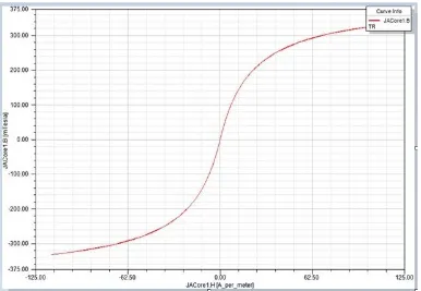
Fig. (2) b-h curve for Rx50-mm diameter single coil inductor
without bias current
Fig: (4) b-h curve of Rx50-mm diameter core with bias current
Fig: (8) shows curve of Rx40-mm core in buck converter with bias current
In the Fig. (2), (3), (4), (5) we can see the Rx50-mm diameter has higher flux capacity when the bias current is flowing. Fig. (6), (7) shows that the optimised core Rx40-mm diameter core has higher flux capacity with bias current. In the Rx40-mm diameter core more current is flowing than the Rx50-mm diameter core. Thus the inductor value increases with bias current.
V. CONCLUSION
Implemented an optimised variable power inductor in a buck converter . A higher current passes through a same core when a negative bias current is applied to the secondary winding. Implemented an optimised core of smaller size with same current flowing capacity as the larger core. In the optimised core also more current passes when a negative bias current is applied to the secondary winding.
REFERENCES
[1] M. Yilmaz and P. T. Krein, “Review of battery charger topologies, charging power levels, infrastructure for plug-in electric and hybrid vehicles,” IEEE Trans. Power Electron., vol. 28, no. 5, pp. 2151–2169, May 2013.
[2] S. Haghbin, S. Lundmark, M. Alakula, and O. Carlson, “Grid-connected integrated battery chargers in vehicle applications: Review and new solution,” IEEE Trans. Ind. Electron., vol. 60, no. 2, pp. 459–473, Feb. 2013.
[3] X. Zhou, S. Lukic, S. Bhattacharya, and A. Huang, “Design and control of grid-connected converter in bi-directional battery charger for plug-in hybrid electric vehicle application,” plug-in Proc. IEEE VPPC, Sep. 2009, pp. 1716–1721.
[4] T. Bhattacharya, V. S. Giri, K. Mathew, and L. Umanand, “Multiphase Bidirectional Flyback Converter Topology for Hybrid Electric Vehicles,” IEEE Trans. Ind. Electron., vol. 56, no. 1, pp. 78–84, Jan. 2009.
[5] S. S. Ahsanuzzaman, T. McRae, M. M. Peretz, and A. Prodic, “Lowvolume buck converter with adaptive inductor core biasing,” in Proc. IEEE APEC, Feb. 5–9, 2012, pp. 335–339.
[6] M. S. Rylko, J. G. Hayes, and M. G. Egan, “Experimental investigation of high-flux density magnetic materials for high-current inductors in hybridelectric vehicle DC–DC converters,” in Proc. IEEE VPPC, Sep. 1–3, 2010, pp. 1–7.
[7] B.-G. You, S.-W. Lee, G.-B. Choi, D.-W. Yoo, and B. Lee, “Comparison of simulation and experimental results for Mega Flux inductors in hybrid electric vehicles,” in Proc. IEEE ICPE ECCE, May 30–Jun. 3, 2011, pp. 1950–1957. [8] H. Kosai et al., “Coupled inductor characterization for a high performance interleaved boost converter,” IEEE Trans. Magn., vol. 45, no. 10, pp. 4812–4815, Oct. 2009.
[9] H. Kosai, J. Scofield, S. McNeal, B. Jordan, and B. Ray, “Design and performance evaluation of a 200 ◦C interleaved boost converter,” IEEE Trans. Power Electron., vol. 28, no. 4, pp. 1691–1699, Apr. 2013.
[10] M. Pavlovsky, G. Guidi, and A. Kawamura, “Assessment of Coupled and Independent Phase Designs of Interleaved Multiphase Buck/Boost DC–DC Converter for EV Power Train,” IEEE Trans. Power Electron., vol. 29, no. 6, pp. 2693–2704, Jun. 2014.
[11] X. Hu and C. Gong, “A high gain input-parallel output-series DC/DC converter with dual coupled inductors,” IEEE Trans. Power Electron., vol. 30, no. 3, pp. 1306–1317, Mar. 2015.