University of Windsor University of Windsor
Scholarship at UWindsor
Scholarship at UWindsor
Electronic Theses and Dissertations Theses, Dissertations, and Major Papers
1-1-2007
Reconfigurable kinematics of General Stewart Platform and
Reconfigurable kinematics of General Stewart Platform and
simulation interface.
simulation interface.
Anqi Wang
University of Windsor
Follow this and additional works at: https://scholar.uwindsor.ca/etd
Recommended Citation Recommended Citation
Wang, Anqi, "Reconfigurable kinematics of General Stewart Platform and simulation interface." (2007). Electronic Theses and Dissertations. 7122.
https://scholar.uwindsor.ca/etd/7122
This online database contains the full-text of PhD dissertations and Masters’ theses of University of Windsor students from 1954 forward. These documents are made available for personal study and research purposes only, in accordance with the Canadian Copyright Act and the Creative Commons license—CC BY-NC-ND (Attribution, Non-Commercial, No Derivative Works). Under this license, works must always be attributed to the copyright holder (original author), cannot be used for any commercial purposes, and may not be altered. Any other use would require the permission of the copyright holder. Students may inquire about withdrawing their dissertation and/or thesis from this database. For additional inquiries, please contact the repository administrator via email
AND SIMULATION INTERFACE
By
Anqi W ang
A Thesis
Subm itted to the Faculty o f G raduate Studies and R esearch
through Industrial Engineering and M anufacturing System s
in Partial Fulfillm ent o f the Requirem ents for
the D egree o f M asters o f Science at the
U niversity o f W indsor
W indsor, O ntario, Canada
1*1
Library and
Archives Canada
Published Heritage
Branch
395 W ellington Street Ottawa ON K 1A 0N 4 Canada
Bibliotheque et
Archives Canada
Direction du
Patrimoine de I'edition
395, rue W ellington Ottawa ON K 1A 0N 4 Canada
Your file Votre reference ISBN: 978-0-494-42313-4 Our file Notre reference ISBN: 978-0-494-42313-4
NOTICE:
The author has granted a non
exclusive license allowing Library
and Archives Canada to reproduce,
publish, archive, preserve, conserve,
communicate to the public by
telecommunication or on the Internet,
loan, distribute and sell theses
worldwide, for commercial or non
commercial purposes, in microform,
paper, electronic and/or any other
formats.
AVIS:
L'auteur a accorde une licence non exclusive
permettant a la Bibliotheque et Archives
Canada de reproduire, publier, archiver,
sauvegarder, conserver, transmettre au public
par telecommunication ou par Nntemet, preter,
distribuer et vendre des theses partout dans
le monde, a des fins commerciales ou autres,
sur support microforme, papier, electronique
et/ou autres formats.
The author retains copyright
ownership and moral rights in
this thesis. Neither the thesis
nor substantial extracts from it
may be printed or otherwise
reproduced without the author's
permission.
L'auteur conserve la propriete du droit d'auteur
et des droits moraux qui protege cette these.
Ni la these ni des extraits substantiels de
celle-ci ne doivent etre imprimes ou autrement
reproduits sans son autorisation.
In compliance with the Canadian
Privacy Act some supporting
forms may have been removed
from this thesis.
While these forms may be included
in the document page count,
their removal does not represent
any loss of content from the
thesis.
Conformement a la loi canadienne
sur la protection de la vie privee,
quelques formulaires secondaires
ont ete enleves de cette these.
Bien que ces formulaires
aient inclus dans la pagination,
il n'y aura aucun contenu manquant.
i*i
Canada
This research introduces a new algorithm to solve the forward kinematics o f the
General Stewart Platform. Basically, there are at least 20 basic feasible topologies for the
General Stewart Platform and many different configurations for each o f them, some o f
which have been studied fully but most o f them have not. The new algorithm can be
extended to solve every single configuration o f General Stewart Platform by slight
change o f inputs. Unlike the existing algorithm, the proposed algorithm was developed
by projective geometry, which enables the extension o f solution to any special
configuration. In addition, extra sensors are introduced to give a set of good initial
estimate in order to solve the nonlinear equations. A clear classification is given to
classify all special Stewart Platforms that can be used in practice.
This research also develops a graphical robotic simulation module to model and
simulate the General Stewart Platforms by creating an optimized object-oriented design
module added to software designed by Ding [Ding, Z.Q., 2005]. The design approach
implements all components in the Visual C++ programming language and freely
distributed graphical library OpenGL, utilizing a single PC running the Windows
operating system. The algorithm and the simulation module are demonstrated by two
ACKNOW LEDGEMENTS
I would like to express my sincerest and deepest appreciation to my supervisor
Professor Waguih ElMaraghy for giving me the opportunity, his guidance, and for
helping me throughout the course o f my M.A.Sc program. I would also like to extend my
thanks to my Supervisory Committee, Dr. Hoda ElMaraghy and Dr. Jonathan Wu for
their comments and time in reviewing my thesis.
Within our excellent UROCA research team, I am very grateful to Ms. Zhongqing
Ding, Ms. Ana M. Djuric and Dr. Yang Cao for their great work. They have helped me
throughout my research and their efforts have let me not only work with my favourite
research topic, but also made my work much easier.
I would like to acknowledge the great help and insight that I received from the IMS
Centre directors, Professor Hoda ElMaraghy and Professor Waguih ElMaraghy, for
giving me the chance to discuss the research topics with other members through the
regular meetings they arranged for us. I learned a lot from these meetings. I would like to
extend my thanks to all other members in IMS Centre for their suggestions and
encouragement.
I would like to thank the Industrial and Manufacturing Systems Engineering
Department staff: Ms. Jacquie Mummery, Mr. Ram Barakat and Ms. Zaina Batal for their
support and kind assistance during my study period.
A BSTRACT...iii
A CK NO W LEDG EM EN TS... iv
TABLE OF C O N T E N T S...v
LIST OF FIG U R E S... vii
LIST OF T A B L E S...ix
CHAPTER I. INTRODUCTION 1.1 Kinematic Geometry o f M echanism s... 1
1.2 Introduction to R obotics...4
1.3 Objectives and Contributions... 13
1.4 Thesis O verview ...15
II. REVIEW OF LITERATURE 2.1 Review o f Kinematics o f Stewart P latform ... 16
2.2 Comparison with the Existing A pproaches... 20
2.3 Review o f Graphical Robotic Simulation S y stem s... 25
III. RECONFIGURABLE KINEMATICS OF STEW ART PLATFORMS 3.1 Reconflgurable Kinematics M od el... 31
3.2 Classification o f Stewart Platform s... 43
3.3 Matlab-based Im plem entation...49
3.4 Applications o f Reconflgurable Kinematics M o d el... 51
IV. SIM ULATION SOFTWARE DESIGN AND IMPLEM ENTATION 4.1 Software background and Design requirem ents... 57
4.2 Software design and im plem entation...58
V. APPLICATION EXAMPLES 5.1 3-3 Stewart Platform s... 70
5.2 5-4 Stewart Platforms (1-2-1-2)...78
VI. CONCLUSION AND FUTURE W ORK 6.1 C onclusion... 84
APPENDICES
SAMPLE MATLAB PR O G RA M ...86
SAMPLE C++ PR O G R A M ...89
USER M ANUAL... 93
REFERENCES...97
VITA A U C T O R IS ...105
F ig u re 1.1: Industrial robots doing vehicle underbody assem bly... 5
F ig u re 1.2: Cincinnati Milacron T Robot A rm ... 6
F igu re 1.3: An example o f Stewart Platform ...9
F ig u re 1.4: Fully parallel Stewart-Gough platform ...10
F ig u re 1.5: Fully parallel HEXA platform; all joints are revolute...10
F igu re 1.6: Milling machine with a parallel manipulator design...12
F ig u re 2.1: Stewart Platform M echanism...16
F igu re 2.2: Stewart Platform with four extra sensors... 22
F ig u re 3.1: The general Stewart platform ... 31
F igu re 3.2: Common Side Condition...34
F ig u re 3.3: 2S Common Diagonal Condition... 36
F ig u re 3.4: 3S Common Diagonal Condition...37
F ig u re 3.5: OS Superposition Condition... 39
F ig u re 3.6: The end-effector position and orientation o f Stewart Platform ... 41
F igu re 3.7: Applications o f Stewart Platform s... 51
F igu re 3.8: 3-3 Stewart Platform ... 52
F ig u re 3.9: 6-3 Stewart Platform ...54
F ig ure 3.10: 6-3Equivalent M echanism... 55
F ig u re 4.1: The M enu Structure o f G U I... 61
F igu re 4.2: The GSP M enu... 61
Figure 4.4: GSP Toolbar Shortcut Buttons...62
Figure 4.5: Moving Reference Coordinate System... 63
Figure 4.6: Overall System Structure...64
Figure 4.7: Parameters Input D ialogs...65
Figure 4.8: The Overall Coordinate Systems...66
Figure 4.9: Pendent View D ialog... 68
Figure 4.10: Learn Pose Points V iew ...69
Figure 5.1: 3-3 Stewart Platform ... 70
Figure 5.2: Kinematic Model o f 3-3 Stewart Platform... 71
Figure 5.3: Parameters Input o f 3-3 Stewart Platform ... 76
Figure 5.4: The Inputs o f Target Points(3-3SP)... 77
Figure 5.5: The Simulation Path(3-3SP)... 77
Figure 5.6: Kinematic Model o f 3-3 Stewart Platform (5-4SP)... 78
Figure 5.7: The Simulation Path(5-4SP)... 83
T able 2.1: Matrix o f Critical Literature Review...23
T able 3.1: Hexagon Base Topologies... 44
T able 3.2: Pentagon Base Topologies... 46
T able 3.3: Quadrangle Base Topologies... 47
T able 3.4: Triangle Base Topologies... 49
T able 5.1: The Definition o f Target Points(3-3 SP)...76
1
CHAPTER I
INTRODUCTION
This chapter presents an introduction to the principal concepts and technologies
involved throughout this research. The first section introduces kinematic geometry o f
mechanisms. In the second section some basic topics regarding to robotics are introduced.
The third section overviews existing kinematics solving methods and graphical robotic
simulation systems, with emphasis on their characteristics. Through this, the motivation
for proposing a new algorithm and developing a unified robotic kinematic simulation
interface is explained. The objectives o f this research are also described at the same time.
Finally, the fourth section presents an overview o f this thesis.
1.1 Kinematic Geometry o f Mechanisms
Basic geometry was developed by the ancient Greeks and Euclid’s Elements was
written as early as 300 BC. The foundations o f algebra as we know it, on the other hand,
were laid down much later— in the third century AD— and it was only after the
development o f calculus in the 17th century that the analytical study o f mechanics
became possible. The arguable preference o f the algebraic over the geometric approach is
not an issue o f the past. The recent advent o f the computer brought a revolution in
mechanical design. While certainly the computer proved to be o f great assistance to the
engineer, it has also had negative effects on the readiness to seek deeper understanding o f
the principles o f mechanical motion. This trend was quickly noticed and eloquently
described by the two most famous advocates o f kinematic geometry: [Joyce, D.E., 1997]
1
With a computer at his elbow an engineer is often tempted to pay little if any
attention to principles, but rather plunge into a particular problem o f synthesis without
considering either the fundamental theory or the criteria that limit the performance o f the
devices he aims to produce. But more importantly the geometric principles reveal a map
o f a terrain, regions within which can then be explored in greater detail by analytical or
graphical methods. I f the map shows that there are inaccessible regions on the terrain, if it
warns o f hazards and dangerous frontiers, and if it can guide the explorer along safe paths
by which he can reach his goal quickly with simple transport, then it should have some
value [Hunt, K.H., 1978].
The digital computer demands on the part o f its machine-designing users a ruthless
competence in the algebraic processes needed for the manipulation o f mechanical
information and its numerical analysis. It is accordingly fashionable ju st now in the field
of the theory o f machines not so much to denigrate as simply to ignore the main bases in
actual mechanical motion from which these algebraic processes grow. The main bases are
essentially pictorial, geometrical. They arise from natural philosophy. Students in the
mechanical sciences are becoming increasingly unable to contemplate a piece o f ordinary
reality in machinery accordingly, and to extract from that reality the geometric essence o f
it. It is o f course true that without algebra there can be no programme, no numerical data,
and no numerical result; but without an underlying geometry o f the reality there can be no
applicable algebra. W ithout a diagram w e cannot write an equation. B ut w ithout geom etry
So well have Profs. Kenneth Hunt and Jack Phillips warned against the treacherous
trend o f over-dependence on computer-based solutions. While the powerful programs for
symbolic computations are undoubtedly helpful in design, they should be used only with
complete understanding o f their limitations (e.g., when dealing with trigonometric
expressions). Paradoxically, it is exactly the development o f the com puter that has made
geometry important again. As computers and automatic control algorithms have become
more powerful, designs o f increasingly complicated mechanisms have become practical.
If prior to that, analytic methods were sufficient for the study o f mechanisms, this was
because these mechanisms were o f outstanding simplicity. However, the complex spatial
machines o f nowadays can no longer be completely analysed by purely analytic or
numerical methods. While most researchers were occupied developing or using
computer-aided engineering tools, the two Australian professors, Kenneth Hunt and Jack
Phillips, were among the few who realised the need for a revival o f the geometric
methods.
Kinematic geometry is the first and simplest segment o f kinematics that deals
exclusively with displacements. [Hunt, K.H., 1978] Time, as a variable, is usually not
required to be brought into account. Indeed, the use o f screw theory eliminates that need
completely. Yet for convenience, velocity may sometimes be introduced in the study of
the special, so-called singular, configurations o f mechanisms. The main subject o f this
research is the p osition kinem atics o f parallel m echanism s or the geom etry o f tw o
relatively moving bodies connected by a multitude o f kinematic chains.
3
1.2 Introduction to Robotics
The Robot Institute o f America defined that “a robot is a reprogrammable
multifunctional manipulator designed to move materials, parts, tools or specialized
devices through variable programmed motions for the performance o f a variety o f tasks”.
Robotics is concerned with the study o f those machines that can replace human
beings in the execution o f a task with regards to both physical activity and decision
making. Robotics is truly a multidisciplinary field that includes mechanical and electronic
engineering, computer science, and mathematics.
1.2.1 Introduction to Industrial Robots
An industrial robot is officially defined by ISO as an automatically controlled,
reprogrammable, multipurpose manipulator programmable in three or more axes. The
field o f industrial robotics may be more practically defined as the study, design and use of
robot systems for manufacturing.
Typical applications of industrial robots include welding, painting, ironing, assembly,
pick and place, palletizing, product inspection, and testing, all accomplished with high
5
Figure 1.1: Industrial robots doing vehicle underbody assembly (KUKA).
[Wikipedia, http://en.wikipedia.org/wiki/Industrial robotl
An industrial robot consists of:
A manipulator
4- Actuators
❖ Sensors
A control system.
5
Elbow extension
Shoulder swivel
A rm
WriM
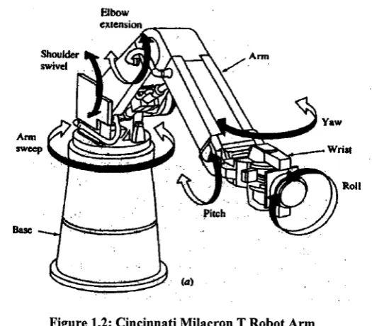
Figure 1.2: Cincinnati Milacron T Robot Arm
[RISC lab, http://wwwlbpt.bridgeport.edu/~sobh/html/proj/sanjeev/project.html]
A manipulator or mechanical structure consists o f a sequence o f rigid links
connected by revolute or prismatic joints. Figure 1.2 illustrates an industrial robot
manipulator. A manipulator has a supporting base, an arm that ensures mobility, a wrist
that confers dexterity, and an end-effector that performs the desired task. The motion o f
the joints results in the relative motion o f links.
1.2.2 Introduction to Parallel mechanism
The geometric approach used in this research has a wide application. Apart from
Stewart Platforms, the approach may also be applied to the study o f other parallel robots,
to computer animation, and to many other fields. The field o f parallel robots, despite the
scarcity o f specialised textbooks, is already too advanced to allow us to review it on a
7
we suggest a visit to the on-line Parallel Mechanisms Information Center at
http ://www .par allemic. or g.
An n-DOF (n-degree-of-freedom) fully-parallel mechanism is composed o f n
independent legs connecting the mobile platform to the base. Each o f these legs is a serial
kinematic chain that hosts one and only one motor which actuates, directly or indirectly,
one o f the joints. The variables that describe the actuated joints will be referred to as the
input variables or also as the active joint variables. Other authors refer to the same
variables as articular coordinates. On the other hand, the variables that describe fully the
pose o f the mobile platform (the end-effector) will be referred to as output variables. In
other works, the same variables are referred to as generalised coordinates.
The configuration o f an n-DOF parallel mechanism is not defined by its input
variables. The task o f finding the valid set of output variables corresponding to a set o f
input variables, referred to as the direct kinematic problem, has usually a multitude o f
solutions, referred to as assembly modes. In fact, some mechanisms allow an infinite
number o f solutions to their direct kinematics— a situation referred to as self motion
[Karger, A., 1996]. M ore precisely, self motion means a finite mobility from some points
o f the workspace, whereas the confusingly similar term architecture singularity refers to a
singularity in every point o f the workspace [Ma, O., 1992]. W hen two, or more, o f the
assembly modes are coinciding, w e say that there is a T ype 2 singularity. The
configuration o f an n-DOF parallel mechanism is not even defined by both the input and
output variables. Indeed, some mechanisms exist which will allow passive motion even
when the motors and the mobile platform are fixed. Such particular singularities are
7
frequently, however, the user and the designer o f a parallel mechanism will be interested
only in the set o f feasible output variables which we will refer to as the complete
workspace. The complete workspace o f a 6-DOF parallel manipulator is a six
dimensional highly coupled entity which is practically impossible to visualise. Therefore,
the complete workspace o f such mechanisms is studied only through its different subsets.
M ost o f these are also defined for parallel mechanisms with less than six degrees o f
freedom. The most common subset o f the complete workspace is the constant-orientation
workspace which is the set o f permissible positions for the centre o f the mobile platform
while the platform is kept at a constant orientation. Conversely, the orientation workspace
is the set o f permissible orientations o f the mobile platform, while the platform centre is
held fixed.
1.2.3 Introduction to Stewart-Gough Platform
A Stewart platform is a kind o f manipulator using an octahedral assembly o f struts.
A Stewart platform has six degrees o f freedom (x, y, z, pitch, roll, & yaw). There are six
independently actuated legs, where the lengths o f the legs are changed to position and
orient the platform. The forward kinematics problem, an equation which given the leg
lengths, finds the position and orientation o f the platform, has 16 solutions. However, the
the inverse kinematics problem (i.e. given the position and orientation o f the platform,
Stewart platforms have applications in machine tool technology, crane technology,
underwater research, air-to-sea rescue, flight simulation, satellite dish positioning, aircraft
simulators and telescopes.
James S. Albus o f the National Institute o f Standards and Technology (NIST) has
developed a crane, known as RoboCrane® [Albus, J.S., 1993], which uses the Stewart
platform technology. Geodetic Technology trademarked "hexapod" for a Stewart platform
in a machine tool context.
The Stewart platform was first reported in a paper by V. E. Gough in 1956 [Gough,
V.E., 1956]. The name o f Stewart was attached to this architecture because Gough's
earlier work (and a photograph o f his platform) was mentioned in the reviewers' remarks
to a paper by D. Stewart published in 1965 [Stewart, D., 1965]; in that paper, Stewart
presents another hybrid design, with three legs having two motors each.
Figure 1.3: An example of Stewart Platform
[Wikipedia, http://en.wikipedia.org/wiki/Stewart_platform]
9
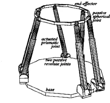
1.2.4 Introduction to Kinematics o f Parallel Robots
This section describes the kinematics o f parallel robots, i.e., robots whose base and
end-effector are connected by multiple serial chains in which not all joints are actuated. A
fully parallel robot has six serial chains in parallel, and only one joint in each chain is
actuated (Figure 1.4). O f course, all sorts o f combinations o f these purely serial and
parallel structures are possible, and many exist in practice.
md'iffector
passive
spherical
‘-'ini
actuated
prism tiic joint
o missive
revaiuie joints
Figure 1.4: Fully parallel Stewart-Gough platform;
[Bruyninckx, H., 2005, Parallel Robots, http://www.roble.info/robotics/paraIIel/]
base'^
active revolute, jo in t passive Hook
joint
' / / passive sphericc,
’ jo in t
■'end-effector
Figure 1.5: Fully parallel HEXA platform; all joints are revolute.
11
The main reasons for the overwhelming success o f the serial robot design (over 99%
o f installed industrial robots) is that: It gives a large workspace compared to the space
occupied by the robot itself; Kinematic designs exist that simplify the mathematics o f the
robot’s geometry enormously.
The main drawback o f a serial design is its low intrinsic rigidity, so that heavy links
and joints must be used to obtain a reasonable effective rigidity at the end point. These
pros and cons are exactly the opposites o f those of parallel manipulators. The fully
parallel designs o f robots (Figure 1.5) have all actuators in or near the bases, which result
in a very low inertia o f the part o f the robot that has actually to be moved. Hence, a higher
bandwidth can be achieved with the same actuation power. This is why parallel structures
are used for, for example, flight simulators and fast pick-and-place robots. A parallel
structure supports its end-effector in multiple places, which yields a stiffer and hence
more accurate manipulator for the same weight and cost, and which causes the
positioning errors generated in each leg to “average out,” again increasing the accuracy.
This would be very advantageous for accurate milling (Figure 1.6). This pioneer was very
unsuccessful in the marketplace. However, experiments with real prototypes show that
parallel structures currently do not live up to these expectations: their accuracy and
stiffness are about an order o f magnitude worse than for classical serial machines. The
reasons are:
The compliance o f the ball screws in the prismatic joints;
The complexity o f the construction with many passive joints that all have to be
manufactured and assembled with strict tolerances;
11
The complexity o f kinematic calibration o f this structure;
The high forces that some passive joints have to resist.
In addition, another major disadvantage o f parallel manipulators is their small
workspace: legs can collide, and there are many passive joints in the structure that all
introduce joint limit constraints. This is especially the case with the spherical “ball-in-
socket” joints used in most implementations [Merlet, J.-P., 2006].
Figure 1.6: Milling machine with a parallel manipulator design
The definitions o f forward and inverse position and velocity kinematics as defined
for serial robots apply to parallel robots without change. But parallel robots have a large
number o f passive joints, whose only function is to provide the required number of
degrees o f freedom to each leg. Adding a leg between end-effector and base adds motion
constraints to the end-effector, while in the case o f serial robots adding a joint reduces the
motion constraints (or, equivalently, adds a motion degree o f freedom). This text
discusses six degrees o f freedom robots only, but many designs have less than six, e.g.,
13
1.3 Objectives and Contributions
Reconflgurable Kinematics o f GSP
Most o f researches nowadays are only focused on one specific or several similar
Stewart Platforms. The algorithms they proposed are mostly Platform-Specific. An
algorithm that can solve all the special cases o f General Stewart Platform will make the
analysis o f GSP kinematics easier a lot and it also will make the software programming o f
GSP simulation possible. And the reconflgurable kinematics can help to pick up a best
topology for a specific application as well.
General Stewart Platform Simulation
A number o f simulation software has been programmed to implement simulation o f
one or more particular platforms or products. If this simulation can be extended to general
case it will be a great help for robot producers and researchers. So the development o f a
GUI, which provides 3D GSP kinematics modeling and simulation, is necessary. Our
main objectives consist o f the following two parts:
Develop an algorithm to solve general Stewart Platforms
U tilizin g the geom etrical sim ilarity o f all different Stewart Platform , w e can develop
an algorithm with 6 variables (Struts’ lengths) and 12 inputs (links’ parameters) to solve
general Stewart Platforms with slight changes o f inputs.
13
Create software to simulate general Stewart Platforms
Create a programming strategy to embed the GUI o f GSP simulation to our UROCA
6DOF serial robot simulation software. Design the GUI o f GSP simulation based on the
model developed in our first objective. Build DLLs to solve kinematics automatically and
implement the GSP simulation.
Contributions
In the past 40 years, much research and innovation has been made to parallel robots,
their kinematics and simulation. M ost o f the improvements were focused on some special
topologies, which have simpler structures or special characteristics making the real-time
calculation o f forward kinematics possible. The Stewart Platforms are the most widely
used parallel mechanisms and they have most o f the advantages o f parallel mechanisms
compared with serial robots and relatively simple structures.
In this research, the improvements have been made consist o f two main parts, a new
algorithm that can solve forward kinematics o f General Stewart Platform and an upgraded
software with the simulation function o f General Stewart Platforms. In addition, a clear
classification has been made to classify all special topologies o f Stewart Platforms that
15
1.4 Thesis Overview
Chapter 1 provides an introduction to kinematic geometry, robotics, robotic
kinematics, simulation platform, as well as the main technologies involved. Then the
motivation and objectives o f this research are presented.
Chapter 2 provides a systematic literature review, which consists o f two parts,
review o f Stewart Platform Kinematics and review o f Graphical Robotic Simulation
System.
In Chapter 3, the details o f the proposed algorithm for reconflgurable kinematics of
General Stewart Platforms are introduced along with the Matlab implementation and the
illustration o f reconflgurable kinematics applications. Meantime, a clear classification o f
Stewart Platforms is proposed.
Chapter 4 introduces the software design procedure and illustrates software structure
o f the GUI, its main functions and an explanation o f software implementation based on
the theories in Chapter 1 previously.
Application examples are provided in Chapter 5 to illustrate the application of
algorithm to a special to p olo gy and the sim ulation procedure.
The conclusion and future research are given in Chapter 6.
15
CHAPTER II
REVIEW OF LITERATURE
2.1 Review o f Kinematics o f Stewart Platform
The purpose o f using flight simulators while training pilots is to minimize training
losses and training time. A parallel mechanism placed under the simulator provides the
translational and rotational movements that the pilot would be exposed to when flying
with a real aircraft. Stewart was the first to bring up the idea o f using parallel
mechanisms in flight simulators [Stewart, D., 1965]. In the following years, parallel
mechanisms have started being used commonly in various areas such as oil platforms and
robotics.
Vito
A3
82
17
Parallel mechanisms are kinematic chains with one or more closed loops and with
actuators moving one or more o f their links. Stewart Platform M echanism (SPM), the
most renowned parallel mechanism, consists o f a fixed base platform and a movable
platform, linked by 6 legs whose lengths can be changed via actuators on the base.
[Figure 2.1]
The top platform has 6 degrees o f freedom (DOF) o f motion with respect to the base.
If the legs are appointed certain fixed lengths, then the mechanism becomes a structure
[Ku, D., 1999]. Traditional industrial robots are open-loop mechanisms with serial chains.
Although serial chains reach further and have larger workspaces than parallel ones,
parallel mechanisms have better dynamic characteristics. Serial mechanisms are not as
rigid as parallel ones and have lower natural frequencies. Additionally, each link, starting
from the one fixed to the base, until the tip link, must both be large enough to carry the
preceding ones and provide the required accuracy. Another disadvantage o f serial chains
is that actuator errors add to one another, resulting in a huge error at the tip. Parallel
mechanisms are preferred in applications where dynamic loading is high, speed and
accuracy are important, and workspace volume is o f less importance. In contrast to serial
chains, not all the links are set into motion by the actuators, and moving parts are lighter,
since the actuators are fixed to the base.
D u e to their com m on application in aircraft simulators, a lot o f work has been
conducted on the SPM. M ost often, one o f the joints linking the legs to the platforms is a
spherical jo int while the other is a universal joint. Nomenclature o f the SPM is done
17
according to its jo in t types and the number o f links the SPM has. Even though there exist
many papers in the literature on 3-3, 6-6 and 6-3 mechanisms, some researchers have
come up w ith their own mechanism architectures in order to optimize certain criterion
[Stoughton, R. S., and Arai, T., 1993].
The forward kinematics problem o f the SPM is to determine the position and
orientation o f the top platform with respect to the base, when leg lengths are known. The
inverse kinematics problem is to solve for the leg lengths that will result in a given
position and orientation o f the top platform. The forward kinematics problem has more
than one solution, whereas the inverse kinematics problem has a single solution. Inverse
kinematics has to be solved online for real-time trajectory tracking, and forward
kinematics must be solved for real time control o f the SPM [Innocenti, C., and Parenti-
Castelli, V., 1990],
Lee and Shah [Lee, K. and Shah, D.K., 1988], who have shown that 6-dof parallel
mechanisms can be composed by linking 3-dof mechanisms, have done the forward and
inverse kinematic analysis o f a 3-dof parallel mechanism. Nanua et al [Nanua, P.,
Waldron, K.J., and Murthy, V., 1990], have solved the forward kinematics problem o f 6-
3 SPM, reaching a 16th order polynomial, meaning the top platform can have 16 different
configurations for a given set o f leg lengths. Innocenti and Parenti-Castelli [Innocenti, C.,
and Parenti-Castelli, V ., 1990], have solved the forward kinem atics problem o f the
general SPM in closed form, repeating that the problem has 16 different solutions.
spherical SPM, concluding that the problem has 16 solutions. Shi and Fenton [Shi, X. ve
Fenton, R.G., 1992] have worked on the instantaeous kinematics o f the SPM, resulting in
6 linear equations. M erlet [Merlet, J. P., 1993] has solved the forward kinematics o f
parallel mechanism in 4 different ways, and compared them on the grounds o f
computational time. Three o f these methods are iterative methods and the fourth is the
polynomial method. Although the computational time o f the polynomial method is one
order o f magnitude greater than that o f the other three, it is the only method that gives all
solutions.
It must be kept in mind that not all o f the solutions o f the forward kinematics
problem are physically feasible. When leg length constraints, join t rotation constraints
and leg interference are taken into consideration, it will be seen that out o f the 16
solutions o f the forward kinematics problem, only 12 are feasible solutions [Yurt, S. N.,
2002]. Liu et al [Liu, K., Fitzgerald, J. M., and Lewis, F. L., 1993] has put the forward
kinematics problem o f the SPM in the form o f three nonlinear equations, which can only
be solved by numerical schemes. With the method proposed in this work, the difficulty of
solving a 16th order polynomial no longer exists. Sreenivasan, Husty and Innocenti
[Sreenivasan, S.V., Waldron, K.J., and Nanua, P., 1994][Husty, M. L., 1996][Innocenti,
C., 1998] have solved the forward kinematics problem o f the 6-6 SPM using closed-form
algebraic equations. Dasgupta and Mruthyunjaya [Dasgupta, B. and Mruthyunjaya, T.S.,
1994] have solved the very sam e problem in canonic form. K u [Ku, D ., 1999] has solved
the kinematics equations o f the octahedral SPM that Nanua derived, using a simple and
computationally efficient method based on Newton-Raphson’s method. The aim o f that
19
work was to reduce the computational effort that the polynomial method requires.
Jakobovic and Jelenkovi [Jakobovic, D. and Jelenkovic, L., 2002] have stated that the
forward kinematics problem can also be solved via optimization algorithms and that the
solution converges when errors are allowed to be o f the order o f 10-12 times leg lengths.
In addition to the general SPM, there has been work done on mechanisms with
special architectures. For example, Nanua [Nanua, P., Waldron, K.J., and Murthy, V.,
1990] has solved the forward kinematics o f 3-6/3-3 Stewart Platform. Tsai [Tsai, M. S.,
2003] have solved the forward kinematics o f the 3-PRS mechanism, while Kim and Park
[Kim, J. and Park, F. C., 2001] have solved the forward kinematics o f the 3-RS parallel
mechanism., Di Gregorio [Di Gregorio, R., 2001] has solved the forward kinematics of
the 3-URC wrist, Carretero [Carretero, J. A., 2000] has solved the forward and inverse
kinematics o f the 3-PRS mechanism, and Callegari and Tarantini [Callegari, M. and
Tarantini, M., 2003] has solved the forward and inverse kinematics o f the 3-RPC. Di
Gregorio [Di Gregorio, R., 2002] has made proposals on purely translational parallel
mechanisms, however they can not be used as flight simulators since they cannot
simulate motion in six directions, meaning translation in three dimensions and rotation in
three dimensions.
2.2 Comparison with the Existing Approaches
Basically, there are three approaches that are adopted to solve the forward
kinematics o f parallel robots, and they are univariate polynomial equation method,
21
univariate polynomial equation method is the only one that is able to solve the kinematics
completely and get all the solutions for the forward kinematics but unfortunately there is
no way to determine which solution is the current pose o f the parallel robot. For
numerical iterative method, there is no guarantee that the iteration is convergent. In the
latest 10 years, the extra sensors method was proposed and implemented in researches
and practice uses. The advantage o f this method is that the forward kinematics can be
obtained in short time without high performance computer required. This is the only
method that can be used for real time applications. In the following three paragraphs, a
brief introduction o f these methods will be given [Karger, A., 1996] [Merlet, J.-P., 2006].
Univariate polynomial equation method is to obtain a polynomial equation with a
single variable by using some algebraic eliminating methods or geometrical eliminating
methods so that the maximal number o f solution can be easily told. It is worth noting that
this study was started by Nanua and Waldron who determined a 24th order polynomial
for the MSSM system [Nanua, P., Waldron, K.J., 1990][Husty, M. L., 1996][Innocenti,
C., 1998][Wang, T. and Chen, C. C., 1993],
Numerical iterative method is to use numerical approaches to solve forward
kinematics directly. The computation time is rather large and the convergence is not
guaranteed; there is the problem o f sorting the current pose from all the possible solutions,
w hich has never been studied so far because o f its com plexity. W e need a numerical
method that produces the right solution in a reasonable time. All we concern are the
methods efficiency and convergence. The drawback is that the obtained solution is not
21
necessarily the solution closest to the initial estimation, which will be the most likely the
current pose o f the end-effector [Huang, M.Z., 1996][Wang, T. and Chen, C. C., 1993].
Solving direct kinematics with extra sensors is adding extra sensors to the non
actuated joints to obtain information allowing fast calculation o f the forward kinematics.
What type o f the extra sensors? Where are they placed? How many extra sensors the
system needs? Rotation sensors are usually mounted on the base to avoid increasing
moving platform weight. I f three links are instrumented, which means adding six sensors,
we are able to calculate the position o f three points o f the platform and hence solve the
forward kinematics directly. Six sensors are enough to determine the pose o f the moving
platform by themselves [Bonev, I. A. and Ryu, J., 2000]. However it can be proved that
only four extra sensors are necessary to determine the position and orientation o f the end-
effector. The difference here is that we still need equations to solve that unique solution
according to the extra inputs from four extra sensors. The proof is illustrated by figure 2.2.
23
If two rotation sensors are instrumented on both B1 and B2 joints the position and
orientation o f A1 and A2 on the platform is determined. Let us pick up one o f the left
joints on the moving platform, for example A5. Apparently, it has to be following the
trajectory o f a circle C l, which is perpendicular to the fixed line A1A2 with the radius
A5P1. At the same time, since the points PI and the B5 are both fixed the point A5
should also follows the trajectory o f the circle C2 perpendicular to the line P1B5 and the
radius is A5P2, whose length is also fixed. Obviously the circles C l and C2 can only has
one single common point so actually the joint A5 is determined. The same theory applies
to the rest joints on the moving platform. Hence the forward kinematics o f Stewart
Platform can be determined by four extra-sensors installed on tw o joints on base with 2-2
arrangement.
Table 2.1: Matrix of Critical Literature Review
Ref. Objective Robot Type
Model Developing Methodology
Solution Fields O f Technique Applications
Bonev, J., 2000
Nanua, P., 1990
Solving;* ?
Forward/l-*siS k t i c| pro b lem l'.
kinematics
6-6 S t e w a r t .
planar*mpym‘g
§te»;arS :h.: PJatforrrt^viJh. p ia n a y ja s e - ^ and platform
fjiree. linear ■ extra seosorson e x © | S i y f e S
S I
fr*-. 'Hit- ‘ S b f f e - S S f c-•"££■ V
itt
23
Husty, M.L. 1996
S6jvin^-~
. f . V € * ‘ >
f e i ' r j ; "
-k in em a tics
*
* » ■
-Innocenti, C., 1998
I
.if- +%
" * * ■ *
,
uociem t
6-6, Slew art r m « W-jW-'V: ■ | | |
■fe k -
i-mf '1’, *;* .XL 4R-»w
M H r r •••-•'
■vi ■
S.-*"
RIatTorm'^.':: ci,
f >-3.; :A-.,-.s
■‘J £ . 'T - t
Spatial -■.. .; <jpematic-£ m a p p i n g v '; ^ ; map t h r e c ^ ' 1^
motions
intd^'::?.-dinKn'sionak.^f
itrfege^spaca!,-:-^■ r:
v s llutiOJ
Ut nxvari
Undecided
Numerical ■■ ^ o | ^ | lJy;fcap|b.e a e ra tiv ^ ,!;
m
it^ g e n c M s
[1. *
rcquirea Wang, T.,
1993
Solving;
V-i-v * ryrw aiid..
■ tT i> *■ •
-G eneral^ rC Parallel
JE-—■»* *
-' i «
..Hi A ’
- r. 'Jf VV •■ill
— n — , _____ _ J ^ P l i
* . ■ ' ■ ■
r. stf C -j .'
• - -1* » '=•= ^
■ J . A -■'E -™.:.
,-. » .«<; . -r*fc;!■.'« ■*
■s;--.-; -J
A cut-points : inctliod: use. the dep|h first. ^ ^
S* 2 . \
search
k inem atic graph of-the ro b o '1"
Lee, T.
Y .2001 • I I P "
-joints.
— r * * I - *
, i » * ' ■ * * ■ '
<-¥“r !* **
«. . j*i 1 M
. *'■ '«> 5
V < ' ■ » 4 ,,
My thesis
^ m a t i c s '
if'flY
■-Si-.if * ■
E ia W r n lj; '
•p.v :* t.|
*»#■ -S^'«ST.1811, ■*»* o
nning^ '«! ■' ftK
a-set
V i e t o ^ : ^ am |H im Sic:u/;^
Z - d t ^ ■...‘S' *
' - a f . * '
?:v i ;
■':.£vr : Vr;.
' »J< ■-'■ «
G e om e trical-.
N4ethod '-i.--.' /f,,,
#$3$
25
The comparison Matrix [Table 2.1] below illustrates the advantages and
disadvantages o f different methods adopted to solve the forward kinematics o f Stewart
Platform. M ost o f research are focused on the platforms with six joints and three joints on
the base so that most o f Stewart Platforms with five and four joints on the base are not
discussed before. I mark all these unsolved topologies with “N o solution in published
papers” in the category tables[3.1-3.4], including 6-4(2), 5-4(2), 5-3, 5-2, 4-4(2), 4-4(3),
4-3 and 4-2.
2.3 Review o f Graphical Robotic Simulation Systems
Graphical robotic simulation and off-line programming o f industrial robots are today
relatively mature technologies. Robotic simulation software plays an important role in
robotics research in many areas such as robot design, forward and inverse kinematics
analysis, dynamics, control, path planning, etc. for both commercial and educational
purposes. There are a lot o f graphical robotic simulation software packages available in
the market. Within this chapter, first, the common functionality implemented in the
graphical robotic simulation software packages is described. Second, a literature review
of these packages classified according to their control systems is presented. Meanwhile,
characteristic analyses are provided for each category to summarize the discussed
literature. Finally, the theories and technologies for developing a graphical robotic
simulation system are explained.
25
Grasp2000 rBYG Systems Ltdl. invented by BYG systems Ltd, is a true 3D
simulation tool, based on accurate 3D geometry, process parameters and a library o f
industrial robots. Grasp2000 enables the creation o f accurate 3D models, and real-time
interactive simulations for cell layout design, planning, optimisation, and cycle time
calculation. As a tool for off-line programming, the instructions can be automatically
translated into the required native robot language.
Grasp2000 can generate specific application menus for arc welding, palletising and
spraying. The software will find applications in PC-based cell layout and design, analysis,
offline programming and process planning throughout the full range o f Toshiba SCARA
robot applications.
An important factor in off-line programming is the presence o f inherent inaccuracies
in most robots. Grasp2000 uses in-depth mathematical calculations to calibrate both the
robot and 3D model to match the real world. It only requires the demonstration o f a
number o f robot poses, which are then read into Grasp2000 and analyzed by the
calibration software without external measuring equipment. An optional module for
discrete event simulation extends Grasp2000's application areas to factory simulation,
warehousing, logistics and materials handling.
C S R f A pplied Com puting & Engineering Ltdl. is pow erful 3D sim ulation software
which enables manufacturing engineers to quickly simulate and evaluate automation
27
Using existing in-house CAD data and AC&E's library o f commercial robots and
accessories to create a detailed simulation o f the proposed manufacturing system, CSR
accurately simulates interactions between work cell components to optimize equipment
selection, fine-tune equipment positioning, and maximize production throughput.
The system is the most comprehensive and easy-to-use robotic simulation tool
available and works completely off-line, eliminating the risk o f damage to equipment and
freeing robots for round-the-clock production. CSR can be purchased in a modular
fashion to suit all budgets. Specialized application solutions tailored to the requirements
o f a particular robotic task provide advanced functionality and ease o f use for painting,
spot welding, arc welding, polishing, assembly and press operations.
In tera ctiv e G rap h ics R obot In stru ctio n P ro g ram (IG R IP ) owned by rPELM'IA
Corporation], is an interactive, 3D graphic simulation tool for designing, evaluating, and
off-line programming robotic work cells. Actual robotic/device geometry, motion
attributes, kinematics, dynamics, and I/O logic are incorporated to produce extremely
accurate simulations. IGRIP optimizes critical factors such as robot motion planning,
cycle time prediction, collision detection, calibration, and multiple I/O communication.
The several specific task software modules consist o f UltraArc, UltraSpot,
UltraPaint, and UltraFinishing, which are designed specially for arc welding, spot
w eld ing, painting, and surface finishing work cell applications respectively. Other
applications include research and development, articulated design, flexible manufacturing
system simulation, nuclear/hazardous duty automation, and general-purpose simulation.
27
Work cell components can be created in the integral CAD package or imported from
other CAD packages via IGES, DXF, and direct translators. A built-in surface modeling
package provides modification and/or optimization o f imported surface data.
EA SY -RO B [Anton, S., 2001], 3D Robot Simulation Tool was written in Visual
C++ under the Windows operating system. In order to create high quality and high speed
rendered images, the graphical capabilities o f OpenGL are used. EASY-ROB is a
complex and comprehensive modeling and simulation tool. It is especially designed to
fulfill requirements for several industrial robotic applications as well as for educational
purposes.
The EASY-ROB Basic Model allows the planning and designing o f robotic work
cell layouts consisting o f a robot, tool and environment. A simple 3D CAD system is
provided to create basic geometric parameterized primitives like cubes, cones, cylinders,
pyramids, etc. In addition, a CAD interface is available to import other 3D formats such
as STL. Created and imported geometries are assigned to the robot group to active or
passive joints, to the tool group or to the environment group. Using a 3 button mouse,
each geometry can be translated and rotated about its axis, or the operator can enter
absolute or relative Cartesian values to set the Cartesian location. A modification o f the
view point (pan, tilt, zoom in and zoom out) in full shaded mode allows various world
29
The robot motion can be programmed using EASY-ROB standard program
commands. A special Teach Window supports the user in writing robot motion programs.
The built-in motion planner is implemented for the motion types, Point to point (PTP),
Linear (LIN) and Circular (CIRC). The orientation interpolation for the LIN and CIRC
motion type is realized for variable, fixed, tangential and quaternion modes. Several on
line output windows allow the operator to monitor robot jo int values, Cartesian TCP
location as well as simulation states such as cycle time, step size, override, etc. All data is
saved into documented ASCII text files.
W orksp ace fFlow software technologies!, described in [Owens, J., 1994], has been
developed by a team led by John Owens as the w orld’s first industrial robot simulation
software package commercially released in 1989, and continuously updated over the last
decade.
In addition to a library over 140 industrial robot 3D models available to the user, the
3D CAD modeler can create 3D solid objects using Constructive Solid Geometry and
surface objects such as Bspline, Parametric, and Bezier surfaces. The 3D objects also can
be imported from other CAD system via SXF or IGES file formats. The movement o f any
mechanism may be modeled using a kinematics modeler. The mechanism may have any
number o f joints in any serial or tree-structure combination. Conveyors, automatic
veh icle, and other independently m ovin g objects m ay also be m odeled. Positions and
paths for the robot tool to move to may be defined in several ways such as by use o f the
teach pendant, by clicking the mouse on the screen, or by using geometry points.
29
example, users o f Fanuc robots may write robot programs in Karel, ABB robot users may
write programs in ARLA, or Visual Basic can be used ju st for simulation. Therefore,
there is no need for translating simulation language to robot language. It is also possible
to transfer existing robot programs from the robot control to W orkspace for optimization.
In addition, the simulation can be replayed in real time. Calibration and dynamics
31
CHAPTER III
RECONFIGURABLE KINEMATICS OF STEW ART PLATFORMS
3.1 Reconfigurable Kinematics Model
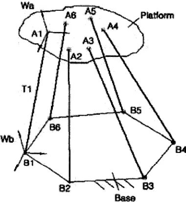
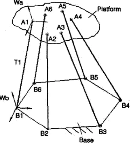
With reference to figure 3.1, input data to the forward kinematics o f the general
Stewart platform are the coordinates o f the base attachment points Bi (i= l, . . . ,6) with
respect to a reference frame Wb fixed to the base, the coordinates o f the platform
attachment points Ai (i= l, . . . ,6) with respect to a reference frame Wa fixed to the
platform, and the actuator lengths Ti (i= l, . . . ,6). Without loss o f generality, the origins
o f reference frames Wb and Wa are chosen at points B l and A l respectively.
Platform Wa
Wb
B4
Base
Figure 3.1: The general Stewart platform
31
3.1.1 Reconfigurable Forward Kinematics
Based on the above defined inputs, we can get the follow list o f inputs for the
convenience o f developing the kinematics model.
Inputs (i= l,2 ,...,6 ) (Linkparam eters)
Base parameters: hexagon
Length o f sides: Bi
Angles: 0 i
“v* Moving platform parameters: hexagon
Length o f sides: Ai
Angles: a i
Length o f struts: (actuated parameters): Ti
And the variables using in our model are two types o f parameters which together
determine the position and orientation o f the platform.
Variables (i= l,2 ,...,6 ) (End effector’s position and orientation);
The length o f struts’ projection on base-plane P i;
A Y i : The angles between pi and Li on the base-plane.
The geometric-based approach we are using to solve the general Stewart Platform
(vertex) on moving platform is used as an intermediate point and the distance between
any two o f them is used as an intermediate variable, which is one o f the projections of
sides and diagonals on the moving platform.
Since this is a geometrical method, we must include all the conditions that can be
used to bring us to the solution and the projections we should consider consist o f point
projection and line projection. For line projection, there are two types o f lines on the
platform, they are the lines between adjacent joints (sides) and the line between non-
adjacent joints (diagonals). For point projection, this only occurs w hen two or three joints
are superposed and the point projection is the projection o f coincident joint.
Based on the above analysis, the projection conditions are falling into three
categories: common side (IS ), common diagonal (2S and 3S) and superposition condition
(OS) and the common diagonal conditions consist o f two types o f diagonals, which are
named 2S and 3S diagonals.
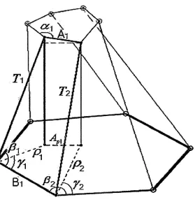
IS Common side conditions
Simply speaking, the sides o f polygon on the platform are used to be projected on
the base in order to develop the relation equations between inputs and variables. The
number o f the generic conditions can vary from 1 to 6 in terms o f the particular topology
we are discussing [figure 3.2],
33
To develop the corresponding equations, we take a particular polyhedron out o f the
system to research. In the highlighted tetrahedron, A I is the side we are using on the
platform. The side (B I) on the base, the lengths o f struts (TI and T2) and the moving side
(11) are known. The variables in this polyhedron are the projections o f struts (pi and p2)
and the angles between these struts’ projections and the base side (yl).
From top, one can develop:
lx - ( A 2 - P i - - P i )* = / „ (3.1)
From bottom, one can develop:
Combine and generalize:
=[pr
s™r, - pm
• s i "( P - r„
) T +[A
-p,
■c o sr, - p„ ■
^ ( P - r
M ) TLet us set generalize the above equations as:
= [P, ■ s in<t>n - p,+ ■ sin ]2 + [ B , ~ p t • cos</>n - p l+ ■ co s<f>,2]2
Where:
4
= /,.4 = z,
k
=r,
$2 = P m ~ Y m
/+ = / +1
This is the first set o f equations that obtained by common side conditions with two
types o f variables: length p and angle y. The number o f these equations could be up to 6
in terms o f the number o f vertices on the platform.
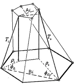
2S Common diagonal conditions
Similarly, when we take a look at a particular highlighted tetrahedron, which has a
side on platform acting as a diagonal [figure 3.3], w e are g o in g to use the 2S diagonal to
develop the kinematic equations.
35
35
(3.3)
(3.4)
(3.5)
(3.6)
(3.7)
(3.8)
(3.9)
*r
Figure 3.3: 2S Common Diagonal Condition
By the same way, the same set o f equations in terms o f common diagonal conditions
can be developed as (3.4), however, different Ai, Bi, O il, O i2 and i+ should be
substituted in for two types o f diagonals.
For those 2S diagonals, which are forming triangles with the corresponding 2
adjacent sides.
4 = V7/2 + lM ~ 2 ' 1‘' lM ■COS «/+!
B, = ^L , + Lm — 2 -Li - Lm • cos PM
<t>>x = Yi ~ arctan (l m • sin p M/ ( L , - LM ■ cos p M ))
(3.15)
(3.16)
h i = P m + P m ~ Y m + arctan ( Lm ■sin P m / ( Li ~ Lm ' cos fi M ) ) - n
z+ = / + 2
37
(3.18)
(3.19)
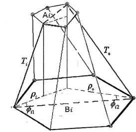
3S C om m on diagonal conditions
For those 3S diagonals, which are forming quadrangles with the corresponding 3
adjacent sides [figure 3.4].
A C *
Figure 3.4: 3S Common Diagonal Condition
A ~ [/; ■*" h+1 ^/+2 + 2 • • //+2 • cos(a/+1 + cc (+2) — 2 • /( • lMlj+2 • cos ccM • cos ccj+2 J (3.20)
5,. = [ l , 2 +LM2 + Li+2 + 2-L,- Li+2 • cos(/?/+1 + P i+2) ~ 2 • Lt ■ LMLl+2 ■ cos f i +1 ■ cos/3i+2J 2 (3.21)
37
/
arcsin (Z,.+1 - L , cos p M - I ,.+2 c o s # +2) P,+i+ x / 2 Vi Q 22)
arcsin (A+i ~L, cos/?+1 ~~Ij+2 cos/|+2)
I +& 2+/?+3 ft* 3n/ 2 (3.23) -Z, cos/?+1 -L i+2c o s /? +2)2 + ( 4 2 sin/?+2 -2 , sin$+l)
y
/+ — z + 3 (3.24)
Superposition conditions
We can image that in some cases two or more joints may superposed together. At
this time, another kind o f conditions should be taken into account: superposition
conditions because these are also the necessary conditions that determine the position and
orientation o f end-effector [Figure 3.5].
The condition equations’ development is illustrated by an example here. When the
first two joints on the moving platform are coincident with each other, we take the
39
B i
Figure 3.5: OS Superposition Condition
This condition is simpler comparing with the former two, we use the projection line
as common side the following equations can be developed:
T ? - p ? = T M* - p M* (3.25)
When n joints on the moving platform are superposed, n-1 equations can be
developed. Based on the above mentioned three conditions, up to 15 equations can be
derived in terms o f them and for those applicable topologies at least 12 equations can be
derived. The nonlinear kinematics model can be derived as following:
= [Pt ■ sin </>a - p i+ • sin <j>a f + [5, - p t • cos ^ - p M • cos </)a f (3.26)
rp2 2 rp 2 _ 2
1 i P i ~ J i+l P i+ \ (3.27)
39
To solve the above equations, as the motion is continuous, at each calculation step,
an initial estimate is the posture at the previous step. The convergence problem can be
solved mainly by choosing a very small time step, which require higher computing
capability and is not suitable for real-time applications. By using the extra sensors, we
can use the redundant data input from sensors to determine uniquely the solution o f the
forward kinematics and to provide a good initial estimate for the iterative solving process.
Another advantage o f the extra sensors is that they can be used for robot self-calibration
and also ensure the robot reliability in the case o f a sensor failure. The choice o f type and
disposition o f extra sensors is aimed at obtaining the unique solution to the forward
kinematics with a minimal number o f sensors. The sensors we are going to use are rotary
sensors for measuring the leg direction and it has been proved that at least four rotary
sensors are need for obtaining a unique solution, which means two o f joints on base
should be measured by four rotary sensors and each two sensors is assigned to get
direction o f the base universal joint on both axes so that the position o f corresponding
two joints on the moving platform are given, which are four adjacent variables for the
above equations.
3.1.2 Reconfigurable Inverse Kinematics
For inverse kinematics, the objective is to solve the six struts’ lengths with given