ISSN(Online): 2320-9801
ISSN (Print): 2320-9798
International Journal of Innovative Research in Computer
and Communication Engineering
(An ISO 3297: 2007 Certified Organization)
Vol. 3, Issue 8, August 2015
Bandwidth Enhancement by Slot Loaded
Proximity Coupled Equilateral Triangular
Microstrip Antenna for IMT/WIMAX/SAR
Applications
Mahesh C P
1, P M Hadalgi
2Research Student, Department of PG studies and Research in Applied Electronics, Gulbarga University, Kalaburagi,
Karnataka, India1
Professor, Department of PG studies and Research in Applied Electronics, Gulbarga University, Kalaburagi, Karnataka,
India2
ABSTRACT: This paper presents design and fabrication of inverted T-shape slot loaded on proximity coupled equilateral triangular microstrip antenna (ITSPCETMSA) for quad band operation is presented. The proposed antenna operates between 2.82 to 8.75GHz at four different frequency bands with enhancement in bandwidth to a maximum value of 52.52% to that of conventional microstrip antenna which resonates at 3GHz with bandwidth of 6.97%, by inserted inverted T-shape slot on the patch. The antenna parameters such as return loss, bandwidth and radiation pattern are discussed and presented. This antenna may find application in IMT, WIMAX and SAR (Synthetic aperture radar).
KEYWORDS: Equilateral triangular Microstrip antenna, proximity coupled, Inverted T-slot, bandwidth.
I. INTRODUCTION
In the present view first generation, second generation, third generation and recently, a fourth generation of mobile and wireless communication systems has already investigated. The growth of mobile and wireless communication systems has opened a wide range of opportunities to a new generation of antennas such as narrow single band, dual band, wide band and multi-band antennas. These necessities keep in mind, antenna designers to developed low profile antennas with a better bandwidth at each band [1]. The microstrip antennas are very popular due to their low profile, low-cost, ease of fabrication, bandwidth and radiation properties. Microstrip patch antenna consists of a radiating patch on one side of a dielectric substrate which has a ground plane on the other side. The patch is generally square, rectangular, circular and elliptical [2-3]. Therefore, the bandwidth enhancement is becoming a main kind design consideration for most practical applications of microstrip antennas for wireless communications. A plenty number of techniques have been established by the researchers to enhance the bandwidth of antennas. Many more techniques are used to enhance the bandwidth, most of these techniques some are summarized in [4-15].
However, these techniques are very difficult to design, so in this paper we concentrate on designing of a simple inverted T-slot loaded proximity coupled equilateral triangular microstrip antenna for enhancing bandwidth.
II. ANTENNA DESIGN CONSIDERATION
ISSN(Online): 2320-9801
ISSN (Print): 2320-9798
International Journal of Innovative Research in Computer
and Communication Engineering
(An ISO 3297: 2007 Certified Organization)
Vol. 3, Issue 8, August 2015
(1)
The proposed antennas are developed using software AutoCAD to achieve better accuracy and are fabricated on low cost glass epoxy substrate material of thickness h=0.32 cm with dielectric constant of Ɛr = 4.2 and tan ð = 0.02. The photolithography process is used to fabricate the antenna. The antenna is fed by using micostripline feeding. The microstripline feed of length Lf and width Wf is etched on the top surface of substrate S2. The substrate S2 is placed below substrate S1 such that the tip of the feedline and the center of the radiating patch coincide one over the other. The bottom surface of the substrate S2 acts as the ground plane. The h and Ɛr of substrates S1and S2 are same. The dimensions of the ground plane Lg and Wg are calculated from equation 2,
Wg = Lg = 6h+a (2)
Figure.1. Geometry of PCETMSA
The proximity coupled uses a two-layer substrate with the microstrip line on the lower layer and the patch antenna on the upper layer as shown in Fig. 1. The feed line terminates in an open end underneath the patch. This feed is better known as an electromagnetically coupled microstrip feed. The main advantage of this feeding technique is that it eliminates spurious feed radiation and provides very high bandwidth, due to overall increase in the thickness of the microstrip patch antenna. The major disadvantage of this feed technique is that it is difficult to fabricate because of the two dielectric layers which need proper alignment. Also, there is an increase in the overall thickness of the antenna.
Figure.2. Top view of ITSPCETMSA Figure.3. Geometry of ITSPCETMSA
ISSN(Online): 2320-9801
ISSN (Print): 2320-9798
International Journal of Innovative Research in Computer
and Communication Engineering
(An ISO 3297: 2007 Certified Organization)
Vol. 3, Issue 8, August 2015
inverted T-slot loaded proximity coupled equilateral triangular microstrip antenna (ITSPCETMSA) as shown in Fig. 2 and Fig. 3. All the specifications of designed antenna are given in Table. 1.
Table. 1 Designed specifications of the proposed antennas
Antenna Specifications Dimensions in cm
Side length of equilateral triangle (a) 2.70
Length of the feedline Lf 2.5
Width of the feedlineWf 0.633
Length and width of the ground plane
(Lg and Wg) 4.6
Thickness of substrate S1 and S2
(h1+h2) 0.64
x 0.65
y 0.7
z 1.5
III.RESULT AND DISCUSSION
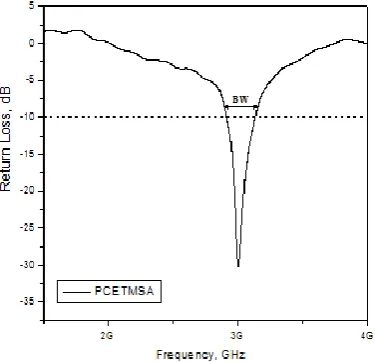
The impedance bandwidths over return loss less than -10 dB for the proposed antennas are measured. The measurements are taken on Vector Network Analyzer (Rohde & Schwarz, German make ZVK Model No. 1127.8651). The variation of return loss versus frequency of PCETMSA is as shown in Fig. 4. From the figure it is clear that, the antenna resonates at f1=2.82 GHz which is much closer to the designed frequency of 3 GHz and hence the validates the design. From this graph, the experimental impedance bandwidth is calculated using the formula (3),
𝐵𝑊 = 𝑓2−𝑓1
𝑓𝑐 × 100% (3)
where, f2 and f1 are the upper and lower cut off points of resonating frequency when its return loss reaches -10 dB and fc is a center frequency between f1 and f2.The PCETMSA resonates at 3 GHz with impedance bandwidth of 6.97% (2.91GHz - 3.12GHz).From the Fig. 5, it is found that the ITSPCETMSA resonates at quad bands offrequencies f1= 2.82 GHz (2.73GHz -2.93GHz), f2= 4.74 GHz (4.44GHz - 5.44GHz), f3= 7.17 GHz (6.99GHz -7.39GHz) and f4= 8.75 GHz (8.28GHz-10GHz), so the overall band width measured for ITSPCETMSA is 52.52%. The proposed antenna is compared with conventional microstrip antenna. All the results are reported in Table. 2.
ISSN(Online): 2320-9801
ISSN (Print): 2320-9798
International Journal of Innovative Research in Computer
and Communication Engineering
(An ISO 3297: 2007 Certified Organization)
Vol. 3, Issue 8, August 2015
Figure. 5. Variation of Return Loss v/s Frequency of ITSPCETMSA
Tabel. 2. Results of all the proposed antenna
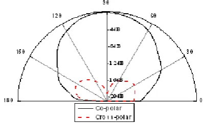
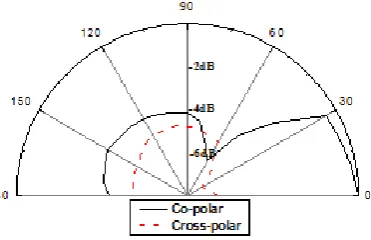
The X-Y plane co-polar and cross-polar radiation patterns of PCETMSA and ITSPCETMSA are measured at their resonating frequencies and are shown in Fig.6 to Fig.10. For the measurement of radiation pattern, the antenna under test (AUT) i.e., the proposed antennas and standard pyramidal horn antenna are kept in far field region. The AUT, which is receiving antenna, is kept in phase with respective transmitting pyramidal horn antenna. The power received by AUT is measured from -00 to +3600 with the step of 100. These figures indicate that the antennas show broad side radiation characteristics.
Figure. 6. Radiation pattern at 3 GHz
Antenna Resonant Frequency(G
Hz)
Return loss (dB)
Bandwidth in (%)age
Overall Bandwidth in
(%)age
PCETMSA 3 -30.26 6.97 6.97
ITSPCETMSA
2.82 4.74 7.17 8.75
-21.15 -15.49 -11.75 -24.89
7.06 21.09
5.56 18.81
ISSN(Online): 2320-9801
ISSN (Print): 2320-9798
International Journal of Innovative Research in Computer
and Communication Engineering
(An ISO 3297: 2007 Certified Organization)
Vol. 3, Issue 8, August 2015
Figure. 7. Radiation pattern at 2.82 GHz
Figure. 8. Radiation pattern at 4.74 GHz
Figure. 9. Radiation pattern at 7.17 GHz
ISSN(Online): 2320-9801
ISSN (Print): 2320-9798
International Journal of Innovative Research in Computer
and Communication Engineering
(An ISO 3297: 2007 Certified Organization)
Vol. 3, Issue 8, August 2015
IV.CONCLUSION
From the study, it is clear that the quad band operations of proposed antenna at four different bands of frequencies are possible by inserting a inverted T-slot on the patch with enhancement in bandwidth without affecting the primary band. The proposed antennas are very simple in their design and construction and they use low cost substrate material. These antennas may find application in IMT, WIMAX and SAR (Synthetic aperture radar).
REFERENCES
1. C. A. Balanis, “Antenna theory analysis and design”, John Wiley and Sons. Inc.
2. R. Garg, P. Bhartia, I. J. Bahl, A. Ittipiboon, "Microstripantenna design handbook", Artech House, Boston, Mass,USA, 2001 3. K.L. Wong, "Compact and broadband microstrip antennas", John Wiley & Sons, New York, NY, USA,
4. 2002
5. Zhong, S. S. and Y. T. Lo, “Single element rectangular microstripantenna for dual-frequency operation,” Elec. Letters, Vol. 19,No. 8, 298–
300, 1983.
6. Davidson, S. E., S. A. Long, and W. F. Richards, “Dualband microstrip antennas with monolithic reactive loading,” Elec.Letters, Vol. 21, No.
20, 936–937, 1985.
7. S. S. YAvalkar, R. T. Dahatonde, S. S. Rathod and S. B. Deosrkar, “Comparative analysis of bandwidth enhancement of microstrip patch antennas using various geometries”, IOSR Journal of Electronics and Communication Engineering (IOSR-JECE), Vol. 3, Issue. 4, (Sep-Oct. 2012), pp. 15-18.
8. Lin. S and Row. J, “Bandwidth enhancement for dual-frequency microstrip antenna with conical radiation”, Electronics Lett. 2008, 44(1),
pp-2-3.
9. P. K. Singhal and L. Shrivastava, “On the investigations of a wide band proximity fed bow tie shaped microstrip antenna”, Journal of Microwave and Optoelectronics, Vol. 3, pp. 87-98, April 2004.
10. RSA Raja Abdullah, D. Yoharaaj and Alyani Ismail, “Bandwidth enhancement technique in microstrip antenna for wireless applications”, PIERS Online, Vol. 2, No. 6, 2006, pp. 633-639.
11. Priyanka and Navin Srivastava, “Bandwidth enhancement for microstrip patch antenna using suspended techniques for wireless applications”,
International Journal of Advancements in Research and Technology, Vol. 2, Issue. 5, May-2013 pp. 231-235.
12. A. Abdelaziz, “Bandwidth enhancement of microstrip antenna”, Progress In Electromagnetics Research, PIER 63, 2006, pp. 311-317.
13. H. F. Abutarboush, H. S. Al-Raweshidy and R. Nilvalan, “Bandwidth enhancement for microstrip patch antenna using stacked patch and slot”,
IEEE 2009.
14. Amit Kumar, JaspreetKaur and Rajinder Singh, “Performance analysis of different feeding techniques”, International Journal of Emerging Technology and Advancsd Engineering”, Vol. 3, Issue 3, PP.884-890, March 2013.
15. D. M. Pozar and B. Kaufman, “Increasing the bandwidth of a microstripantenna by proximity coupling”, Electron.Lett., vol. 23, no. 8, pp.368–
369, Apr. 1987.