Software Development for Laser Marking
Machine
Janavi Shah1, Farah Pankhania 2, Prachi Panjwani 3, Anish Oswal 4, Asst. Prof. Vishal Meshram 5
U.G. Student, Department of Computer Engineering, Vishwakarma Institute of Information Technology, Kondhwa,
Pune, India1
U.G. Student, Department of Computer Engineering, Vishwakarma Institute of Information Technology, Kondhwa,
Pune, India2
U.G. Student, Department of Computer Engineering, Vishwakarma Institute of Information Technology, Kondhwa,
Pune, India3
U.G. Student, Department of Computer Engineering, Vishwakarma Institute of Information Technology, Kondhwa,
Pune, India4
Asst. Prof, Department of Computer Engineering, Vishwakarma Institute of Information Technology, Kondhwa,
Pune, India5
ABSTRACT: Laser marking provides a unique combination of speed, permanence and versatility. Laser engraving and marking is a manufacturing method for those application where previously Electrical Discharge Machining was the only choice. Laser engraving and marking removes material layer by layer and the thickness of layers is usually in range of few microns. Also, there are many types of laser machines available in recent times. Therefore, for optimum use of laser energy it is necessary to optimum use of process parameters to get best marking speed, quality. Laser marking machines are used for marking entities on the work piece.The software is developed for such machines. These machines are used for marking on different materials like metal, wood, etc. They use a laser source which emits laser on the material where marking is to be done. Previously, the marking procedure was manual where switches and buttons were to start the marking. The job on which marking is to be done had to be aligned manually before starting the mark. The quality of the mark was defined manually and if the marked entity had errors, it had to be defined by the operator. It is a tedious process to perform these tasks by hand. Therefore, software development is required for controlling the marking work, analysing and verifying the quality and introducing automation which would reduce the laborious work and bring efficiency in working hence saving a lot of time and manpower.
KEYWORDS: Laser engraving, Software Development, Electrical Discharge, Entities. I. INTRODUCTION
behind this project is to automate the marking process for Laser machines. This automation reduces the amount of labour required as well as saves time, which makes the system more efficient. These machines are used for marking on different materials like wood, metal, copper etc. They use a laser source, which emits a laser beam on the material where marking is to be done. Previously, manual methods like switches and buttons were used to start marking. The job had to be properly aligned, manually before starting the marking. The quality of the job also had to be checked manually. If the marked entity consisted errors, they had to be defined by the operators. Thus, these processes are very tedious to perform by hand. Software development for such machines proves to be efficient in controlling and analysing work. We develop a module where customers are given access to easy configuration of machine. It also does performance analysis and checks quality of the mark. The second module does real-time monitoring for errors and warnings in the machine and makes sure that the machine is working fine at all times. The third module is developed for automatic positioning of work piece and marking according to the calibrated data.
II. RELATEDWORK
2.1 Description: FOBBA MarksUS
It is both a convenient graphic design interface and a high-performance piece of software for the control ofthe laser marking system that produces the markings. The intuitive application is the control centre for all the marking related applications (2D) that are found in most of FOBAs systems. Marking contents are created quickly and efficiently. Premium-quality laser markings are applied precisely. As an option, the software can be equipped with the camera systems IMP and Point Shoot. Additionally, MarkUS contains the axis control and supports grayscales for the creation of impressive grayscale markings. MarkUS is compatible with many of FOBAs laser marking systems and laser marking machines, and is available in several languages. FOBAs MarkUS software reads and verifies codes: Serial barcodes, as well as 2D codes such as the QR and Datamatrix codes, are read within the marking field and compared to its expected content. The code reading option comes with a verification tool that provides means of passing or failing codes based on different factors such as the read content or the mark contrast. The Autofocus is used for easy and fast focusing process and a single click operation that works with almost any finished or coloured materials. It increases productivity, turns a 15 minutes’ job setup into a few seconds and reduces operator errors and scrap.
2.2 Description: MECCO
It provides standard software and custom graphical user interfaces for our SMARTmark Laser Marking Systems. JOB SETUP FEATURES Live ”Preview Mark” Capability: Avoid mistakes with easy job setup by being able to view an outline of the mark right on your part and make edits in real time without having to enter and exit a preview mode. Laser Marking Recipes: Our SMARTmark laser marking systems include laser marking profiles for easy setup using standard marking settings per material. Barcoding: MECCO’s software offers the ability to mark a wide range of 1D and 2D barcodes, and editing the codes overall size, cell size, line spacing, inversion and shape is made easy with our user interface. Includes the most commonly used options, such as: Laser Marking Fonts: Any TrueType font that is installed on the PC can be used within the laser marking software. These text objects can be utilized to create serial numbers, date and time codes, and shift or machine IDs, which can be marked in a straight line, radially, vertically, or even circumferentially. Filling capabilities: There is no longer any need to change fill settings in external software. Our software is capable of filling any TrueType font text or logo with ease, providing options for the fill pattern, angle of fill, fill spacing, and multiple passes for ultimate flexibility and mark control.
2.3 Description: SAMLight
It is based on the technology of SAM and provides the functionality for many industrial applications aswell as for job shops. The USB scanner controllers USC-1, USC-2 and USC-3 are SAM compatible hardware modules to drive a 2- or 3-axis laser scanner system. This software includes the following features
Job Editor
Pens and Styles
Barcode
Motion Control
III.EXISTINGSYSTEM
In the existing system the marking procedure was manual where switches and buttons were to start the marking. The job on which marking is to be done had to be aligned manually before starting the mark. The quality of the mark was defined manually and if the marked entity had errors, it had to be defined by the operator. It is a tedious process to perform these tasks by hand.
IV.PROPOSEDSYSTEM
The system is divided in three modules. The features are explained below:
A. Development of HMI
The user will be able to check if the marking machine is ON/OFF and if it is calibrated. The path to the Excelsheet should be specified to load the Excel sheet and obtain the data to pass it to the machine for marking. Different characteristic entities such as frequency, power, speed etc. need to be specified before starting the marking process. The user can also specify the number of jobs needed to be done and the starting job number. The marking process will be started accordingly referring to the job number in the excel sheet and it will be incremented automatically with the completion of each job. A CCD Camera will analyse the Quality status of each job. It will check for percentage similarity and burns; in case any are present. This status will be updated in the excel sheet along with the generation of a report. The report will contain the total number of jobs, number of completed jobs and the number of Not OK jobs. This report has to be emailed to theSupervisor. When the marking process starts the next time, it must first finish all the incomplete jobs.
B. Real Time Monitoring and Alert Eruption
The user of the system should be able to check that there are no errors present in the machine. It compares the generated value with the original value and if they are same the output is correct or else it is incorrect.
The user should be able to do the following functions:
Give instructions
Check the result.
The machine should be able to do the following functions:
Mark on the job
The software should be able to do the following functions:
Detect the error
Display actual and obtained values.
Generate alarm
Stop the machine
C. Camera Calibration and Processing
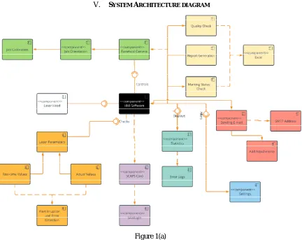
V. SYSTEM ARCHITECTURE DIAGRAM
Figure 1(a)
Figure 1(a) shows the System Architecture of all the components in the Software to be developed. It includes the representation of all the 3 modules. The green coloured boxes depict “Camera Calibration & Processing” module. The orange coloured boxes depict “Real-time error and Alert Eruption” module. The remaining boxes form a part of the “Human Machine Interface” module.
VI. CONCLUSION
The first part was development of HMI (Human Machine Interface) to control the machine. Herein user interface was developed where functionality is given to control the working of laser and result is obtained about the quality of the mark which will further be used for analysis to evaluate the performance of machine.
REFERENCES
[1] D. Belforte, "Overview of the laser machining industry," Technical Digest. Summaries of papers presented at the Conference on Lasers and Electro-Optics. Postconference Edition. CLEO '99. Conference on Lasers and Electro-Optics (IEEE Cat. No.99CH37013), Baltimore, MD, USA, 1999, pp. 82-.
[2] D. Castells-Rufas, O. Vila-Closas and J. Carrabina, "Design of a multi-soft-core based Laser Marking controller," 2012 International Conference on Reconfigurable Computing and FPGAs, Cancun, 2012, pp. 1-6.
[3] Z. Guoping, L. Pingwei, C. Shengyang and Z. Bo, "Design of Laser Marking Controller Based on ARM+FPGA," 2010 International Conference on Electrical and Control Engineering, Wuhan, 2010, pp. 752-754.
[4] Dongyun, Wang & Xinpiao, Ye. (2014). An embedded laser marking controller based on ARM and FPGA processors. TheScientificWorldJournal. 2014. 716046. 10.1155/2014/716046.
[5] G. Zhao, L. Lin, Y. Chen, S. Liu, J. Chu and Z. Luo, "Barcode character defect detection method based on Tesseract-OCR," 2017 3rd IEEE International Conference on Computer and Communications (ICCC), Chengdu, 2017, pp. 1767-1771.
[6] R. Smith, "An Overview of the Tesseract OCR Engine," Ninth International Conference on Document Analysis and Recognition (ICDAR 2007), Parana, 2007, pp. 629-633.
[7] Ayatullah Faruk Mollah , Nabamita Majumder , Subhadip Basu and Mita Nasipuri, “Design of an Optical Character Recognition System for Camerabased Handheld Devices”, IJCSI International Journal of Computer Science Issues, Vol. 8, Issue 4, No 1, July 2011.
[8] S. Gautam, A. K. Yadav and R. Gupta, "AC/DC/AC converter based on parallel AC/DC and cascaded multilevel DC/AC converter," 2012 Students Conference on Engineering and Systems, Allahabad, Uttar Pradesh, 2012, pp. 1-6.
[9] R. Nagarajan, Sazali Yaacob, Paulraj Pandian, M. Karthigayan, Shamsudin Hj Amin, Marzuki Khalid,"A real time marking inspection scheme for semiconductor industries”,"The International Journal of Advanced Manufacturing Technology, 2007", Volume 34, Number 9-10, Page 926 [10] M. Saez, F. P. Maturana, K. Barton and D. M. Tilbury, "Real-Time Manufacturing Machine and System Performance Monitoring Using
Internet of Things," in IEEE Transactions on Automation Science and Engineering, vol. 15, no. 4, pp. 1735-1748, Oct. 2018.
[11] S. G. Salve and K. C. Jondhale, "Shape matching and object recognition using shape contexts," 2010 3rd International Conference on Computer Science and Information Technology, Chengdu, 2010, pp. 471-474.