ABSTRACT
FENTON, MATTHEW ALLEN. Low-Cycle Fatigue Failure and Ratcheting Responses of Short and Long Radius Elbows at Room and High Temperatures. (Under the direction of Dr. Tasnim Hassan.)
In order to develop a comprehensive set of fatigue and ratcheting data of pipe elbows,
tests were performed on a set of NPS 2 (Nominal Pipe Size), stainless steel 304L,
schedule 10, 90° elbows. Such elbows are widely used in industries such as nuclear
power generation and chemical manufacturing. Under seismic events or
thermo-mechanical operations, elbow components can experience fatigue and ratcheting
damage. However, despite continued ASME Code design provision updates,
understanding of failures caused by ratcheting damage continues to be elusive,
therefore resulting in significantly conservative and costly designs. This thesis presents
displacement controlled testing results of both long and short radius elbows. In addition
to unpressurized tests, experiments were conducted at the 11.0 MPa (1600 psi) and 20.7
MPa (3000 psi) pressure levels. Force, displacement, change in diameters across the
flanks as well as the intrados and extrados data were collected. Moreover, axial and
circumferential strain gauges were placed at the elbow midsection at the extrados,
flank, and intrados. As high temperature conditions are frequently found in nuclear
power plants, a high temperature test at 350 °C was performed on a long radius elbow
specimen. In addition to the standard forms of strain gauge data acquisition, digital
image correlation was evaluated for strain measurement. The results compared the
effect of pressure on the responses, the effect of the elbow bend radius on the responses,
and the effect of high temperature. Finally, the results were compared with the design
© Copyright 2014 by Matthew Allen Fenton
Low-Cycle Fatigue Failure and Ratcheting Responses of Short and Long Radius Elbows at Room and High Temperatures
by
Matthew Allen Fenton
A thesis submitted to the Graduate Faculty of North Carolina State University
in partial fulfillment of the requirements for the degree of
Master of Science
Civil Engineering
Raleigh, North Carolina
2015
APPROVED BY:
______________________________________ ______________________________________
Dr. Christopher Bobko Dr. Mohammad Pour-Gauz
__________________________________________ Dr. Tasnim Hassan
ii DEDICATION
iii BIOGRAPHY
Matthew Fenton attended Purdue University in West Lafayette, Indiana for his
undergraduate study. After having developed an interest in both art and science, he
decided to major in civil engineering, with a focus in structural engineering. While at
Purdue, Matthew had the opportunity to perform undergraduate research at the Bowen
Laboratory, where he assisted on a joint American Institute of Steel Construction and
National Science Foundation project on the structural integrity of gravity frame steel
structures under Prof. Judy Liu. This experience, along with having already completed
concrete graduate design courses prompted him to enroll at North Carolina State
University for a Master of Science in Civil Engineering. Under the guidance of Dr.
Tasnim Hassan, Matthew conducted research experiments on the fatigue failure of
stainless steel elbows, as well as served as a teaching assistant for a couple semesters.
After graduation, Matthew plans to begin a career as a structural engineer and work
iv ACKNOWLEDGMENTS
I would like to thank my advisor, Dr. Tasnim Hassan for all his guidance throughout
the project. I appreciate his willingness to always answer questions as well as his
constant availability for helping with running tests. Another professor I would like to
thank Dr. Andrew Greishop for his ideas on concepting the cooling system. I would also
like to acknowledge Machel Morrison for his assistance in using the Material Test
System. Finally, I would like to thank Jake Rhoads for his help in constructing various
v TABLE OF CONTENTS
LIST OF TABLES ... viii
LIST OF FIGURES ... ix
Chapter 1 – Introduction ... 1
1.1 Background ... 1
1.1.1 Pipe Elbows... 2
1.2 Objectives ... 4
1.3 Motivation ... 4
1.4 Scope ... 5
1.5 Organization of Thesis... 5
Chapter 2 – Literature Review ... 6
2.1 Introduction ... 6
2.2 Room Temperature Tests ... 6
2.3 High Temperature Tests ...30
2.4 Summary of Previous Work ...41
Chapter 3 – Room Temperature Experimental Program ...44
3.1 Introduction ...44
3.1.1 Elbow Test Specimens ...44
3.1.2 Experimental Setup ...44
3.1.3 Data Acquisition ...46
vi
3.2 Short Radius Experimental Results...54
3.2.1 SR1 Results ...54
3.2.2 SR2 Results ...60
3.2.3 SR3 Results ...62
3.2.4 SR4 Results ...64
3.2.5 SR5 Results ...66
3.2.6 SR6 Results ...68
3.2.7 SR7 Results ...70
3.2.8 SR8 Results ...74
3.2.9 SR9 Results ...75
3.2.10 Fatigue Life Results ...75
3.3 Long Radius Experimental Results ...76
3.3.1 LR1 Results ...76
3.3.2 LR2 Results ...78
3.3.3 LR3 Results ...80
3.3.4 LR4 Results ...84
3.3.5 LR5 Results ...86
3.3.6 LR6 Results ...91
3.3.7 LR7 Results ...91
3.3.8 Fatigue Life Results ...92
3.4 Discussion on Short and Long Radius Elbow Results ...93
vii
3.4.2 Bend Radius Influence Discussion ... 103
Chapter 4 – High Temperature Experimental Program ... 111
4.1 Introduction ... 111
4.1.1 Experimental Setup ... 111
4.1.2 Data Acquisition ... 114
4.2 High Temperature Experimental Results... 115
4.2.1 HTLR1 Results ... 116
4.3 Comparison between Room and High Temperature Results ... 121
Chapter 5 – Evaluation of the ASME Code... 124
5.1 Introduction ... 124
5.2 ASME BPVC Section III ... 124
5.2.1 Elbow Experimental Results and Code Comparison ... 127
5.3 Bree Diagram ... 128
Chapter 6 – Conclusion ... 131
6.1 Experimental Results ... 131
6.2 Code Analysis Results ... 133
6.3 Future Work ... 133
REFERENCES ... 135
viii LIST OF TABLES
Table 3.1: Loading parameters for both short and long radius (SR and LR) elbows. ...54
Table 3.2: SR1 elbow thickness and diameter measurements. ...58
Table 3.3: Fatigue lives from the short radius elbow tests. ...76
Table 3.4: Fatigue lives from the long radius elbow tests. ...92
Table 3.5: Summary of fatigue lives of elbow tests. ...94
ix LIST OF FIGURES
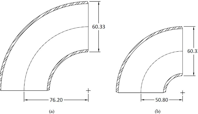
Figure 1.1: Detail of NPS 2 long radius elbow, (a) and short radius elbow, (b) showing
the bend radii of each as well as the actual diameter. ... 3
Figure 2.1: Diagram of Markl's testing frame (Markl, 1952). ... 7
Figure 2.2: Test setup for the elbow specimens (Suzuki & Nasu, 1989)...10
Figure 2.3: In-plane elbow test setup (General Electric Nuclear Energy, 1994). ...13
Figure 2.4: Test specimen and loading frame diagram (Sakai et al., 1995). ...16
Figure 2.5: Test specimens within loading frame (Yahiaoui et al., 1996). ...18
Figure 2.6: Elbow test specimen and setup (Suzuki et al., 2002). ...20
Figure 2.7: Model test specimen and setup (Suzuki et al., 2002). ...21
Figure 2.8: Line diagram of elbow testing setup (Chen et al., 2006). ...23
Figure 2.9: Overview of the test setup (Karamanos et al., 2006). ...25
Figure 2.10: Image of the elbow test setup (Varelis et al., 2013). ...27
Figure 2.11: Image of a pressurized elbow test setup (Varelis & Karamanos, 2014)...29
Figure 2.12: Diagram of the testing frame (Heald & Kiss, 1974). ...32
Figure 2.13: Schematic of the loading frame and test specimen (Imazu et al., 1977). ...35
Figure 2.14: Test frame within a safety tank (Bhandari et al., 1986). ...37
Figure 2.15: Drawing of the elbow test setup (Hilsenkopf et al., 1988). ...38
Figure 2.16: Diagram of test specimen (Ueda et al., 1990). ...40
x Figure 3.2: Diagram of the pressurization system. ...46 Figure 3.3: (a) shows an image of the ΔD Device while mounted on a test specimen and (b) shows a line detail of the ΔD Device and identifies the individual components. ...48
Figure 3.4: Elbow thickness measurement locations along various (a) planes around (b) cross-sections. ...49
Figure 3.5: (a) DIC camera pointed at the speckle pattern on a test specimen and (b) speckle pattern appearing on screen. ...52
Figure 3.6: SR1 fatigue failure through-wall crack. ...55 Figure 3.7: SR1 responses (a) force-displacement (P-δ) hysteresis loops and (b) peak and valley force responses as a function of cycle number. ...55
Figure 3.8: SR1 change in diameter (ΔD) responses across the (a) flanks (ΔDx) versus displacement and (b) ΔDx versus cycle number and across the (c) intrados-extrados (ΔDy)
versus displacement and (d) ΔDy versus cycle number. ...56
Figure 3.9: SR1 strain responses versus displacement for the (a) flank circumferential strain, (b) flank axial strain, (c) extrados circumferential strain, (d) extrados axial
strain, (e) intrados circumferential strain, and (f) intrados axial strain...57
Figure 3.10: Problem with obtaining intrados thickness measurements for short radius elbows. ...59
Figure 3.11: Abridged SR2 results with (a) load versus displacement, (b) load versus cycle, (c) change in diameter at the flanks versus displacement, (d) change in diameter
at the flanks versus cycle, (e) circumferential strain at the flank versus displacement,
xi Figure 3.12: SR3 plot showing non-steady pressure. ...62 Figure 3.13: Abridged SR3 results with (a) load versus displacement, (b) load versus cycle, (c) change in diameter at the flanks versus displacement, (d) change in diameter
at the flanks versus cycle, (e) circumferential strain at the flank versus displacement,
and (f) axial strain at the flank versus displacement. ...63
Figure 3.14: Abridged SR4 results with (a) load versus displacement, (b) load versus cycle, (c) change in diameter at the flanks versus displacement, (d) change in diameter
at the flanks versus cycle, (e) circumferential strain at the flank versus displacement,
and (f) circumferential strain at the other flank versus displacement. ...65
Figure 3.15: Abridged SR5 results with (a) load versus displacement, (b) load versus cycle, (c) change in diameter at the flanks versus displacement, (d) change in diameter
at the flanks versus cycle, (e) circumferential strain at the flank versus displacement,
and (f) axial strain at the flank versus displacement. ...67
Figure 3.16: SR6 abridged results with (a) load versus displacement, (b) load versus cycle, (c) change in diameter at the flanks versus displacement, (d) change in diameter
at the flanks versus cycle, (e) circumferential strain at the flank versus displacement,
and (f) circumferential strain at the other flank versus displacement. ...69
xii at the flanks versus cycle, (e) circumferential strain at the flank versus displacement,
and (f) circumferential strain at the other flank versus displacement. ...73
Figure 3.20: SR8 load versus displacement response. ...74 Figure 3.21: SR9 load versus displacement response. ...75 Figure 3.22: LR1 abridged results with (a) load versus displacement, (b) load versus cycle, (c) change in diameter at the flanks versus displacement, (d) change in diameter
at the flanks versus cycle, (e) circumferential strain at the flank versus displacement,
and (f) circumferential strain at the other flank versus displacement (Hassan et al.,
2015). ...77
Figure 3.23: LR2 abridged results with (a) load versus displacement, (b) load versus cycle, (c) change in diameter at the flanks versus displacement, (d) change in diameter
at the flanks versus cycle, (e) circumferential strain at the flank versus displacement,
and (f) circumferential strain at the other flank versus displacement (Hassan et al.,
2015). ...79
Figure 3.24: LR3 abridged results with (a) load versus displacement, (b) load versus cycle, (c) change in diameter at the flanks versus displacement, (d) change in diameter
at the flanks versus cycle, (e) circumferential strain at the flank versus displacement,
and (f) circumferential strain at the other flank versus displacement. ...81
Figure 3.25: LR3re abridged results with (a) load versus displacement, (b) load versus cycle, (c) change in diameter at the flanks versus displacement, (d) change in diameter
at the flanks versus cycle, (e) circumferential strain at the flank versus displacement,
xiii Figure 3.26: LR4 abridged results with (a) load versus displacement, (b) load versus cycle, (c) change in diameter at the flanks versus displacement, (d) change in diameter
at the flanks versus cycle, (e) circumferential strain at the flank versus displacement,
and (f) circumferential strain at the other flank versus displacement (Hassan et al.,
2015). ...85
Figure 3.27: LR5 abridged results with (a) load versus displacement, (b) load versus cycle, (c) circumferential strain at the flank versus displacement, and (d) axial strain at the flank versus displacement. ...87
Figure 3.28: DIC tensile peak circumferential strain contour plots (in percent) at the flank for the specified cycles. ...88
Figure 3.29: Cycle 11 tensile peak circumferential strain contour plot with specific points selected. ...89
Figure 3.30: Cycle 11 tensile peak circumferential strain variations along (a) u1-u8 and (b) v1-v5...90
Figure 3.31: DIC and strain gauge comparison for peak tensile circumferential strain values. ...90
Figure 3.32: LR6 load versus displacement response. ...91
Figure 3.33: LR7 load versus displacement response. ...92
Figure 3.34: Influence of pressure on fatigue life. ...95
Figure 3.35: Short radius force responses (a) mean (Pm) and (b) amplitude (Pc). ...96
xiv Figure 3.37: Short radius circumferential strain responses (a) mean (εmθ) and (b)
amplitude (εaθ). ...98
Figure 3.38: Long radius force responses (a) mean and (b) amplitude. ... 100
Figure 3.39: Long radius change in diameter responses (a) mean and (b) amplitude. 101 Figure 3.40: Long radius circumferential strain responses (a) mean and (b) amplitude. ... 102
Figure 3.41: Load amplitude response comparison between (a) short and (b) long radius elbows. ... 104
Figure 3.42: Load mean response comparison between (a) short and (b) long radius elbows. ... 105
Figure 3.43: Change in diameter amplitude response comparison between (a) short and (b) long radius elbows. ... 106
Figure 3.44: Change in diameter mean response comparison between (a) short and (b) long radius elbows. ... 107
Figure 3.45: Circumferential strain amplitdue response comparison between (a) short and (b) long radius elbows. ... 108
Figure 3.46: Circumferential mean strain response comparison between (a) short and (b) long radius elbows. ... 109
Figure 4.1: Furnace setup around a test specimen. ... 112
Figure 4.2: Diagram of cooling system. ... 113
Figure 4.3: Image of test specimen cooling system. ... 114
xv Figure 4.5: Determining the fatigue life of HTLR1 through (a) load versus time and (b) load amplitude versus cycle. ... 118
Figure 4.6: HTLR1 responses of (a) load verus displacement and (b) load versus cycle. ... 119
Figure 4.7: HTLR1 cycle 675 DIC circumferential strain. ... 120 Figure 4.8: Long radius elbow comparison between room and high temperature load (a) mean and (b) amplitude. ... 123
1
Chapter 1 – Introduction
1.1
Background
Piping and its various components make up critical internal systems within industrial
structures such as nuclear power plants and chemical installations. They are used to
transport fluids ranging from room to high temperatures. One particular component
used frequently is the 90° elbow due to the flexibility it grants when designing pipe
systems.
Historically, the 90° elbow has been difficult to properly analyze and model. This arises
due to its complex geometry. While being deformed, the cross-section of the elbow
undergoes ovalization. This ovalization can either stiffen or weaken the elbow
depending on the kind of deformation such as opening or closing, as well as causes high
strain concentrations which increase the probability of failure. The result has led to
overcompensation in the design codes and wasteful overdesigning by engineers (Han, et
al., 2012).
Even with such precautions, piping still experience critical failures at both service levels
due to fatigue and thermal gradients. In a review of fatigue failures in Japanese Light
Water Reactor (LWR) nuclear power plants, service level failures have been observed,
some of which resulted in temporary plant shutdowns (Iida, 1992). The actual reactor
2 systems, pumps, and valves were the areas that saw failure. Two causes were
ascertained: mechanical-vibration-induced fatigue and thermal-fluctuation-induced
fatigue, with vibration-induced fatigue occurring more often than previously believed
(Iida, 1992). One mechanical-vibration-induced fatigue observed occurred in the splitter
plate of stainless steel of type 316 elbows that were part of the primary coolant system
of a power plant. One thermal-fluctuation-induced fatigue recorded involved a crack at
the butt welded joint between an elbow and a straight pipe which resulted in leakage of
the internal fluid. In the end, even though there was no critical damage to the reactor
structure, a shutdown and expensive repairs were still required (Iida, 1992).
An investigation into seismic damages to industrial facilities from earthquakes ranging
from 1960 to 2000 found that while design codes called for damage caused to the piping
systems of general and high pressure gas manufacturing facilities to be limited to
deformations, many installations had piping systems that had either leakage or
complete fluid stoppage within the pipes. Such failures have triggered new provisions
within the design codes as well as research into more advanced damping systems
(Suzuki K. , 2008).
1.1.1
Pipe Elbows
The pipe elbow consists of two standard types, the long radius elbow and the short
radius elbow. The two types are differentiated by the bend radius, as their names imply.
The long radius elbow has a bend radius of 1.5 times the nominal diameter while the
3 both a long radius and short radius NPS 2 (Nominal Pipe Size) elbow with a 60.33 mm
outer diameter. The NPS dimensions are a North American standard set of pipe sizes
and were defined by ANSI (American National Standards Institute).
(a) (b)
Figure 1.1: Detail of NPS 2 long radius elbow, (a) and short radius elbow, (b) showing the bend radii of each as well as the actual diameter.
The elbow thicknesses are defined in the ANSI B36.10M for carbon steel and in the
B36.19M for stainless steel. Elbow thicknesses are referred to as schedules, which are
numbers derived from a certain ratio of the service pressure to the allowable stress. For
carbon steel, schedules range from schedule 10 to 160, with many values falling into
categories of thin wall, standard weight, and extra strong. In the case of stainless steel,
4 Steel pipe elbows are not threaded, and are all welded to straight pipe sections to
comprise pipe systems.
1.2
Objectives
The main objective of this project is to examine the behavior of NPS 2, 304L stainless
steel elbows under in-plane bending and cyclic loading both at room and high
temperatures. Both short and long radius elbows are considered and compared with
each other. In order to accomplish this objective, the following tasks were completed:
a. Room temperature tests were performed on elbows using a uniaxial hydraulic
load system from MTS Systems Corporation.
b. Pressurized room temperature tests were performed on the MTS load system.
c. High temperature testing was conducted on the MTS load system. This included
a design and implementation of a heat sink and water cooling system.
1.3
Motivation
As shown in the following chapter, the mechanisms behind low cycle fatigue failures are
still not well understood. Many investigators are still performing experiments on elbow
specimens in order to derive a comprehensive set of data in order to explain and to be
able to predict behavior of elbows experiencing low-cycle fatigue loading. In addition,
many such experiments are focused on long radius elbows and in almost all cases,
exclusively. This purview is not entirely without just cause, as in fact long radius elbows
5 are only used when spatial constraints become a concern (Parisher & Rhea, 2002).
However, simply because long radius elbows are the default choice does not mean that
short radius elbows are not used at all. For example, certain designs of nuclear power
reactors can have limitations in their size, and therefore short radius elbows are more
versatile in such a setting (Sakai, Yamamoto, & Hagiwara, 1995). Therefore,
understanding the behavior of short radius elbows is important, and especially in
determining if and when their behavior substantially differs from long radius elbows.
1.4
Scope
The scope of this project covers the preparation and testing of the elbow specimens. The
parameters tested include elbow bend radius, displacement amplitude, internal
pressure, and high temperatures. Previous experimental long radius elbow results
presented by Hassan et al. (2015) are also compared with in this project.
1.5
Organization of Thesis
This thesis is organized into chapters. Chapter one consists of the introduction
including background information and the project objectives. Chapter two contains the
literature review. Chapter three discusses the room temperature tests while chapter
four presents the high temperature tests. Finally, chapter five analyzes the results with
respect to the ASME code and chapter six summarizes the results and conclusions as
6
Chapter 2 – Literature Review
2.1
Introduction
As the function of the piping systems of industrial structures are critical to their
operation, especially with regard to nuclear or chemical plants, research has been
undertaken to understand the behavior of the components that comprise such systems.
Numerous tests have been performed on the 90° elbow component in order to determine
its behavior. However, many of these tests were done at room temperatures. As the real
world application of these components are at high temperatures, ranging from 200 °C to
350 °C for nuclear facilities and at an even greater variability for chemical installations,
high temperature testing is more important. There have been some high temperature
experiments, but due to the difficulty in performing them the quantity available has not
been very comprehensive.
2.2
Room Temperature Tests
One of the earliest fatigue tests was performed by Markl (1952). Seeing the need for
information on the behavior of piping systems subjected to cyclic bending loads from
thermal expansion or contraction, pressure pulses, and vibrations in order to provide
design data for piping engineers, the Product Engineering and Research Department of
Tube Turns, Inc. initiated a full scale fatigue testing program, conducted by Markl. The
testing program included a variety of piping components including straight pipe,
7 bends, and more relevantly, elbows. A testing frame was devised such that it could test
both straight pipe specimens and L-shaped specimens in both in-plane and out-of-plane
cyclic bending. One end held specimens rigidly while the other consisted of a hinged end
connected to an actuator. Figure 2.1 shows a line diagram of the testing setup.
Figure 2.1: Diagram of Markl's testing frame (Markl, 1952).
After the tests were performed, S-N (stress versus cycle) diagrams were compiled and
analyzed, as specimens were loaded such that the endurance limit, where a stress
amplitude could be sustained in perpetuity, could be determined for each type of piping
component. However, in the conclusion the author notes that the stresses were
estimates, as they were based on many assumptions. Therefore, a design procedure with
conservative piping stress calculations was proposed for fatigue life determinations
8 Edmunds and Beer (1961) published a paper on fatigue failure due to ratcheting. The
authors investigated the factor concerning the possibility of taking advantage of strains
greater than yield in high strain fatigue endurance of materials when designing for a
certain life span. Specifically, ratchet failure, or incremental collapse as referred to by
the investigators prevents designers from making use of the endurance of the material
in pressure vessels. While a significant portion of the paper is dedicated to analysis of
both incremental shakedown and incremental collapse, other portions included tests on
piping components that had not been done previously. A relevant test was on short
radius pipe bends. Unlike pipe elbows, pipe bends include the straight pipe sections and
the 90° curve all as one piece. The pipe bends were tested at varying levels of internal
pressure, and with each increase in pressure there was also a corresponding increase in
in-plane bending deflections up to four cycles. Using stress analysis, incremental
collapse limits were calculated. In the conclusion, the authors recommend additional
tests to investigate the assumptions made with the analysis performed (Edmunds &
Beer, 1961).
A large scale room temperature experiment on elbow connections with monotonic
loading was performed by Greenstreet (1978). The investigation was concerned with the
plastic collapse failure mode of elbows, and therefore an experiment into determining
allowable loads was performed. Twenty commercial short and long radius elbows with a
152.4 mm nominal diameter were loaded by external forces and by a combination of
9 carbon steel and ASTM A-312 type 304L stainless steel and the elbow thicknesses were
either schedule 40 or schedule 80. Dial indicators were used to determine limit loads for
the elbows while strain gages were used for verification purposes and to provide details
on the plastic collapse. The final elbow test specimen was comprised of an elbow butt
welded to 457.2 mm pipes at both ends. One pipe end was fixed and the other end was
connected by a roller support to a hydraulic ram, which applied the loading. Loading
was slowly applied through increasing stepwise increments in either in-plane opening,
closing, or out-of-plane loading. In the cases where internal pressure was applied, a
10.34 MPa pressure was used. Load-deflection curves were obtained for all specimens.
The results showed that for a given elbow with a certain wall thickness, bend radius,
and material under external alone, an in-plane closing type loading will have a smaller
collapse moment than the other two types of loading. In the presence of internal
pressure, the collapse moment is generally increased in all loading cases. While the
primary purpose of the experiments was to determine in-plane and out-of-plane limit
loads, the experiments did yield other secondary results. Carbon steel has a higher
collapse load while the transition from linear behavior to plastic behavior for stainless
steel occurs more quickly. The presence of internal pressure provides a higher collapse
load while quickening the movement from linear response to plastic response for both
steel types. Finally, the ovalization in the elbow geometry remained generally small.
Stainless steel exhibited the greatest ovaling, ranging from 9 to 15% after testing was
10 Suzuki and Nasu (1989) conducted an experiment on larger diameter butt-welded
elbows, specifically on one 304.8 mm and one 609.6 mm outer diameter long radius 90°
elbows by subjecting them to in-plane monotonic bending. The objective of the
experiment was an early attempt to verify a four-node shell element of the program
ADINA in order to develop an alternative to full scale testing of elbows in order to
determine their behavior and flexibility under earthquake induced ground motions.
Therefore data on load-displacement, strain distributions, and the change of elbow
diameters were collected. The bending tests consisted of setting an elbow test specimen,
which was an elbow welded to two pipes, in a pinned end support configuration which is
shown in Figure 2.2.
Figure 2.2: Test setup for the elbow specimens (Suzuki & Nasu, 1989).
Loading was applied through a hydraulic actuator attached as a hinge at one of the pin
11 displacement of 130 mm for the 304.8 mm elbow and 240 mm for the 609.6 mm elbow.
The model simulation ultimately showed excellent concurrence with collected data
within the linear elastic range, but the model diverges at the onset of the plastic
response. Maximum strains up to 2% were predicted well. However, the testing and
modeling was only done under monotonic loading, and thus neglects the reverse loading
found in earthquakes. (Suzuki & Nasu, 1989).
In the early 1990s a massive undertaking by the Electric Power Research Institute
(EPRI) and the Nuclear Regulatory Commission (NRC) was performed due to a
prevailing industry concern that the current piping design code was extremely
conservative in seismic and other reverse dynamic loadings in nuclear power piping.
Called the Piping and Fitting Dynamic Reliability Program, the overall project goal was
to determine potential changes to the current code in order to improve piping system
safety and reliability. The investigation was comprised of 41 different piping
components, 24 of which were 152.4 mm nominal pipe size (NPS) elbows. Of the 24, 21
elbows were tested under in-plane bending. Two elbows were tested under high
frequency dynamic loading (water hammer conditions), one elbow was tested under mid
frequency dynamic loading (hydrodynamic input), two more elbows were tested under
static collapse (monotonic opening and closing), but more relevantly the remaining 16
elbows were tested under seismic loading (safe-shutdown earthquake or sine sweep
loading). Both carbon steel and stainless steel elbows were included. The elbow
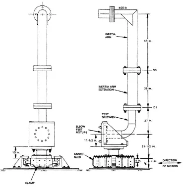
12 strong, respectively). The elbows were also subjected to various pressure levels, with
two remaining unpressurized. All but one elbow were long radius, with that particular
elbow being a short radius type. The elbow test specimens consisted of an elbow welded
to two pieces of straight pipe. A flanged end block was welded to the end of one pipe,
which could then be bolted onto the test fixture. The other pipe end was welded to a
flange so that an inertia arm could be bolted. The inertia arm consisted of two pieces of
203.2 mm schedule 80 pipe which was welded together in an L-shape. Weights could
then be added at the top of the inertia arm to control the natural frequency of the test
system and to apply inertial load to the test specimen. A line diagram details the test
13
Figure 2.3: In-plane elbow test setup (General Electric Nuclear Energy, 1994).
The test fixture itself was mounted on a shake table, where four 11,000 lb hydraulic
actuators could apply dynamic loading. The seismic loading consisted of 7.0 – 7.5 Hz
over 20.48 seconds for the schedule 80 elbows, and 6.3 Hz over 22.76 seconds for most of
the schedule 40 elbows, with a 1.3 Hz over 110.3 seconds for the remaining components.
The failure mode generally observed was fatigue ratcheting. Two tests did not show
14 to the prevailing understanding at the time, which was that earthquake loading caused
plastic collapse in piping systems (General Electric Nuclear Energy, 1994).
Boussaa et al. (1994) examined three of the dynamic tests performed by EPRI and
performed a fatigue life analysis using first a global approach as detailed by Markl and
a local approach based on local fatigue failure criteria with a proposal from Coffin to
account for ratcheting. Predicting fatigue life under general loading paths was an open
problem, and the additional variables of multiaxiality and amplitude variability with
ratcheting was unexplored at the current time. The investigators attempted to perform
an analysis now that experimental data was available. The three elbow tests selected
from the EPRI experimental program were all 152.4 mm nominal diameter schedule 40
long radius elbows. One elbow was of carbon steel, and the other two were made of
stainless steel. Each elbow was pressurized to 11.7 MPa, 11.7 MPa, and 6.9 MPa,
respectively. An inertia loading sequence was applied on each elbow by a shake table
which lasted 22.7 seconds each. Subsequent sequences were performed until failure of
the elbow, which was the formation of a through-wall crack at either flank was
observed. The results of the global analysis showed some reasonableness in fatigue life
predictions. Although Markl’s equation was developed through tests on 101.6 mm
unpressurized carbon steel specimens, the comparison of the analytical results agreed
well with the pressurized carbon steel experimental results, but had varying results
with the stainless steel elbows. The results of the local approach, however, show a poor
15 due to the sensitivity of fatigue laws, the uncertainty of material properties has a large
influence on the results. The report concludes that in terms of additional investigation,
the global approach requires a look at the effects of internal pressure and the
differences between the fatigue parameters of carbon and stainless steel. The local
approach requires more data on fatigue-ratcheting interactions as well as a better way
to determine best-fit parameters for short lives (Boussaa et al., 1994).
Sakai et al. (1995) carried out an experiment specifically on a short radius elbow. The
investigators were concerned with the seismic response of short radius elbows due to
their exclusive use in a Demonstration Fast Breeder Reactor (DFBD) as a result of
spatial constraints. As Sakai et al. (1995) were unable to find much dynamic strength
test data, an experiment and static FEM analysis was conducted. The single test
specimen consisted of a short radius stainless steel SUS304 10B schedule 5S 90° elbow
welded to two straight pipes of equivalent material and diameter. The outer diameter of
the model elbow measured 267.4 mm. The test setup consisted of placing the elbow test
specimen in a pinned support configuration, with one end connected to a load cell and
the other end connected to a weight. The entire setup was placed upon a shake table,
16
Figure 2.4: Test specimen and loading frame diagram (Sakai et al., 1995).
The result of the seismic loading was a through-wall crack failure at both flanks of the
elbow within 82 seconds from the start of excitation. The investigators noted that this
result conflicted with the current understanding at the time, which was that the
traditional failure mode of piping systems under earthquake loading was plastic
collapse. The static FEM analysis investigated a case where the elbow is initially closed,
then opened, and then closed again and another case were was elbow was initially
opened, then closed, and then finally opened. The results showed that the hoop strain
distribution was localized at both flanks, which matched the crack locations. However,
the model underpredicted the maximum load when the model was displaced in the
closing direction, which the authors thought could be caused by a difference of thickness
in the elbow or an effect of material hardening during the manufacturing process of the
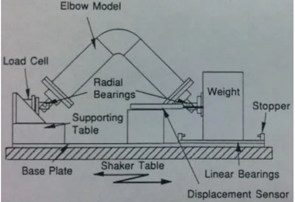
17 An experiment performed by Yahiaoui et al. (1996) focused on the seismic response of
pressurized pipe elbows under in-plane bending. The experiment consisted of eight pairs
of 50.8 mm nominal diameter elbows of both carbon and stainless steel and long and
short radii. Straight pipe of four times the outer elbow diameter in length was welded to
one end of an elbow and pipe of twelve times the outer elbow diameter was welded to
the other end. Each elbow pair was tested simultaneously within a symmetric setup and
pressurized by hand pumped oil to their design pressure. The elbows were placed into
vertical frame capable of applying displacement loading through a hydraulic ram on the
top crosshead to the short pipe ends. Constant force springs were attached to
deadweights located on the free long pipe ends of both specimens. Figure 2.5 gives an
18
Figure 2.5: Test specimens within loading frame (Yahiaoui et al., 1996).
Each test was performed by subjecting the elbows to a simulated seismic event over a
period of 5 to 20 seconds and then consecutively increasing the input level for
subsequent events until the components reached failure. Due to limitations of the
testing frame, the maximum applied displacements were limited to ±10 mm. The results
showed that the dynamic responses of carbon steel elbows differed dramatically from
the stainless steel elbows. The carbon steel elbows exhibited an elastic-perfectly plastic
behavior while the stainless steel elbows showed a strain-hardening type of behavior.
Cyclic strain accumulation was observed to be greatest in the flank hoop direction
rather than the axial direction. For the short radius elbows, ratcheting was significant
19 moment were observed, indicating that plastic collapse may not have been the ultimate
governing failure mode. Finally, permanent deformation such as ovalization was not
recorded in any of the tests (Yahiaoui et al., 1996).
A report by Tan et al. (2002) compiled significant experimental research along with
finite element analysis (FEA) of in-plane nonlinear monotonic bending of elbow and pipe
components. The purpose was to determine if FEA models could adequately simulate
the nonlinear behavior of straight pipes and elbows well enough for design purposes. A
summary of percent error between experimental results and model calculations ranged
from 6 – 15% across the six studies reviewed. The report concludes with updated FEA
for both straight pipe and elbows based on a modeling study of 50.8 mm schedule 40
stainless steel elbows and aluminum straight pipe which achieves more accurate results
(Tan et al., 2002).
In the fiscal year of 1998, the Nuclear Power Engineering Corporation (NUPEC) in
Japan decided to initiate a research program investigating the elasto-plastic response
and ultimate strength of the nuclear piping system, the seismic safety margins of the
current design code for piping, and new allowable stress rules. This program came about
due to the remaining technical issues related to the understanding of piping behavior
with plasticity, as seen in research done on the failure modes of ratcheting and collapse.
Suzuki et al. (2002) have reported on a piping component test performed under the
20 included elbow specimens. The specimens consisted of 216.3 mm diameter schedule 40
elbows welded to two pipe extensions. The material included SUS304TP and STS410(A)
stainless steels. The specimen pipe ends were attached to two pin connections, with one
pin connection connected to a mass on a shake table as shown in Figure 2.6.
Figure 2.6: Elbow test specimen and setup (Suzuki et al., 2002).
Two loading types were performed: a quasi-static loading and a dynamic shaking. The
quasi-static consisted of a deflection controlled sine wave while the dynamic shaking
was an input acceleration control of a seismic wave. The results of the quasi-static cyclic
loading showed that the load-deflection curves of all elbow specimens shifted upwards
with increasing cycles. The hoop strain ratcheted the greatest at the mid flank location,
which was also the location of the through-wall crack failure. In the dynamic shaking
tests, the load-deflection curves shifted to the left with increasing cycles, showing a
permanent increase of deformation in the opening direction. Hoop strains show
ratcheting near the crack, but the axial strains do not. The report also included a test on
a simplified piping model. The model that tested elbow specimens consisted of a center
21 was then welded to the other ends of the elbows. The model itself was tested with a
shake table under dynamic loading which is shown in Figure 2.7.
Figure 2.7: Model test specimen and setup (Suzuki et al., 2002).
The failure mode of the elbows in the simplified piping system were still fatigue cracks
rather than plastic collapse and buckling. However, axial cracks instead of hoop cracks
22 While not specifically on elbow components, an experiment performed by Miyazaki et al.
(2002) focused on cyclic loading of the carbon steel pipes that the nuclear industry uses
which are critical to the overall pipe system. The 114.3 mm outer diameter schedule 80
pipes were subjected to local wall thinning in order to simulate corrosion. Two pipes
underwent a load controlled test while four pipes were tested under displacement
control. In the results of the load controlled tests, ductility damage from ratcheting
deformation decreases the fatigue strength of the pipe. For the results of the
displacement controlled test, fracture behavior was not accompanied by ratcheting
deformation, allowing the fatigue strength to be determined by the current fatigue
design curve (Miyazaki et al., 2002).
Chen et al. (2006) conducted an experiment to study the phenomenon of ratcheting in
low carbon steel elbows under reversed bending. The test specimen was composed of a
76 mm low carbon steel #20 (Chinese code GB12459-90) long radius elbow welded to two
pipes of 100 mm in length. The pipe ends were welded to a connecting block which
allowed for a pin connection to the loading bar of the test machine. The test machine,
which is shown in Figure 2.8, consisted of a load cell at one end of the specimen and a
23
Figure 2.8: Line diagram of elbow testing setup (Chen et al., 2006).
Four elbow specimens were tested under force controlled conditions, at a loading rate of
3 kN/s. Specimen one was tested at an internal pressure of 20 MPa at a peak bending
load of 20 kN for 50 cycles and then at 25 kN for 30 cycles. Specimen two and three were
tested at 20 MPa at 25 kN for 20 cycles and at 30 kN for 50 cycles, respectively. Finally,
specimen four was tested at an internal pressure of 28 MPa at 25 kN for 50 cycles. The
results found that in the case of a bending load with constant internal pressure,
ratcheting occurred at the flank and intrados, but not at the extrados. However,
ratcheting was only recorded at the hoop and 45° strain gauges at those locations, and
not in the axial gauges. In the case of ratcheting under different bending loads at
constant internal pressure, it was observed that the ratcheting rate increases with an
increase in bending load. Next, in the case of the same bending load with differing
internal pressure, the ratcheting rate increased with an increase in internal pressure.
24 ratcheting rate increased significantly when the loading was increased from 20 kN to 25
kN at the 51st cycle of the 80 cycle test. The authors also conducted an analytical study
of attempting to simulate the ratcheting effect observed in the results by using both the
Ohno-Wang model and the Chen-Jiao-Kim model. The later model was shown to
reasonably simulate the ratcheting response for many of the experimental results but
also did exhibit either under or over prediction in the other results (Chen et al., 2006).
Research by Karamanos et al. (2006) focused on the nonlinear elastic-plastic behavior of
pressurized right angle elbows. While the majority of work was done through FEA
modeling, an experiment was performed to compare with the analytical results. The
experiment consisted of one 160 mm diameter elbow butt welded to two straight pipes.
The elbow was first tested by in-plane and out-of-plane bending within the elastic
region at varying levels of pressure. A schematic of the test setup is shown in Figure
25
Figure 2.9: Overview of the test setup (Karamanos et al., 2006).
Then, the specimen was pressurized to 0.101 MPa and then loaded into the inelastic
range exceeding the ultimate moment capacity. Numerical results correlate well with
the experimental results, with the predicted maximum load falling within 2% of the
experimental result. Finally, a parametric study was also presented with the intent of
determining the effects of diameter-to-thickness ratios and moderate pressure levels on
the ultimate bending strength of elbows. The study found that the ultimate opening
moment significantly exceeds the ultimate closing moment. Failure during opening is
due to inelastic buckling, with thin-walled elbows buckling more at the flanks.
Pressurization for thin wall elbows provides increased strength and mitigates
ovalization. However, for thick-walled elbows, pressurization causes early yielding and
thus reduces the overall strength of the component. With respect to out-of-plane
bending, ovalization occurs at a 45° direction with respect to the pipe axis due to a state
26 higher than the capacity for in-plane closing, but far less than the capacity for in-plane
opening (Karamanos et al., 2006).
Takahashi et al. (2010) conducted an experiment of pipe elbows with local wall thinning
using low-cycle fatigue tests. Four 114.3 mm outer diameter carbon steel elbows were
tested, with three of the elbows having a local wall thinning machined at the extrados,
flank, and intrados, respectively, and the final elbow being left sound. The experimental
results showed that the sound elbow had a crack that propagated along the longitudinal
direction at the flank. The extrados thinned specimen was similar to the sound
specimen, with a longitudinal crack at the flank as well. The flank thinned elbow
exhibited a longitudinal crack at the location of the local wall thinning. Finally, the
intrados specimen had a crack initiate at the intrados and then move along the hoop
direction. The investigation then proceeded onto a finite element analysis. When
comparing the cycles to failure between the analysis and experimental results there is
good correlation however the model underpredicts the failure of the intrados thinned
wall (Takahashi et al., 2010).
Experimental work carried out by Varelis et al. (2013) focused on investigating the
low-cycle fatigue of pipe elbows and determining an accurate numerical model for pipe
elbows under severe cyclic in-plane bending, simulating earthquake level loading. The
tests consisted of eight 203.2 mm nominal diameter schedule 40 long radius steel
27 order to make test specimens. At various points on each elbow specimen, the thickness
of the section was measured. It was found that the thickness could vary by up to over
20% of the nominal thickness of the elbow. The variability was presumed to be caused
by the manufacturing process. The elbow test specimen was placed into a loading frame,
with one end pin connected to the frame and the other pin connected to a hydraulic
actuator. A picture is shown in Figure 2.10.
Figure 2.10: Image of the elbow test setup (Varelis et al., 2013).
The elbows were pressurized with water to less than 0.5% of the yield pressure (0.1
MPa) in order to simply provide an indicator for crack formation in order to determine
fatigue life. The first seven specimens were subjected to constant amplitude end
displacements ranging from ±25 mm to ±300 mm while the eighth experienced a
variable amplitude loading following the European Convention for Constructional
28 the load-displacement hysteresis loops do not change in shape until failure occurs. At
higher displacements, the loop dramatically shifts away from the initial shape, detailing
structural degradation as the number of cycles increase. The failure mode was a
through-wall crack at the flank midsection for all specimens. The numerical model
developed shows good correlation at lower displacements, but loses some correlation at
higher displacements (Varelis et al., 2013).
Based on the previous experimental work, Varelis and Karamanos (2014) continued to
develop numerical models for steel elbow elastic-plastic behavior under cyclic in-plane
bending. In addition, special attention is given to simulating local strain behavior as
well as the constitutive model for describing the material cyclic behavior of steel. The
ultimate goal remains to create a simple methodology for reliable fatigue design for
steel elbows that fail under low-cycle fatigue. In addition to the previous unpressurized
tests, pressurized elbow tests were conducted in order to capture the influence of
29
Figure 2.11: Image of a pressurized elbow test setup (Varelis & Karamanos, 2014).
Five elbows were included in the pressure tests, with levels of internal pressure of 12%,
26%, and 45% of the yield stress which corresponds to 3.2 MPa, 7 MPa, and 12 MPa
respectively. Two elbows were pressurized to the 3.2 MPa level, two more at the 7 MPa
level, and the last specimen was pressurized to the 12 MPa level. Pressure was applied
first to the desired level, and then kept constant throughout the cyclic loading. The two
elbows at a pressure level were loaded with one at ±200 mm and the other at ±300 mm.
The elbow tested at 12 MPa was loaded at ±200 mm. The results in comparing the
unpressurized tests with the pressurized tests showed that the presence of internal
pressure generally lowers the fatigue life. In case of the ±300 mm loading, the fatigue
life for both pressurized and unpressurized elbows was 10 cycles. In the numerical
model for fatigue life prediction, the premise was to estimate the local strain at the
critical location (elbow flanks) in order to obtain an estimate for fatigue life based on
Neuber’s equation, which correlates the theoretical elastic stress concentration factor
30 prediction using the model and comparing to the experimental results show some degree
of accuracy, and is generally conservative. In only one test, which was the elbow
pressurized to 7 MPa and loaded at ±200 mm did the predicted result underpredict the
actual fatigue life (Varelis & Karamanos, 2014).
2.3
High Temperature Tests
Concerned with the current ASME Boiler and Pressure Vessel Code for nuclear power
plants at the time (Section III, Nuclear Power Plant Components), Heald and Kiss
(1974) conducted experiments on 26 piping components commonly used in nuclear
power plants. The ASME BPVC Section III design fatigue curves were based on tests of
small uniaxial tensile specimens, which prompted questions in their use for piping
components. For instance, for the failure of the uniaxial test specimen was the point of
crack initiation, resulting in the cycles to crack initiation being the cycles to failure. In
piping components, those two concepts are decoupled. Piping components can
experience long periods of stable crack growth after the formation of a crack before
actual failure occurs. Therefore, simply exceeding the allowable design cycles does not
mean that an imminent failure is about to occur, but simply that fatigue damage is
steadily increasing with a steadily increasing chance of failure. An experimental
program was performed involving girth butt welds, tees, and more relevantly 152.4 mm
and 228.6 mm diameter long radius elbows. The materials included 304 stainless steel
and carbon steel and the elbow thicknesses were all schedule 40. The fatigue load
31 with room temperature 152.4 mm diameter elbows also subjected to 7.239 MPa constant
internal pressure. 228.6 mm diameter specimens were tested at a range of 0.6895 –
10.17 or 20 MPa. Out of the 26 piping components, seven elbow specimens were tested
at room temperature, with three 152.4 mm elbows being loading under in-plane bending
at deflections of 548.64 mm, 368.3 mm, and 358.14 respectively. Two 228.6 mm elbows
were given applied deflections of 368.3 mm and 330.2 mm respectively. The elbow tested
at a loading of 358.14 was a carbon steel elbow while the rest were of stainless steel.
The remaining two specimens were tested under out-of-plane loading. Four 152.4 mm
elbow specimens were tested at 287.8 °C with two tested under in-plane bending at
applied deflections of 434.34 mm and 368.3 mm respectively. The elbow loaded at 434.34
mm was made of stainless steel while the elbow loaded at 368.3 mm was of carbon steel.
Elbow test specimens were welded to pipe extensions at their ends. One end of the pipe
extension was fixed to a base plate on a testing frame while the other end of the other
pipe extension was welded to a 6.2484 m pipe that extended to a ram support tower,
which held the hydraulic actuator that applied loading to the pipe. An overview of the
32
Figure 2.12: Diagram of the testing frame (Heald & Kiss, 1974).
The results of the 152.4 mm elbow room temperature fatigue tests are that the 548.64
mm displacement failed at 907 cycles, 368.3 mm failed at 4469 cycles, and 358.14 mm
failed at 1176 cycles. For the 228.6 mm elbows, the 368.3 mm failed at 3990 cycles and
the 330.2 mm failed at 2531 cycles. The results of the high temperature tests are that
the 434.34 mm failed at 2200 cycles and the 368.3 mm failed at 760 cycles. From the
results, it is clear that stainless steel was far more durable than carbon steel in terms of
fatigue life. The magnitude of the applied displacement also negatively affects fatigue
life, which is expected. Unfortunately, the investigators did not choose directly
comparable tests between room and high temperatures, so it is difficult to draw
conclusions on the effect of temperature. In addition, there was no test that included a
specimen without internal pressure, so the effect of pressure on fatigue life also requires
33 applicable ASME Section III code was conservative in terms of predicting fatigue life
(Heald & Kiss, 1974).
Another early high temperature test on 90° elbows was undertaken by Griffith and
Rodabaugh (1975). A single 101.6 mm schedule 10 long radius elbow was tested at both
room and at 593.3 °C. Heating was achieved by a 12 Ga. Chromel Heating Element on
12.7 mm Silica Material that was located internally within the welded pipes and elbow.
Twenty-four Chromel-Alumel thermocouples measured the temperature which was
recorded on a 24-point Honeywell strip chart recorder. Both room and high temperature
strain gages were used. The room temperature gauge’s purpose was to record the end
effects of the elbow. The high temperature gauges had a resolution of 1% strain. Tests at
room temperature consisted of applying weights in order to produce pure moment and
strains and displacements were recorded. For the high temperature test, the specimen
was heated to the maximum temperature and then 1.382 kN of weights were applied
over a period of 10 seconds. Strain readings were then recorded twice daily for the
remainder of the test. After 295 hours, the weights were increased by 0.445 kN. The
results of the room temperature tests found that the measured displacements averaged
85% less than the calculated displacements, with the difference being attributed to end
effects. The strain results showed that the highest circumferential strain occurred at the
flanks of the elbow. The measured strain was 80% of the calculated circumferential
strain. The maximum measured longitudinal strain finalized at 36% higher than the
34 At the high temperature however, it was found that the calculated deflections
significantly overpredict the actual deflections. The same held true for the calculated
strains and the measured strains. An empirical adjustment based on the observed end
effects did, however, bring the calculated results more in line with the measured results
(Griffith & Rodabaugh, 1975).
Imazu et al. (1977) performed a high temperature experiment concerning creep in the
piping systems of Liquid Metal Fast Breeder Reactors (LMFBR). Creep is an important
design consideration, and many computer models and simplified analysis were
developed. However, at that point in time, the authors found that there were few data
on elbows at high temperatures and so conducted this experiment in order to help fill
the gap. The test consisted of a single 304.8 mm schedule 20, 304 stainless steel elbow
pipe assembly loaded under in-plane bending at 600 °C. The elbow specimen was placed
into a loading frame that contained both a furnace for heating the specimen as well as a
weight system to apply constant loading. The furnace heated the test specimen by
circulating heated air through the test specimen. Figure 2.13 shows a diagram of the
35
Figure 2.13: Schematic of the loading frame and test specimen (Imazu et al., 1977).
For the test procedure, after the specimen reached an average temperature of 600 °C
seven different loadings were successively applied with a hold. The specimen was
unloaded between steps. One displacement transducer was used for large
measurements during loading, unloading, and transient creep stages. A second
displacement transducer recorded small displacement during stationary creep. A load
cell recorded force readings from the top of the specimen and temperature was recorded
by 17 thermocouples. Finally, weldable strain gauges were used to measure strains on
both flanks as well as the midsection between the flank and intrados. Once data was
collected, a finite element model using MARC was compared with the results. The
numerical results had some problems simulating the experimental values. The authors
36 constitutive equations from the actual one as well as a neglect of the end effects (Imazu
et al., 1977).
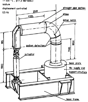
Bhandari et al. (1986) performed an experiment on a single 558.8 mm 304L stainless
steel elbow subjected to an initial crack and heated with liquid sodium at 550 °C in
order to simulate actual operating conditions. The purpose of the experiment was to
examine the fracture mechanics of the elbow while undergoing a cyclic test. An overview
37
Figure 2.14: Test frame within a safety tank (Bhandari et al., 1986).
The initial notches were located on the flanks, with one interior and the other on the
exterior. A static pre-test was performed to check the accuracy of the finite element
model stress calculations before the high temperature test was conducted. The results of
the test showed it took 70,000 cycles for the first sign of crack growth and then another
210,000 cycles before the crack depth was great enough to cause sodium leakage. The
test was ultimately concluded at 290,000 cycles. The outer flaw’s crack development
agreed well with the model’s predictions, however, the inner flaw’s crack development
38 A study of pipe elbow deformation behavior was conducted by Hilsenkopf et al. (1988) A
comprehensive set of tests were performed on ten ASME SA 106 grade B ferritic steel
elbows and fifteen ASME TP 304L stainless steel elbows consisting of in-plane bending
and out-of-plane bending where some tests included either pressure, preliminary
cycling, or an increased temperature to 120 °C. A diagram of the test setup is shown in
Figure 2.15.
39 The results of the tests showed that the deformations observed did not impact flow
capacity and that the elbows exhibited high ductility. The preliminary cycling was
shown to decrease elbow strength and quicken the transition from elastic to plastic. The
elevated temperature also decreased elbow strength for in-plane closing and
out-of-plane bending but did not have much effect on in-out-of-plane opening (Hilsenkopf et al.,
1988).
Ueda et al. (1990) was concerned with thermal stress ratcheting, where progressive
deformation can be found in situations of cyclic temperature distribution. The specific
area of focus was in LMFBRs, where liquid sodium is used as the coolant in the primary
and secondary piping systems. However, the investigators noted that while there were
some experiments on straight pipes and bars, there were few experimental works on the
ratcheting behavior of piping elbows. The investigators composed a test of an elbow
specimen in order to observe the ratcheting effect under primary and thermal cyclic
loads. The test specimen was comprised of three 76.2 mm 304 stainless steel long radius
40
Figure 2.16: Diagram of test specimen (Ueda et al., 1990).
The specimen was then welded to a sodium piping loop. A constant axial load was
applied through a dead weight loader. Thermal loading consisted of cycles of 550 °C
(hot) and 350 °C (cold) sodium flows. The hot and cold flowed for 5 minutes, respectively
and the cycle period was 10 minutes. The tensile axial load was increased in a stepwise
manner with 100 thermal cycles per step. The sodium flow rate was a constant 0.7 m/s.
The test results showed a progressive deformation of the elbow cross section which could
be divided into transient ratcheting behavior followed by a steady state ratcheting
behavior at each axial load level. At the lower axial load levels, however, the transient
ratcheting converged to zero ratcheting after about 15 – 30 cycles. The authors
concluded that the presence of transient ratcheting was due to stress redistribution and
41
2.4
Summary of Previous Work
A comprehensive history of experimental studies is described here in seriatim. Markl
(1952) published a comprehensive study on the fatigue life of a multitude of piping
components under in-plane and out-of-plane cyclic bending. The ASME design code later
incorporated the results and ultimately formed the basis of many design provisions.
Later, Edmunds and Beer (1961) published a paper on ratcheting and shakedown while
investigating fatigue failure. The next few decades saw studies that focused on specific
areas in piping components. Greenstreet (1978) and Suzuki and Nasu (1989) performed
experiments that examined plastic collapse. Other areas included studies on stress
corrosion failure (NUREG-75/067, 1975) and plastic fatigue analysis (Tagart, 1972,
Rodabaugh & Wood, 1998). Then, in 1990s EPRI (General Electric Nuclear Energy,
1994) undertook a massive experimental program examining fatigue failure of piping
components used in nuclear power plants due to seismic or other dynamic loadings. The
failure mode observed in the tests was fatigue ratcheting, instead of plastic collapse as
written in the earlier ASME design code. Testing performed at around the same time by
other investigators also confirmed the EPRI results by investigating the fatigue
ratcheting failure mechanism (Acker et al., 1992, Yahiaoui et al., 1996). This result
prompted research into code change recommendations (Tagart et al., 1990, Garud et al.,
1993, Chen et al., 1995). In addition, the attention prompted further research (Hwan &
Ranaganth, 1995, Zhao et al., 1995). Boussaa et al. (1994) conducted a review of three
dynamic tests performed at ERPI (1994) and completed a fatigue life analysis as set
42 radius elbows was carried out by Sakai et al. (1995). The authors noted that the
experiment was necessary at the time because of a lack of data on short radius elbows.
Since the advent of the fatigue ratcheting failure mechanism, research has been ongoing
in order to understand the phenomenon. Suzuki et al. (2002) conducted an experiment
on piping components including elbows in order to devise a simplified piping model. Also
Miyazaki et al. (2002) performed an experiment on a piping system where pipes were
subjected to local wall thinning. Chen et al. (2006) published an experiment specifically
on examining ratcheting in carbon steel elbows. Additionally Karamanos et al. (2006)
focused on producing a finite element model to analyze the nonlinear elastic-plastic
behavior of pressurized elbows. An experiment was performed for comparison.
Takahashi et al. (2010) conducted an experiment on pipe elbows subjected to local wall
thinning under low-cycle fatigue. Experimental work performed by Varelis et al. (2013)
investigated the low-cycle fatigue under various cyclic loadings. This work was recently
continued, where Varelis and Karamanos (2014) conducted pressurized elbow tests in
order to compare with the previous unpressurized tests.
In terms of high temperature tests, the number of experiments conducted are far fewer.
Heald and Kiss (1974) were concerned with the ASME design code with respect to
nuclear power plants and cyclic loading. They carried out an experiment on 26 piping
components that included internal pressure and high temperature. Griffith and
Rodabaugh (1975) performed an experiment on a long radius elbow under high
43 experiment on a stainless steel elbow with an initial crack and filled with liquid sodium
in order to examine the fracture mechanics during cyclic loading. Hilsenkopf et al.
(1988) executed experiments on 25 elbows that included an elevated temperature level
subjected to in-plane or out-of-plane bending. Finally, Ueda et al. (1990) were concerned
with thermal stress ratcheting in elbows used in LMFBRs. They performed a test on
long radius elbows welded together and connected to a liquid sodium loop.
The review of the literature has shown that there are few experimental studies that
address elbow failure due to low-cycle fatigue, especially with respect to short radius
elbows. Such studies have raised the concern of ratcheting and its effect on the fatigue
life of elbow components. In addition, code committees around the world are revisiting
their respective design codes in order to account for ratcheting. An examination of the
piping elbow studies on the topics of ratcheting, including thermal ratcheting and
shakedown, fatigue failure responses, and constitutive modeling have shown that the
effect is still not suitably predicted by advanced finite element models (Chen et al.,
2013). The literature contains even less experimental data on the behavior of elbows at
high temperatures under low-cycle fatigue. Such data is critical in cases such as nuclear
power plants, as their piping systems will be exposed to elevated temperatures during
normal operation. Without experimental data at those temperatures, it will be difficult