Transactions of the 17th International Conference on Structural Mechanics in Reactor Technology (SMiRT 17) Prague, Czech Republic, August 17 –22, 2003
Paper # B02-1
Nonlinear Stability Analysis of Doublet Type Thin-walled Shell Structures
Considered the Multi Point Constraints Condition
Kyung-Ho Yoon*, Myung-Hwan Choi*, Hyung-Kyu Kim* and Kee-Nam Song*
*Korea Atomic Energy Research Institute
ABSTRACT
The objective of this research is to evaluate the plastic buckling behavior of the thin plate grid structure. To perform this objective, two kinds of approaches are taken in this work. First, in order to obtain the test data on the dynamic failure behavior of the grid, an impact test is performed with a 8×8 cell size partial grid specimen, which is made of Zircaloy-4 thin plate. Second, a finite element (FE) analysis method for predicting the buckling behavior on the spacer grid structure is established by a commercial FE code ABAQUS/explicit. In this FE analysis method, appropriate boundary conditions and impact loading conditions are applied to simulate the actual test conditions. The dynamic impact analysis is performed to evaluate the plastic buckling behavior of a grid structure under the lateral impact load. The FE model is produced using pre-processor I-DEAS, and solved using nonlinear commercial solver ABAQUS/explicit. In this work, a FE model is created using the multi-point constraint (MPC) conditions. Applied boundary conditions for dynamic impact analysis were almost the same as the actual boundary conditions for the impact test. This FE model will be compared with test results. The plastic buckling behavior of a thin-plate structure is dependent on the external impact velocity of the hammer. In addition, the dynamic buckling behavior of a thin-plate structure is gradually continued due to the internal impact energy absorption.
Key Words : Spacer Grid Structure, Lateral, Impact, Energy absorption, Pressurized water reactor fuel,
plastic deformation, Local buckling, critical impact velocity
INTRODUCTION
Inserted thin plates compose the grid structure and then laser welded at the cross-points and the connection points of the inner/outer plates. The boundary condition (bc) of this structure is that one surface is simply supported, and the other surface is imposed for the impact load in a lateral direction. The critical impact velocity and force are important parameters for evaluating the integrity of the structure under the above boundary condition.
In this work, FE analysis is established for predicting the plastic buckling behaviour of the multi-cell grid structure under the lateral impact loading. The main purpose of this is to develop the finite element analysis model for predicting the impact test behaviour. In previous work [1], it is mainly dependent on the direct impact test, however, it needs recursively testing for the change of the boundary condition and geometry of the structure. The current considered FE model is a multi-point constraints model case, in which all the slit edges are actually separated with translational and rotational degree of freedom (dof) [2, 3].
The FE model was created with 4-node shell element, rigid and mass element using I-DEAS [4]. ABAQUS/explicit commercial code [5] was used for solver. The FE analysis procedure is supposed, an impact hammer is modeled as the rigid element, which has equivalent mass with their hammer. The external impact load is modeled on the initial impact velocity at the reference node of the upper rigid surface, which is located in the centre. The FE analyses results are investigated by impact acceleration, velocity, force and deformed shape.
FINITE ELEMENT ANALYSIS
Geometric Data
The outline geometric data of the model was 103×103×40 mm, the thickness of inner and outer thin plate were
Material Properties
The material of plate is Zircaloy-4, its elastic modulus is 108.3 GPa, yield strength is 344.3 MPa, density is 6550 kg/m3, and Poisson’s ratio is 0.294. The buckling behavior of the grid structure was considered to be the plastic
buckling phenomena, therefore the mechanical properties of the material had to be considered in the piece-wise linear elastic-plastic characteristic curve. So, the uni-directional tensile test of the material was accomplished as ASTM [6]. The elastic-plastic material properties of it were summarized and the true stress and strain data of that was converted from engineering stress and strain data as shown in Figure 1 [6].
0 100 200 300 400 500 600
0 0.05 0.1 0.15 0.2 0.25
Strain
Stress(MP
a
Figure 1: True stress vs. true strain curve of Zircaloy-4 sheet metal from tensile test [6]
Finite Element Model
In Figure 2, the number of nodes and the number of elements of the FE model is 51659 is 39587 for the grid structure, respectively. The three kinds of elements are used for the FE model. The four nodes shell element is for structure of thin plate structure, the four node rigid elements are used for impact hammer and base, and the mass element for define the mass of hammer. The FE model is depicted in Figure 2.
In this FE model, two rigid elements are used. The upper one is for hammer and the lower one is for base during impact event. The contact surface between lower surface of the structure and base is no gap. The other contact surface between upper face of the structure and impact hammer is a little distance for avoiding the initial over-closure between them.
(a) isometric view (b) front view Figure 2: FE model of 8 by 8 grid structure.
Analysis Procedure
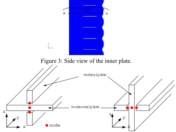
In this model, the external force was modelled by initial impact velocity at the centre node of the upper rigid surface, and the output values for the initial impact velocity could be obtained at this node. The actual test conditions were applied to the boundary conditions for analysis. The lower rigid surface is constrained in all degrees of freedom, and two diagonal nodes of the bottom surface are constrained in x-translational degree of freedom for protecting the rotational motion. The above boundary condition is depicted in Figure 2(b). The entire analysis time is 10 ms, and the increment storing time is 1 ms. Therefore, the total analysis results are stored 10 times. Because these dynamic analyses results included the noise, the appropriate filtering is needed for eliminating the noise from the raw data. In this work, SAE filtering is used for this, which is for high frequency noise. The schematic drawing of the inner plate is shown in
upper
rigid (hammer)
lower rigid (base) structure
pipe
nodes at the same position have complexly activated by the external impact load. MPC means the general multi-point constraints condition. All inner edges have to be modelled as a MPC condition, because they are not one body. In region A of Figure 3, the three degrees of freedom of vertical plates are constrained in z-translational and x and y rotational direction. Similarly, in region B, the three dofs of horizontal plates are constrained in x-translational and y and z rotational direction. Therefore, the linear constraint equations are used to simulate the split edges. These linear constraint equations are as follows.
In region A,
1 2
1 2
1 2
0 0 0
V A V A
Z Z
V A V A
ROTX ROTX
V A V A
ROTY ROTY
u u
u u
u u
− =
− =
− =
(1)
In region B,
1 2
1 2
1 2
0 0 0
H A H A
X X
H A H A
ROTY ROTY
H A H A
ROTZ ROTZ
u u
u u
u u
− =
− =
− =
(2)
Superscript V means the vertical plates, and H means the horizontal plates. And subscript Z, ROTX, ROTY, X, and ROTZ mean the dofs in global coordinate.
A B
Figure 3: Side view of the inner plate.
y
horizontal plate vertical plate
x z
x z
y y
node
Figure 4: Restriction at connecting parts between vertical and horizontal plates.
In addition to this, the welding bead is thicker than the inner/outer plates as in Figure 5, and they performed the rigid body motion. According to this, these welding beads are modelled with beam elements as per their size. Except for these considerations, all of the modelled conditions are the same as those of the simplified model.
W elding bead (6 points node)
Analysis Results
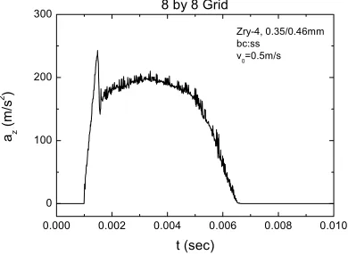
As described previous paragraph, the plastic buckling parameters were obtained at the centre node of the upper rigid surface. The maximum acceleration of the FE model at the initial impact velocity is changed to initial impact velocity [2]. Therefore, the critical impact acceleration of the model is decided to be the maximum value. In Figure 6, the maximum acceleration as initial velocity is approximately 243.0 m/sec2, and the critical impact force is 5710.5 N,
respectively.
0.000 0.002 0.004 0.006 0.008 0.010 0
100 200 300
Zry-4, 0.35/0.46mm bc:ss
v0=0.5m/s
8 by 8 Grid
az
(m/s
2 )
t (sec)
Figure 6: Acceleration time history of 8 by 8 grid structure at v0=0.5m/s from FE analysis.
Figure 7: Deformed shape of grid structure at v0=0.5m/s and t=4ms from FE analysis.
0.000 0.002 0.004 0.006 0.008 0.010 0
100 200
300 8 by 8 Grid
az
(m/s
2 )
t (sec)
v-03 v-04 v-05 v-06 v-07
Figure 8: Acceleration time history of 8 by 8 grid structure from FE analysis.
ASSESSMENT OF PLASTIC BUCKLING
Initial Impact Velocity vs. Maximum Acceleration
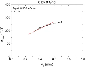
The maximum impact acceleration was increased as initial impact velocity from FE analysis, but it was decreased as initial impact velocity from test. It was caused by decrease of the stiffness due to the repeated impact loading. However, it was not possible to exalt the reduction of the structural stiffness. Therefore, the slope of this was changed at the Cardinal point. There was little different pre-value with post-that critical point. This phenomenon is generally considered to proceed the plastic buckling of the structure results in a local buckling.
The buckling behavior of the thin-plate structure is occurred at the weakest cell of the structure. Because of the exceed impact energy is concentrated at the weakest place of the whole structure. Therefore, the plastic deformation was initiated from this point, and reached the global buckling shape. For the lateral impact of rectangular tube cell array structure, the critical parameters are very different with column’s case. Most of these cases, the critical values are no certain. In Figure 9, the variation point was regarded the critical value.
0.0 0.2 0.4 0.6 0.8 1.0
0 100 200 300 400
Zry-4, 0.35/0.46mm bc : ss
8 by 8 Grid
ama
x.
(m
/s
2 )
v0 (m/s)
Figure 9: Maximum impact acceleration of the 8 by 8 grid structure from FE analysis.
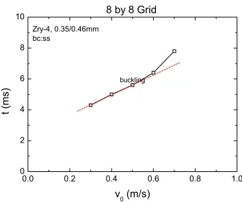
Duration Time vs. Initial Impact Velocity
0.0 0.2 0.4 0.6 0.8 1.0 0
2 4 6 8 10
buckling
8 by 8 Grid
Zry-4, 0.35/0.46mm bc:ss
t (ms
)
v0 (m/s)
Figure 10: Duration time of the 8 by 8 grid structure from FE analysis.
Stress and Strain
The von Mises stress contour of the exterior strap is displayed in Figure 11. The maximum stress values has occurred the mid-layer at the 3 ms of the critical impact velocity. The maximum stress is 506.7 MPa, this is above the yield stress of the material, 344 MPa.
(a) stress contour (filled plot) (b) stress contour (vector plot) Figure 11: Von Mises stress contour of the perimeter strap from FE analysis.
(a) strain (filled plot) (b) strain (vector plot) Figure 12: Equivalent strain contour of the perimeter strap from FE analysis.
In similarly, the equivalent strain contour of the perimeter strap due to the external impact load showed in Figure 12. The maximum stress at the centre node of the perimeter strap is showed in Figure 13. The residual stresses after impact event are above the yield stress of Zircaloy-4 material. It means that exceed impact velocity raised the plastic deformation inside structure. The stress values after duration time is gradually separate the yield strength 344.3 MPa.
0 2 4 6 8 10 0
100 200 300 400 500 600
Zry-4, 0.35/0.46mm bc : ss
8 by 8 Grid
σMise
s
(
M
P
a
)
t (ms)
v03 v04 v05 v06 v07 sy
Figure 13: Maximum von Mises stress of 8 by 8 grid structure from FE analysis.
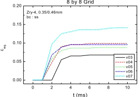
0 2 4 6 8 10
0.00 0.05 0.10 0.15 0.20
Zry-4, 0.35/0.46mm bc : ss
8 by 8 Grid
εeq
.
t (ms)
v03 v04 v05 v06 v07
Figure 14: Maximum equivalent strain of 8 by 8 grid structure from FE analysis
.Effect of Tube and Plate Connection
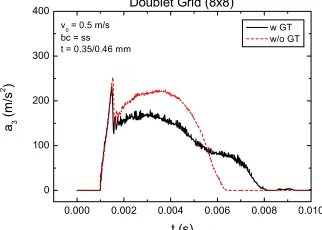
The connection of elastic pipe and thin-plate is considered. The cylindrical tubes are inserted in the center and outer position of a grid structure. These connections are composed with spring element between plate and cylindrical hollow tube. In contrary of that, the connection of the larger hollow center and outer tube and plate are made with welding process. Therefore, the effect of these differences of the connections is described in this section. The FE model without center and outer guide tube is shown in Figure 16. Besides these, all other conditions are same with Figure 2.
(a) isometric view (b) front view Figure 16: FE model of an 8 by 8 grid structure without guide tube.
The deformed shape of the excluded guide tube model is shown in Figure 17. The left side of this Figure has composed doublet strap. It is differenced with the included guide tube model. However, this little difference of the outer strap has no related with the buckling mode shape. The impact acceleration as initial impact velocity 0.5 m/sec is shown in Figure 18. The maximum impact acceleration is little higher than that of the grid structure with center and outer guide tube. It is reason that the weakest region was left side of the outer strap. The FE model for the without guide tube has composed with doublet strap, however that for the included guide tube has composed with single strap. This outer strap effect to increase the stiffness of the structure, therefore the duration time was shorter and the maximum acceleration value was higher than that of the previous model. However, the only guide tubes were nearly effect the strength of the structure. Because the impact acceleration of the included guide tube model was 233.391 m/sec2, but that of the
Figure 17: Deformed shape of the excluded guide tube grid structure at v0=0.5m/s and t=4ms from FE analysis.
0.000 0.002 0.004 0.006 0.008 0.010
0 100 200 300 400
v0 = 0.5 m/s bc = ss t = 0.35/0.46 mm
Doublet Grid (8x8)
a3
(m
/s
2 )
t (s)
w GT w/o GT
Figure 18: Acceleration time histories as included guide tube and excluded guide tube from FE analysis.
CONCLUSIONS
Finite element analyses were executed for evaluating the dynamic buckling behavior of the grid structure. From the facts described above, we concluded that the certain method for investigating the dynamic soundness of the grid structure was proposed to examine the maximum equivalent strain of it. And then the critical parameters of the dynamic buckling under the lateral impact loading were depends upon the perimeter strap of a grid. It was that the buckling behavior was likely to occur at the perimeter strap. In addition to these, there were no relate to the friction factor between two contact surfaces.
ACKNOWLEDGEMENTS
This project has been carried out under the Nuclear R&D Program by MOST.
REFERENCES
1. Y.H. Jung and K.N. Song et al., 1999, “Final Report of Development of New Fuel Rod for Pressurized Light Water Reactor”, KAERI/RR-2015/99, KAERI.
2. K.H. Yoon and K.N. Song, 2000, “Nonlinear Dynamic Buckling Analysis of a Grid Structure”, Key Engineering Materials, Vol. 183~187, pp. 451~456.
3. K.H. Yoon et al., 2000, “Nonlinear Dynamic Lateral Buckling Behavior of a Spacer Grid Structure”, Proceeding’s of the KSME Spring Meeting, Paper No. 00S044.
4. 2000, “I-DEAS Master Series”, Ver. 8m3, Structural Dynamics Research Corporation, OH, USA.
5. H.D. Hibbit, G.I. Karlsson and E.P. Sorensen, 1998, “ABAQUS/Explicit Users’ Manual (Version 5.8), Vol. I&II, RI, USA.
![Figure 1: True stress vs. true strain curve of Zircaloy-4 sheet metal from tensile test [6]](https://thumb-us.123doks.com/thumbv2/123dok_us/1606293.1198752/2.595.217.381.196.333/figure-true-stress-strain-curve-zircaloy-sheet-tensile.webp)