ISSN(Online): 2319-8753 ISSN (Print): 2347-6710
International Journal of Innovative Research in Science,
Engineering and Technology
(An ISO 3297: 2007 Certified Organization)
Website: www.ijirset.com
Vol. 6, Issue 4, April 2017
Copyright to IJIRSET DOI:10.15680/IJIRSET.2017.0604219 5934
Design and Development of Special Purpose
Machine for Drilling and Riveting Operation
Pooja Nigade 1, Prof. C.V.Patil2
P.G. Student, Department of Mechanical Engineering, S.S.G.M. Engg. College, Shegaon, Maharashtra, India1
Associate Professor, Department of Mechanical Engineering, S.S.G.M. Engg. College, Shegaon, Maharashtra, India2
ABSTRACT: The Special Purpose Machines have crucial role in manufacturing industries to enhance the productivity. In most of the manufacture processes drilling and riveting operations are performed on separate machines, consequently productivity is not efficient. Earlier work has been done by considering drilling and riveting as two distinctive processes. The modifications in drilling and riveting machines with depth controllability, multi spindle drilling head, self-pierce riveting for sheet materials, etc improved the efficiency of individual drilling or riveting machine. In this dissertation work an attempt is made to combine drilling and riveting machines to enhance the productivity. In this special purpose machine work piece are drilled on drilling spindle and then riveted on orbital riveting spindle. The spindle shaft used in this machine is critical part so design of shaft is done. Stress level of the spindle shafts obtained by analytical is less. The total time required for drilling and riveting is saved by 24.7 second per job.
KEYWORDS:Special purpose machine, orbital riveting, enhance the productivity.
I. INTRODUCTION
In developing world, performing drilling and riveting operations simultaneously on the same machine is a bigger problem for manufacturing company and workshop holders. Individual drilling and riveting machines is existing in the market, but they are not beneficial for workshop holders, small industrialist and entrepreneurs to buy separately due to very high cost. In recent past year more stress was given to design and development of existing machines. In this regard attempts had been made to develop a machine that can perform drilling and riveting operations on the individual machine. There were so many machines had been developed as portable drilling, orbital riveting machine, hand riveting, and flexible automatic riveting but there was no attempt to drilling and riveting operation on one machine. Special purpose machine (SPM) is combining the two machines which used for drilling and riveting operation separately. This machine concept provided most compact, economical and portable design which was very easy to handle and simple in operation by a single person. The machine consist of single phase induction motor transmit power to drive mechanism by pulleys through V-belt and a pneumatic cylinder which drive the process unit.
II. RELATED WORK
The finding of various scholars in the field of design, fabrication and analysis of SPM has been presented below:
P.O. Boucharda, [1] published the paper on “Numerical modeling of self-pierce riveting from riveting process modeling down to structural analysis” focused on the numerical modeling of the SPR process. They had used the finite element software to enables the model for large deformation of elastic–plastic materials for 2D and 3D configurations. A Lemaitre coupled damage model had been implemented to deal with damage during the process and fracture was modeled using the “kill element” technique. They had also check the influence of the transfer of important mechanical fields, such as residual stresses or damage, on the final mechanical strength of the riveted specimen.
ISSN(Online): 2319-8753 ISSN (Print): 2347-6710
International Journal of Innovative Research in Science,
Engineering and Technology
(An ISO 3297: 2007 Certified Organization)
Website: www.ijirset.com
Vol. 6, Issue 4, April 2017
Copyright to IJIRSET DOI:10.15680/IJIRSET.2017.0604219 5935
developing the project. The riveting machine had a rivet anvil attached to the piston of the double acting cylinder. The anvil provided the reciprocating motion by the compressed air supplied to the pneumatic cylinder at alternate ports at particular time interval. The time interval and the port through which the compressed air to be passed was controlled using electronic circuit. Also they had analysed the design for induced stresses using ANSYS software for various impact loads.
A.S. Aditya Polapragada, [3] published the paper on “pneumatic auto feed punching and riveting machine” in (IJERT). In this paper they had design and fabricate the unit and stated the importance of the pneumatic press tool had an advantage of working in low pressure, even a pressure of 6 bar was enough for operating the unit. The die used in this was fixed such that the die of required shape could be used according to the requirement. This enables them to use different type punch dies resulting in a wide range of products.
III.OBJECTIVE
1. To design the spindle shaft.
2. To analyse and compare the stress result of spindle shaft using analytical and finite element analysis tool (ANSYS).
3. To fabricate the special purpose machine
4. To compare the total time required for drilling and riveting operation for special purpose machine with existing machine.
IV.METHODOLOGY
1. Review of past drilling and riveting machines 2. Design of different parts
3. Static and modal analysis of spindle shaft 4. Modal analysis of frame
5. Fabrication of special purpose machine
6. Compare the operational time of special purpose machine with existing machines
V. DESIGN
1. Selection of Prime Mover
Given: - Diameter of hole (d) = 06 mm Thickness of plate (t) = 08 mm Drill speed (N) = 800 rpm Feed (f) = 0.2 mm/revolution
Mechanical efficiency (ƞmech) = 0.90% Solution: -
Power = . ∗ ∗ ∗ ∗( . . )
= . ∗ ∗ . ∗ ∗( . . ∗. ) = 0.1473 kW
Power of electric motor =
= 0.1473 / 0.90 = 0.164 kW
Required power of electric motor for drilling = 0.164kW.
Similarly, we can calculated power required for riveting to electric motor = 0.15 kW. Power of electric motor= Power required for drilling + Power required for riveting Power of Electric motor = 0.314 kW
According to this requirement,
ISSN(Online): 2319-8753 ISSN (Print): 2347-6710
International Journal of Innovative Research in Science,
Engineering and Technology
(An ISO 3297: 2007 Certified Organization)
Website: www.ijirset.com
Vol. 6, Issue 4, April 2017
Copyright to IJIRSET DOI:10.15680/IJIRSET.2017.0604219 5936
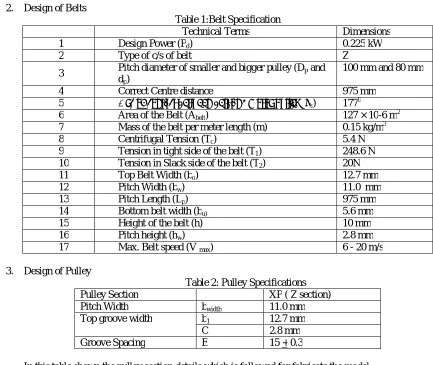
2. Design of Belts
Table 1:Belt Specification
Technical Terms Dimensions
1 Design Power (Pd) 0.225 kW
2 Type of c/s of belt Z
3 Pitch diameter of smaller and bigger pulley (Dp and dp)
100 mm and 80 mm
4 Correct Centre distance 975 mm
5 Arc of contact between belt and motor pulley (αs) 1770
6 Area of the Belt (Abelt) 127 × 10-6 m2
7 Mass of the belt per meter length (m) 0.15 kg/m3
8 Centrifugal Tension (Tc) 5.4 N
9 Tension in tight side of the belt (T1) 248.6 N 10 Tension in Slack side of the belt (T2) 20N
11 Top Belt Width (bo) 12.7 mm
12 Pitch Width (bw) 11.0 mm
13 Pitch Length (Lp) 975 mm
14 Bottom belt width (bu) 5.6 mm
15 Height of the belt (h) 10 mm
16 Pitch height (hw) 2.8 mm
17 Max. Belt speed (V max) 6 - 20 m/s
3. Design of Pulley
Table 2: Pulley Specifications
Pulley Section XP ( Z section)
Pitch Width bwidth 11.0 mm
Top groove width b1 12.7 mm
C 2.8 mm
Groove Spacing E 15 + 0.3
In this table shown the pulley section details which is followed for fabricate the model. 4. Design of Shaft
For this project shaft diameter is selected and on the basis of this selection fabricated shaft use in SPM then now check it’s safe or not.
Selected diameter of shaft Ds = 20mm Tension in tight side (T1) = 248.6 N Tension in a slack side (T2) = 20 N Diameter of pulley (DP) = 80 mm Solution:-
For this project shaft diameter is selected and on the basis of this selection fabricated shaft use in SPM then now check it’s safe or not.
Selected diameter of shaft Ds = 20mm Tension in tight side (T1) = 248.6 N Tension in a slack side (T2) = 20 N Diameter of pulley (DP) = 80 mm Solution:-
ISSN(Online): 2319-8753 ISSN (Print): 2347-6710
International Journal of Innovative Research in Science,
Engineering and Technology
(An ISO 3297: 2007 Certified Organization)
Website: www.ijirset.com
Vol. 6, Issue 4, April 2017
Copyright to IJIRSET DOI:10.15680/IJIRSET.2017.0604219 5937
= 9144N-mm Torque = 9144 N-mm Moment (M) = (T1+T2)*L = (248.6+20)* 170 =45662 N-mm
M =1
2(M + M + T )
=1
2(45662 + 45662 + 9144 )
= 46115.28 N-mm
M = π
32∗ Ϭ ∗D
= π
32∗ Ϭ ∗20
Ϭ = 58.71 /
= +
= 268.6 + 9144
= 46568.56 N-mm
T = π
16∗τ∗D
= π
16∗τ∗20
τ = 29.64 /
The value of bending stress and shear stresses are 58.71 / and 29.64 / resp. These are fewer values of stresses as compare to yield stress of shaft material.
VI.WORKINGOFSPECIALPURPOSEMACHINE
ISSN(Online): 2319-8753 ISSN (Print): 2347-6710
International Journal of Innovative Research in Science,
Engineering and Technology
(An ISO 3297: 2007 Certified Organization)
Website: www.ijirset.com
Vol. 6, Issue 4, April 2017
Copyright to IJIRSET DOI:10.15680/IJIRSET.2017.0604219 5938 Figure 1: Flow Diagram of Compressed Air
The tool is guided such that the drill is clearly projected on the required position. This force acting is passed on to drilling tool and drilling operation takes place on the workpiece. After completing the drilling operation the drill tool retracts to its original position.
After completion of drilling operation, the mechanism is used to push the workpiece at riveting tool.Then work piece is clamped by the two separate pneumatic small cylinders by passing the air from valve V5. Then a rivet is inserted on predrilled hole. The rivet tool spins about 3º – 6º offset projecting out of the joint thereby cold forming the head on the rivet side. The orbiting tool rotates at a fixed angle during orbital forming and applies both axial and radial forces to progressively move malleable material into a desired shape by passing the air from valve V3. After completing the riveting operation the rivet tool retracts to its original position.
ISSN(Online): 2319-8753 ISSN (Print): 2347-6710
International Journal of Innovative Research in Science,
Engineering and Technology
(An ISO 3297: 2007 Certified Organization)
Website: www.ijirset.com
Vol. 6, Issue 4, April 2017
Copyright to IJIRSET DOI:10.15680/IJIRSET.2017.0604219 5939
VII. RESULTANDDISCUSSION
i. Comparison of productivity of existing machines and newly design machine (special purpose machine)
Descriptions existing Machines Newly Design Machine Total time required for producing
one complete job 117.8 Sec 93.1 Sec
Job / Hour 30.56 Job / Hour 38.66 Job / Hour Job / Day 733.44 Job / Day 928.03 Job / Day Job /Month 22003.39 Job /Month 27841.03 Job /Month
Job /Year 264040.74 Job /Year 3,34,092.37 Job /Year Job MORE /Year 3,34,092.37 - 2,64,040.74 = 70,051.63 More Jobs / Year
ii. Comparison of Software result and Analytical result SR.
No.
Parameter Unit Software Result
Analytical Result
Difference (Software- Analytical)
Percentage difference
(%) 1 Bending Stress N/mm2 58.2617 58.71 0.4483 0.7635
2 Deformation Mm 0.1171 0.1092 0.007897 7.2344
iii. Discussion
The total time required for drilling and riveting is saved by 24.7 second per job .Finite Element Analysis by using ANSYS is done for validate the analytical result of shaft. From the comparison table, the validation of shaft analysis is done and stresses are less than the yield stress so shaft is safe in drilling and riveting operation.
VIII.CONCLUSION
1) It is found that the special purpose machine manufactures 70,051.63 more jobs per year as compare to existing machine.
2) Stresses in the shaft are less than yield stresses so it’s safe.
Future Scope:-
Research is the unending activity after every research some issues are come out and these issues are available for coming researchers. Here a wide scope of future research regarding with modifications, safety, utility is automatic rivet inserting mechanism can be adopted. Scope of modification is in feeding mechanism by using conveyer belt and sensor.
REFERENCES
[1] P.O. Boucharda, T. Laurenta, Tollier, “Numerical modeling of Self-Pierce riveting from riveting Process modeling down to structural analysis” , Journal of materials processing technology, Velizy - Villacoublay, France, August 2008.
[2] M. Jaivignesh, R. Harikrishnan and Dr. B.Vijaya Ramnath, “Design and performance analysis of pneumatically controlled riveting machine” Canadian Journal on Mechanical Sciences and Engineering Vol. 3 No., 3 June 2012.
[3] A.S. AdityaPolapragada, K. Sri Varsha, “Pneumatic Auto Feed Punching and Riveting Machine,” International Journal of Engineering Research and Technology (IJERT) ISSN: 2278-0181, Vol. 1 Issue 7, September – 2012.
[4] Prof. P.R. Sawant, Mr. R. A.Barawade, “Design and development of SPM - A case study in multi drilling and tapping machine,” IJAERS, Vol. I, E-ISSN2249–8974, January-March, 2012.
[5] A. M. Takale, V. R. Naik, “Design and manufacturing of multi spindle drilling head (msdh) for its cycle time optimization”, International journal of Mechanical Engineering applications research, Vol –03 ISSN: 2249- 6564 ,January-April 2012.
ISSN(Online): 2319-8753 ISSN (Print): 2347-6710
International Journal of Innovative Research in Science,
Engineering and Technology
(An ISO 3297: 2007 Certified Organization)
Website: www.ijirset.com
Vol. 6, Issue 4, April 2017
Copyright to IJIRSET DOI:10.15680/IJIRSET.2017.0604219 5940 [7] A. Manes, M.Giglio, F.Vigan, “Effect of riveting process parameters on the local stress field of a T-joint” International Journal of Mechanical Sciences, Di Milano Polytechnic, Department of Mechanical, 20156 Milano, Italy.
[8] Xiao Hong, Li Yuan, Zhang Kaifu, Yu Jianfeng, Liu Zhenxing, “Multi-objective optimization method for automatic drilling and riveting sequence planning,” Chinese journal of Aeronautics p.p.734-742, 2010.
[9] HuiChenga, Yuan Li, Kai-fuZhanga, Wei-QiangMua, Bo-fengLiub, “Variation modeling of aeronautical thin-walled structures with multi-state riveting”, The ministry of education key lab of contemporary design and integrated manufacturing technology, Northwestern Polytechnical university, China.
[10] Ian Pearson, Xiaocong He, Ken Young, “Self-pierce riveting for sheet materials: State of the art” Journal of materials processing technology, University of Warwick, UK, 2008.
[11] A.G. Hanssen, R. Porcaro, M. Langseth, A. Aalberg, “ The behavior of a self-piercing riveted connection under quasi-static loading conditions”, Department of Structural Engineering, Norwegian University of Science and Technology, Trondheim, Norway.13 December 2005. [12] N.H. Hoang, R. Porcaro, M. Langseth, A.G. Hanssen, “Self-piercing riveting connections using aluminum rivets”, International Journal of Solids and Structures, Norwegian University of Science and Technology, N-7491 Trondheim, Norway.
[13] YuhongLiua, LianhongZhanga, WeijingLiua, P.C. Wang, “Single-sided piercing riveting for adhesive bonding in vehicle body assembly”, Journal of Manufacturing Systems, China.
[14] Cubberly, W. H.; Ramon, Bakerjian, Tool and Manufacturing Engineers handbook, Society of Manufacturing Engineering SME , p.p. 42-17. [15] R. S. Khurmi, A text book of Machine Design, 14th ed., India, 2005.
[16] S. Chand Publisher, A text book of Electrical Technology, Volume – II, p.p. (228-399) , 2008.
[17] P.C. Sharma, A textbook of Production Technology and Manufacturing Processes, S. Chand publication, p.p. (90-125) , 2009. [18] V.B. Bhandari, A text book of Machine Design, Tata Mc-Graw Hill Publications, India