ISSN(Online): 2319-8753 ISSN (Print): 2347-6710
I
nternational
J
ournal of
I
nnovative
R
esearch in
S
cience,
E
ngineering and
T
echnology
(An ISO 3297: 2007 Certified Organization)
Website: www.ijirset.com Vol. 6, Issue 6, June 2017
Experimental Testing of Eclipse
Gearbox for Wind Mill Applications
Shrutika Patil
1, J. G. Patil
2M.E. Student, Department of Mechanical Engineering, SGDCOE, Jalgaon(M.S.), India1
Associate Professor, Department of Mechanical Engineering, SGDCOE, Jalgaon(M.S.), India2
ABSTRACT: Wind power is currently responsible for about 1:5% of the world’s electricity use. Because of this high interest in wind energy, it becomes more and more important to increase the efficiency of wind energy conversion systems (WECS). Such a system consists of a rotor to capture the energy in the wind, a gearbox configuration to speed up the rotational speed of the shaft and a generator to convert the mechanical energy into electrical energy. Blade pitch control is used to control the aerodynamic power captured from the wind. By pitching the rotor blades along their longitudinal axis, the aerodynamic efficiency of the rotor is changed. A disadvantage of using blade pitching below rated speed is that less energy is extracted from the wind, decreasing the efficiency of WECS. Power electronics widely used in the wind turbine industry to improve the performance of wind turbines. The biggest disadvantage of power electronics is reliability. Mechanical components show wear & tear and therefore any failures in these components can be predicted, maintenance can be scheduled before failure occurs. Unfortunately, power electronics do not show signs of degrading, therefore failures cannot be predicted and these sudden failures are very expensive to repair.
KEYWORDS: Crankshaft, Eclipse gearbox, Reliability of gearbox, Traditional gearbox, Wind turbine.
I. INTRODUCTION
ISSN(Online): 2319-8753 ISSN (Print): 2347-6710
I
nternational
J
ournal of
I
nnovative
R
esearch in
S
cience,
E
ngineering and
T
echnology
(An ISO 3297: 2007 Certified Organization)
Website: www.ijirset.com Vol. 6, Issue 6, June 2017
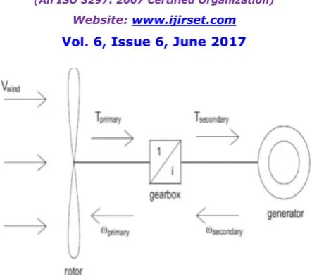
Fig. 1: Wind Energy Conversion Systems
A wind turbine extracts kinetic energy from the wind and converts this into mechanical energy.This mechanical energy is then converted to electrical energy by means of a generator. A windturbine extracts the maximum amount of energy from the wind when operating at an optimalrotor speed, which depends on the wind speed. Because the wind speed is variable by nature,the optimal rotor speed also varies. Variable speed operation ofthe rotor results in a higher energy production compared to a system operating at one constantspeed. Next to an increase in energy production, variable speed operation enables a reduction indynamic loads acting on the mechanical component. However, a problem arises whenthe speed of the rotor varies while the wind turbine must deliver AC power with a fixed phaseand frequency to the electrical grid. To match the grid requirements, current variable speed windturbines incorporate expensive power electronics to convert the variable frequency power to a constantfrequency. [1]
II. PROBLEM STATEMENT
POWER ELECTRONICS
Variable speed operation of the generator results in the production of current with a variable frequency.The frequency of the produced current is determined by the electrical angular speed ofthe generator. For the electrical grid to remain stable, the frequency and phase of all power generatingunits must remain synchronous within narrow limits. When the frequency of the generatorvaries too much, in the order of 2 Hz, circuit breakers cause the generator to disconnect from thesystem, preventing damage to the grid. However, small deviations in the generator frequency canindicate instability in the grid. The grid frequency is not exactly 50 Hz at all times, variations inthis frequency directly influence the generator frequency.
Power electronics is a technology that is developing rapidly. Higher current and voltage ratingsare available, efficiency increases and costs decrease. Therefore, power converters are widely usedin the wind turbine industry to improve the performance of wind turbines. However, there are also a number of disadvantages of using power electronics.
DISADVANTAGES OF POWER ELECTRONICS
ISSN(Online): 2319-8753 ISSN (Print): 2347-6710
I
nternational
J
ournal of
I
nnovative
R
esearch in
S
cience,
E
ngineering and
T
echnology
(An ISO 3297: 2007 Certified Organization)
Website: www.ijirset.com Vol. 6, Issue 6, June 2017
III. DESIGN OF GEARS
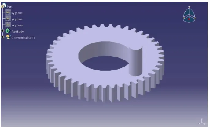
CATIAis used for design of gears.CATIA is increasingly chosen as the primary 3D design system for many companies, the worldwide demand for CATIA designers is difficult to meet. When you learn to use CATIA you also learn to work with leading-edge technology and play an important role in innovation.You get to put yourimagination to work at full-speed because with CATIA there are no boundaries.
CATIA enables the creation of 3D parts, from 3D sketches,sheet metal,composites, molded, forged or tooling parts up to the definition of mechanicalassemblies. The software provides advanced technologies for mechanical surfacing &BIW. It provides tools to complete product definition, including functional tolerances as well askinematicsdefinition. CATIA provides a wide range of applications for tooling design, for both generictoolingand mold & die.
Fig. 2: Design of Internal Gear
ISSN(Online): 2319-8753 ISSN (Print): 2347-6710
I
nternational
J
ournal of
I
nnovative
R
esearch in
S
cience,
E
ngineering and
T
echnology
(An ISO 3297: 2007 Certified Organization)
Website: www.ijirset.com Vol. 6, Issue 6, June 2017
DEVELOPMENT OF THEORY
A) System Design:
System design mainly concerns with the various physical constraints and ergonomics, space requirements, arrangement of various components on the main frame of machine, no of controls, position of these controls, ease of maintenance, scope of further improvement, etc.
B) Mechanical Design:
This part includes the design and development of linkages, selection of suitable drivemotor, strength analysis of various components under the given system of forces. In Mechanical design the components are categoriesed in two parts.
Design parts
Parts to be purchased
For design parts detail design is done and dimensions thus obtained are compared to next highest dimension which are readily available in market this simplifies the assembly as well as post production servicing work.The parts are to be purchased directly are specified &selected from standard catalogues.
C) Fabrication:
Suitable manufacturing methods will be employed to fabricate the components and then assemble the test set up. D) Testing:
Testing activity will be done with view to comment on the capability of the machine as regards tothe power transmission ability, efficiency and bearing life.
E) Facilities available:
The following facilities to carry out fabrication work are available at sponsor’s site.
Centre lathe
Milling machine
DRO – Jig Boring machine
Electrical Arc Welding
Electronic Speed Variator
Tachometer.
IV. EXPERIMENTAL RESULTS
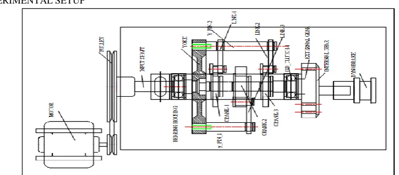
EXPERIMENTAL SETUP
ISSN(Online): 2319-8753 ISSN (Print): 2347-6710
I
nternational
J
ournal of
I
nnovative
R
esearch in
S
cience,
E
ngineering and
T
echnology
(An ISO 3297: 2007 Certified Organization)
Website: www.ijirset.com Vol. 6, Issue 6, June 2017
TESTING
For testing purpose we take low torque shaft as i/p shaft then by using motor and belt input motion is given. At other end i.e. at high torque shaft, various loads are applied and note down changes in speed at output shaft using tachometer as follows.
Result Table
Sr. No. Load (Gm) Speed (RPM) Torque (N-m) Output Power (Watts) Efficiency
1 120 2000 0.047088 9.8633664 56.36209
2 170 1875 0.066708 13.099784 74.85591
3 220 1545 0.086328 13.968993 79.82282
4 270 1390 0.105948 15.423839 88.13622
5 320 1250 0.125568 16.438944 93.93682
6 370 1030 0.145188 15.662204 89.49831
7 420 830 0.164808 14.32654 85.78766
8 470 750 0.184428 14.486819 82.78183
9 520 660 0.204048 14.104614 80.59779
10 570 595 0.223668 13.93817 79.64668
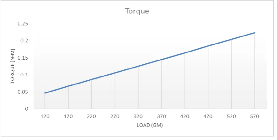
GRAPHS OF TORQUE, POWER, AND EFFICIENCY V/S LOAD
Fig. 5: Graph of Torque Vs Load
ISSN(Online): 2319-8753 ISSN (Print): 2347-6710
I
nternational
J
ournal of
I
nnovative
R
esearch in
S
cience,
E
ngineering and
T
echnology
(An ISO 3297: 2007 Certified Organization)
Website: www.ijirset.com Vol. 6, Issue 6, June 2017
Fig.6: Graph of Output Power Vs Load
Power is the rate of doing work. It is the amount of energy consumed per unit time. Figure shows the comparison of output power with load. It is seen that first with increase in load output power increases up to 16.438994 at 320 gm load. Further increase in load decreases the output power.
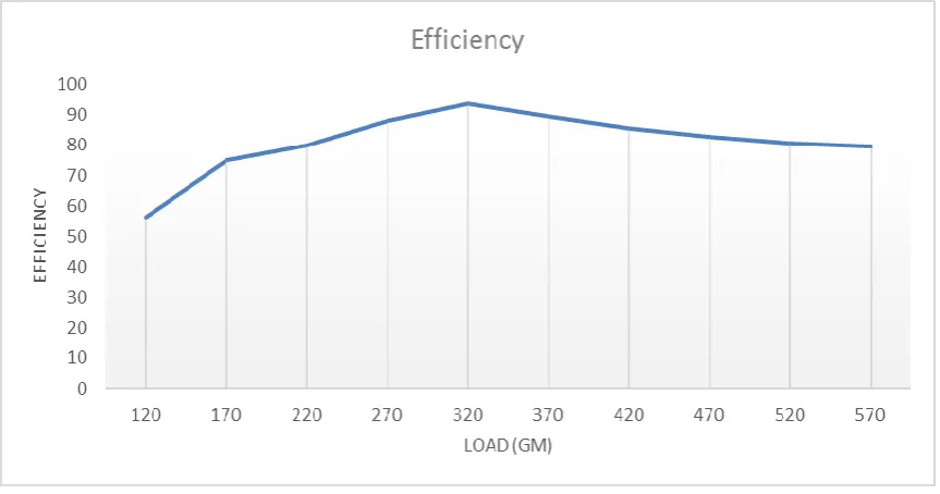
Fig. 7: Graph of efficiency Vs load
ISSN(Online): 2319-8753 ISSN (Print): 2347-6710
I
nternational
J
ournal of
I
nnovative
R
esearch in
S
cience,
E
ngineering and
T
echnology
(An ISO 3297: 2007 Certified Organization)
Website: www.ijirset.com Vol. 6, Issue 6, June 2017
V. EFFICIENCY
The mechanical design efficiency of the EclipseGearbox results in significantly greater efficiencythan traditional planetary gearboxes, due to thereduced number of energy dissipating componentsand to the fact that energy travels though only one setof gears and bearings. There are two primarycomponents that dissipate energy in a gearboxsystem: the gear tooth contact and the bearingcontact. A basic rule of thumb in gearbox design forenergy loss through gear tooth contact is approximately one half of one percent (1/2 of 1%) forevery stage of gear interaction that the energy passesthrough. Bearing contacts contribute energy lossthrough rolling motion. The linkage bearings in theEclipse are small in size in relation to traditionalgearbox bearings and rotate back and forth about 15degrees, producing only minimal energy losses. Onlythe crankshaft bearings rotate a complete 360 degreesand are similarly relatively small in size. Traditionalgearbox systems routinely suffer energy lossesamounting to four to five percent(4 – 5%) due tomultiple stage planetary gear sets and massivebearings. The Eclipse gearbox will operate with atotal mechanical efficiency of approximately95percent. Until this claim is validated by testing, aconservative estimate would be a mechanicalefficiency no less than 85 percent.
VI. ENDURANCE LIFE,SIZE AND WEIGHT
The long endurance life, small size and lightweightare the primary strengths of the Eclipse Gearbox. Itssize is equivalent to a traditional gearbox with halfthe weight. Even with half the weight, the EclipseGearbox handles greater torque loads with gears andbearings selected to handle all the requirements of themost challenging wind turbine applications, whilemaintaining endurance over a greater length of time.Gear tooth contact stress is substantially lower duethe increase in the number of gear teeth that aresimultaneously engaged. The decreased tooth contactstress directly increases the endurance life and torquecapacity of the gears.
VII. CONCLUSIONS
This work has presented a powerful method of enhancement of windmill applications by designing multistagelinkage based eclipse gearbox. Performance of windmill increases as well as the power and efficiency is alsoincreases.
The torque increases with the increase in the load. With increase in load speed decreases means torque increases with decrease in speed.
Output power indicates a rising trend up to 320 gm load and then slightly drops with further increase in load. The maximum power is obtained at 320gm load and 1250 rpm speed.
Efficiency increases with increase in load up to certain limit and after that efficiency decreases with further increase in load. The maximum efficiency of about 93 percentage is obtained at 1250 rpm speed.
All of these advantages combinedwith long endurance life and optimal efficiency, dramatically lower wind turbine operating expensesand solve the gearbox reliability problem.
REFERENCES
[1] M. J. Verdonschot, “Modeling and Control of wind turbines using a Continuously Variable Transmission”, DCT 2009.028. [2] Renewable Energy World, http://www.renewableenergyworld.com/rea/news
[3] P. C. Sen, “Principles of Electric Machines and PowerElectronics”, 2nd ed. John Wiley & Sons,1997.
[4] R. R. Salunkhe, Prof V. R. Gambhire, R. S. Kapare, “Review on Eclipse Gearbox Reliability”, IOSR Journal of Mechanical and Civil Engineering(IOSR-JMCE), ISSN: 2278-1684, PP: 27-34, www.iosrjournals.org
[5] Prof V. R. Gambhire, R. R. Salunkhe, “Eclipse Drive Train to Improve Performance Characteristics of Gearbox”,International Journal of Advanced Engineering Technology, E-ISSN 0976-3945 IntJAdvEngg Tech/IV/III/July-Sept.,2013/92-96.
[6] Terry Lester, “Solving the Gearbox Reliability Problem”, Lestran Engineering, Fort Worth, Texas, USA.