Structural Design and Stability Analysis of a
High Level Voids Bridge
Prathap. D 1, Mohammed Rafi. D 2
P.G. Student, Department of Civil Engineering, Chiranjeevi Reddy Institute of Engineering & Technology, Ananthapuramu, Andhra Pradesh, India1
Assistant Professor, Department of Civil Engineering, Chiranjeevi Reddy Institute of Engineering & Technology, Ananthapuramu, Andhra Pradesh, India2
ABSTRACT: Damage due to high flood is not limited to load resistance components such as beam and column. The majority of damage is due to breach in the building envelope such as broken deck, piers, and beams. The key geotechnical issues for design and construction of bridges include stability and settlement of the underlying soils, the impact of the stability and settlement on the construction staging and time requirements, and the impact to adjacent and nearby structures, such as buildings, bridge foundations, and utilities. Therefore, the geotechnical designer should perform a detailed site reconnaissance of the proposed construction. The study performed the Limit state design method to design the structure. The design and analysis of the sub structure and super structure of the bridge of an under construction bridge at Kondapeta were performed based on the limit state design method referred in Indian Standard codes for the design. This demonstrates that home department computer aided software is best suitable to calculate stresses and moments up to sill level. The collected soil data, hydrological data from the R & B Department, Kadapa is highly useful in the analysis of the reinforcement details of the deck which is further referred by MORTH standard designs. The detailed parts in design which have noticed during the field work are: Voided Slab Deck of 30 numbers with 20m span which will reduce the thickness and the self weight, 29 number of Hammer Head Solid Circular Piers, 10 numbers of elastomeric bearings per each pier. A strong 20 well foundations and 11 open foundations with wall Type Abutment as the soil pressure is normal have observed.
KEYWORDS:beam, column, deck, geotechnical, Kondapeta, MORTH.
I. INTRODUCTION
The definition of super structure covers the super structure of the bridge which directly takes load and transmits to the structure on either side. This is the portion spanning across the gap. In the earliest days of development of bridges, one or more timber logs were laid across the gap and some flooring arrangement provided over them, for enabling people to cross. Next development was to sling ropes across the gap and suspend from same a flooring system supported by vertical ropes for people to cross. But these types were used for mainly pedestrian traffic.
The earliest form of bridging across gaps for taking vehicles across appears to be with the use of arches extending the principle of supporting the roofs and domes in buildings of those days. Simultaneously, extensive use of timber was made by properly sizing and making a flooring system as well as supporting system. With the advent of iron, the use of masonry arches which had limitations with regard to the spans. With the development of the knowledge I structural engineering and the availability f the wrought iron and later steel, both of which can take both tension and compression equally, the use of open web girder, i.e., trusses, was developed.
II. LOCATIONANDTYPE OFBRIDGE
river and hence hydraulic study also includes in this project followed by soil parameters and traffic conditions which is collected from R&B department in Kadapa. This bridge is constructed for the passage of vehicles across Penna River. In past a cause way is constructed at this site and it is damaged.
Bridge is a structure providing passage over an obstacle without closing the way beneath. The required passage may be for a road, a railway, pedestrians, a canal or a pipe line and the obstacle to be crossed may be a river, a road, railways or a valley. various types of bridges have been constructed in the world based on the site location, material accessibility, length, usage and damaging factors such as Girder Bridge, Truss Bridge, Arch Bridge, Cantilever Bridge, Cable-stayed Bridge, Suspension Bridge, Void slab Bridge
In this project we have adopted Void Slab Bridge, as the traffic volume is less and to reduce the thickness of the slab. The void slab bridge is the answer to problems in steel concrete such as heavy weight. In this spiral tubes are inserted into the deck slab to reduce the self weight of the slab and reduce the thickness of the deck slab.
The main obstacle with the concrete constructions, in the case of horizontal slabs, is the high weight, which limits the span. For this reason major developments of reinforced concrete have focused on enhancing the span, either by reducing the weight or by overcoming concrete natural weakness in tension.
III.DESIGNWORKMETHODOLOGY
The study performed the Limit state design method to design the structure with reference to the following codes and designs assigned according to the Indian Standards:
IRC 21-2001,IRC 6-2010, IS 456-1978 clause No:25.5.1.3, clause 304.72 of IRC 21-1987,IRC-Sp-13,2004,IRC-24,IRC-15-2004,IRC 21-1999,271-MORTH, IRC 24-2001, IRC 58-2001, MORTH (third revision).
IV.EXPERIMENTAL RESULTS
A. ANALYSIS AND DESIGN OF SUPER STRUCTURE
a. Design of Voided Deck Slab:
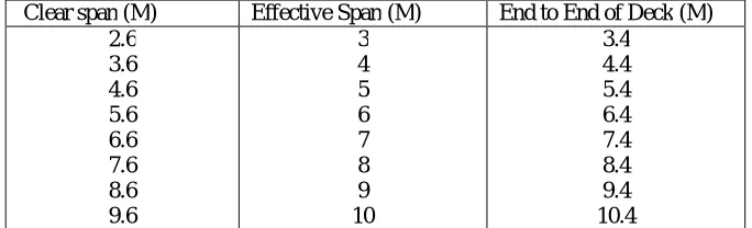
The structure above the sub structure is known as super structure. Super structure includes deck and bearings. The complete design of design and analysis of deck is given in this chapter. The reinforcement details of the deck are taken from Ministry of Road Transport & Highways (MORTH) Standard designs, where it have proposed round figures for design span(c/c of supports) in slab desck designs. With a view to avoid confusion, same nomenclature of span is considered for culverts and small bridges. The design span of 6m will have clear span of 5.60m. The values of clear span, effective span and end to end of deck for which standard designs of slab bridges are available in the following table.
Similarly type plans of MORTH are available for skew slab bridges for right effective spans of 4m,6m,8m,10m for skew angles of 15°,22.5°,30°,and 35°. Design and Analysis of voided deck is similar as RCC deck Slab.
b. Span of Deck:
Hydrological details have collected from Irrigation and R & B Department, Kadapa. Area – Chennur to Kondapeta
Bridge span-600mts River-Penna H.F.L=99.30
c. Calculation for discharge:
Mean radius R=A/P=3784.73/755.51 = 5.009mts Slope S=0.0023
Rugosity co-efficient, n=0.03 Velocity, v= ∗ ∗ =
. ∗(5.009) ∗(0.0023)
/ = 4.679m/Sec
Discharge = A*V
=3784.73*4.679 =17708.75Cumee
d. Calculation of Linear Water Way:
Discharge, Q=17708.75 H.F.L=99.3
Sill level =92.34 Velocity =4.679m/s Depth=99.3-92.34 Afflux=0.15m=x
Head due to Afflux, (ha) =( ) ∗ ∗ . = (4.679) ∗ ( . )
( . . ) ∗2∗9.81 =1.06mts
Combined Head, (ha+x) =0.15+1.06 =1.21
Velocity through vents, Vv =0.9 2 (ℎ + ) =0.9∗ 2∗9.81∗(1.21) =4.38m/sec Linear water way required,
∗ =
.
. ∗ . =580.80mts
Provide 20m span deck slab (voids deck slab) Effective span -19mts
e. Thickness of the slab: As per codal provisions for 1m span 80mm thickness is provided as deck thickness. Hence for 20m span thickness = 1760mm
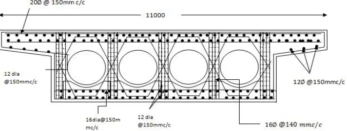
As we are adopted voided deck slab it reduces the thickness to 1290mm (reduced thickness=490mm) Deciding diameter of voids:
Provide voids of diameter ≤0.7( ℎ ℎ )= ≤0.7(1.29) = 0.90
Hence provide a thickness of 700mm or 70 cms. Width of the deck = 7.5m+2 footpaths and railings Hence adopt a width of 11.1m
Lane width = 7.5m
Provide void to void c/c distance = 1.1m
Clear gap between voids = 400mm (referred from MORTH designed) Hence provide 4 voids of 700mm dia and 0.1mm thickness with 400mm clear cover. Self weight of the deck = weight of deck +weight of footpaths+ weight of railings = (7.5*20*1.29*24) + (0.07*22) +129.5 = 4788.9KN Reduce voids concrete volume from total load= ℎ ∗24 = 738.9
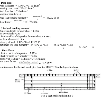
f. Dead load:
Deck thickness = 1.294*27=31.05 kn/m2 Wearing coat = 0.1*22=2.2 kn/m2 Total dead load =33.16 kn/m2 Length of span L=21.2
Dead load bending moment = . ∗ . = 1862.92 kn-m Shear force= . ∗ . = 351.496 KN.
g. Live load bending moment:
Dispersion length for one wheel = 1.13m For two wheels =2.33
Effective width of dispersion for one wheel = 3.63m For four wheels= 8.115m
Intensity of load= 1.44*4*144/8.115*2.33 Maximum live load moment =
h. Shear Force:
Effective width of dispersion = 2.325m Effective width for 4 wheels = 7.463m
Intensity of loading = load/area = 37.76Kn/sqm Max shear force=
Reinforcement for the deck is adopted from the MORTH Standard specifications.
Fig. 2 Sectional detail along B-B The above figure showing the sectional details of the deck along the section B-B.
Fig.3 Sectional detail along A-A The above figure showing the sectional details of the deck along the section B-B
m
KN
2 93.3
Fig. 4. Section showing Mesh Reinforcement at Bearing & Jack Locations
Fig. 5 Cross sectional detail at support The above figure showing the cross sectional details of the deck along the section B-B. Reinforcement for the deck is adopted from the MORTH Standard specifications
B. DESIGN DETAILS OF BEARINGS
a. Selected type of bearing: Elastomeric Bearing. Total dead load reaction = 351.496KN
Total live load reaction = 140.132 KN Longitudinal forces per bearing=12KN Total reaction = 503.62 KN
Plank size = 400*250 mm Take A1/A2 = 2
Allowable contact pressure =
= 8.83 Mpa Effective area = 57.03∗10
hi = 10 mm hs = 3mm he =5mm Side = 6mm
Adopt 4internal layers and 5 Ms laminates. h= 65mm
Bearing pedestal size = 700*500*235mm General provision of pedestal thickness = 235mm
Fig: 7Elastomeric Bearing Details
Fig:8 Reinforced Details Of Pedestal. 2
1 25 . 0
C. DESIGN AND ANALYSIS OF PIER
a. DESIGN OF PIER
Design of pier includes design of hammer head and the design of the pier.
b. Hammer Head:
Fig: 9 Top view of hammer head.
Fig: 10 Bearing details on the head
Deciding length and width of the hammer: Slab total length =20m
Road crest level=101.9m
Bottom of deck= 101.9-1.294-0.075 = 100.53m Adopt bearing dimensions = 400*250*65 Provide bearing pedestal size = 550*700*235mm
Width of hammer head=120+150+125+1000+125+150+120=1790mm Provide a width of 2100mm for safety.
Length of hammer head= 5.5m
Provide hammer overall thickness =1.2m Total live loads & dead loads reaction:
i. Dead load:
Deck thickness = 1.294*27=31.05 kn/m2 Wearing coat = 0.1*22=2.2 kn/m2 Total dead load =33.16 kn/m2 Length of span L=21.2
Dead load bending moment = . ∗ . = 1862.92 kn-m Shear force= . ∗ . = 351.496 kn.
ii. Live load:
L.L = 1090 KN
Dispersion length= w+2h=1.5+2(0.1) =1.7 Bes = αx 1− +b1
= 10.57
Dispersion width= 2.64+ . +1.2+ . +2.64 = 7.8 Effective length = 3+2(0.1+1.29)
= 5.78 m Intensity = = . ∗ . = 13.22 kn/m2 Live load B.M = . ∗ . = 742.66 kn-m Shear force = . ∗ . = 140.132 KN Total BM = 1862.92+742.66
= 2605.58 kn-m (or) 260.5 t-m Using M30 grade
V. CONCLUSION
The design and analysis of the sub structure and super structure of the bridge of an under construction bridge at kondapeta were performed based on the limit state design method referred in codes IRC 21-2001,IRC 6-2010, IS 456-1978 clause No:25.5.1.3, clause 304.72 of IRC 21-1987, IRC-Sp-13,2004, IRC-24, IRC-15-2004 for the design. This demonstrates that home department computer aided software is best suitable to calculate stresses and moments up to sill level. The collected soil data, hydrological data from the R & B Department, Kadapa is highly useful in the analysis of the reinforcement details of the deck which is further referred by MORTH standard designs. The detailed parts in design which have noticed during the field work are: Voided Slab Deck of 30 numbers with 20m span which will reduce the thickness and the self weight, 29 number of Hammer Head Solid Circular Piers, 10 numbers of elastomeric bearings per each pier. A strong 20 well foundations and 11 open foundations with wall Type Abutment as the soil pressure is normal have observed. Based on the observation it is accomplished that this type of deck bridges have advantages such as reduces self weight, reduce construction time, reduce concrete usage, non-biodegradable, long term performance, predictable material behaviour and reduces the thickness of the slab.
REFERENCES
[1] IRC:6-2010. STANDARD SPECIFICATIONS. CODE OF PRACTICE FOR. SECTION : I. LOADS AND STRESSES. (Fifth Revision). Published by. INDIAN ROADS ...
[2] M. Bertalmio, G. Sapiro, V. Caselles, and C. Ballester, “Image inpainting”, in Proc. SIGGRAPH, pp. 417–424, 2000.
[3] A. Criminisi, P. Perez, and K. Toyama, “Region filling and object removal by exemplar-based image inpainting.”, IEEE Transactions on Image Processing, vol. 13, no.9, pp. 1200–1212, 2004.
[4] Marcelo Bertalmio, Luminita Vese, Guillermo Sapiro, Stanley Osher, “Simultaneous Structure and Texture Image Inpainting”, IEEE Transactions On Image Processing, vol. 12, No. 8, 2003.
[5] Yassin M. Y. Hasan and Lina J. Karam, “Morphological Text Extraction from Images”,IEEE Transactions On Image Processing, vol. 9, No. 11, 2000
[6] Eftychios A. Pnevmatikakis, Petros Maragos “An Inpainting System For Automatic Image Structure-Texture Restoration With Text Removal”, IEEE trans. 978-1-4244-1764, 2008
[7] S.Bhuvaneswari, T.S.Subashini, “Automatic Detection and Inpainting of Text Images”, International Journal of Computer Applications (0975 – 8887) Volume 61– No.7, 2013
[9] Xiaoqing Liu and Jagath Samarabandu, “Multiscale Edge-Based Text Extraction From Complex Images”, IEEE Trans., 1424403677, 2006 [10] Nobuo Ezaki, Marius Bulacu Lambert , Schomaker , “Text Detection from Natural Scene Images: Towards a System for Visually Impaired
Persons” , Proc. of 17th Int. Conf. on Pattern Recognition (ICPR), IEEE Computer Society, pp. 683-686, vol. II, 2004
[11] Mr. Rajesh H. Davda1, Mr. Noor Mohammed, “ Text Detection, Removal and Region Filling Using Image Inpainting”, International Journal of Futuristic Science Engineering and Technology, vol. 1 Issue 2, ISSN 2320 – 4486, 2013