ISSN(Online): 2319-8753 ISSN (Print): 2347-6710
I
nternational
J
ournal of
I
nnovative
R
esearch in
S
cience,
E
ngineering and
T
echnology
(An ISO 3297: 2007 Certified Organization)
Website: www.ijirset.com
Vol. 6, Issue 8, August 2017
Automatic Delivery Bot using RF
Communication
M. Sivanesh 1, Mohammad Afridi 2, Mohammad Shandar 3, Nowzish M4 and Praveen Kumar M5
U.G. Students, Department of Electronics and Communication Engineering, Sahyadri College of Engineering and
Management, Adyar, Karnataka, India1,2,3,4
Assistant Professor, Department of Electronics and Communication Engineering, Sahyadri College of Engineering and
Management, Adyar, Karnataka, India 5
ABSTRACT: It’s a four wheeled local delivery robot which could be widely used in almost all kind of building cover a great distances within the floor limit. It delivers things from a ‘Local Delivery Point’ to every classroom, control room, laboratories, meeting hall, seminar hall, etc. making a successful delivery to necessary person or staff or student. The overall performance is based on Arduino Mega 2560 microcontroller which controls other the robot and automatically decides the shortest path for the robot to reach the destination.
KEYWORDS:H-Bridge concept, RF communication, Obstacle avoidance and Buzzer alarm. I. INTRODUCTION
The purpose of this research is to realize a delivery robot robust with the unknown object in indoor environment. In recent years, in order to raise the working efficiency in a production site like a factory the work support by the robot which carries goods automatically is called for. A delivery robot is running the path determined and has been successful in the industrial field.
Today when any faculty or research person or board meeting members or doctors or factory worker wants something in between of his work, they get their task done by any student or any lower authorities. With this robot we can make deliveries less than 2 minutes from local delivery point or to destination.
We are introducing new concept called as “Push to Deliver System”. As the name suggests, on the push of a button we instruct the robot to automatically deliver our necessary. The robot automatically detects the incoming signal and analyses from where the signal is sent. An inbuilt code runs based on the call of the control room to decide the shortest path to reach the destination.
Once the robot has reached the destination, it gives a buzzing sound to indicate the person of his arrival. Once the delivery is done, it comes back its original position (Local delivery point). And so on the it monitors any incoming signal and accordingly delivery is done.
II. LITERATURE SURVEY
Mobile Robot in Hospital
ISSN(Online): 2319-8753 ISSN (Print): 2347-6710
I
nternational
J
ournal of
I
nnovative
R
esearch in
S
cience,
E
ngineering and
T
echnology
(An ISO 3297: 2007 Certified Organization)
Website: www.ijirset.com
Vol. 6, Issue 8, August 2017
III.PROPOSED METHODOLOGY AND DISCUSSION
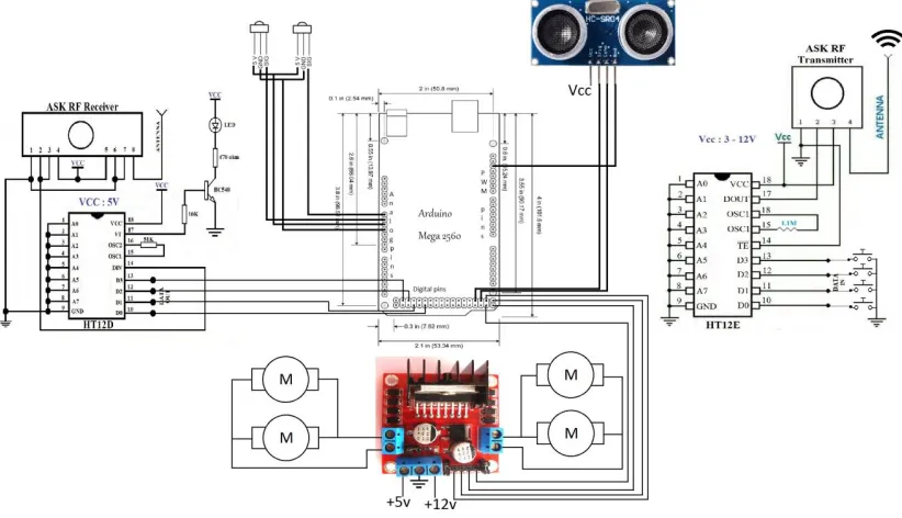
This project is based on transmission of different signals from different control rooms and receiving and analysing in the receiver end. The code automatically detects the incoming signal and maps it with the shortest path to the room as previously coded. Meanwhile, in the background ultrasonic sensor also constantly monitors objects in the path to destination. In the Fig 1, control 1, control 2, … control 5 are the different rooms (may be in different corner of the floor) all send signal with just a push of a button placed in every room.
FIG. 1 BLOCK DIAGRAM OF TRANSMITTER CIRCUIT FIG. 2 BLOCK DIAGRAM OF RECEIVER CIRCUIT
ISSN(Online): 2319-8753 ISSN (Print): 2347-6710
I
nternational
J
ournal of
I
nnovative
R
esearch in
S
cience,
E
ngineering and
T
echnology
(An ISO 3297: 2007 Certified Organization)
Website: www.ijirset.com
Vol. 6, Issue 8, August 2017
Ultrasonic Sensor: The Ultrasonic Sensor sends out a high-frequency sound pulse and then times how long it takes for the echo of the sound to reflect back. The sensor has 2 openings on its front. One opening transmits ultrasonic waves, (like a tiny speaker), the other receives them, (like a tiny microphone).
The speed of sound is approximately 341 meters (1100 feet) per second in air. The ultrasonic sensor uses this
information along with the time difference between sending and receiving the sound pulse to determine the distance to an object. It uses the following mathematical equation:
Distance = Time x Speed of Sound divided by 2
Time = the time between when an ultrasonic wave is transmitted and when it is received You divide this number by 2 because the sound wave has to travel to the object and back.
Fig. 4 Ultrasonic sensor module Fig. 5 Working of ultrasonic sensor module
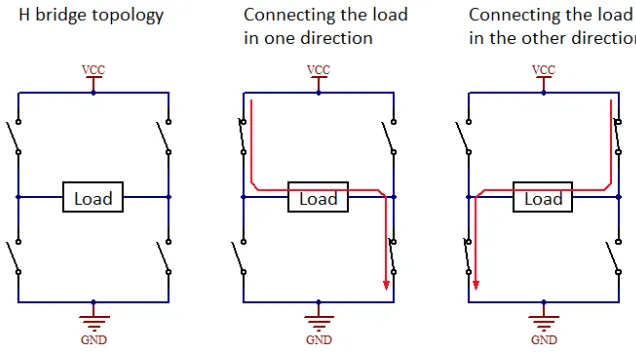
H – Bridge concept: An H bridge is an electronic circuit that enables a voltage to be applied across a load in either direction. These circuits are often used in robotics and other applications to allow DC motors to run forwards or backwards.
Most DC-to-AC converters (power inverters), most AC/AC converters, the DC-to-DC push–pull converter, most motor controllers, and many other kinds of power electronics use H bridges. In particular, a bipolar stepper motor is almost invariably driven by a motor controller containing Two H Bridges.
ISSN(Online): 2319-8753 ISSN (Print): 2347-6710
I
nternational
J
ournal of
I
nnovative
R
esearch in
S
cience,
E
ngineering and
T
echnology
(An ISO 3297: 2007 Certified Organization)
Website: www.ijirset.com
Vol. 6, Issue 8, August 2017
Fig. 7 L298 motor driver Fig. 8 L298 IC pinout
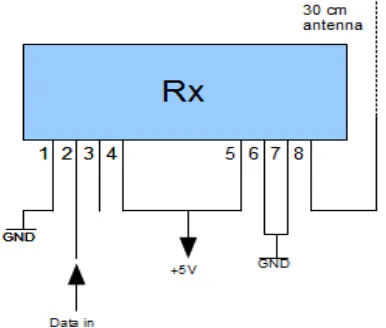
RF Communication: To receive radio signals an antenna must be used. However, since the antenna will pick up thousands of radio signals at a time, a radio tuner is necessary to tune into a particular frequency (or frequency range). This is typically done via a resonator – in its simplest form, a circuit with a capacitor and an inductor form a tuned circuit. The resonator amplifies oscillations within a particular frequency band, while reducing oscillations at other frequencies outside the band. The distance over which radio communications is useful depends significantly on things other than wavelength, such as transmitter power, receiver quality, type, size, and height of antenna, mode of transmission, noise, and interfering signals. Ground waves, tropospheric scatter and skywaves can all achieve greater ranges than line-of-sight propagation. The study of radio propagation allows estimates of useful range to be made.
ISSN(Online): 2319-8753 ISSN (Print): 2347-6710
I
nternational
J
ournal of
I
nnovative
R
esearch in
S
cience,
E
ngineering and
T
echnology
(An ISO 3297: 2007 Certified Organization)
Website: www.ijirset.com
Vol. 6, Issue 8, August 2017
Fig. 10 transmitter and receiver module
Carriage section: It is the section of the robot where it can hold the required things up to 550g to 600 g of mass. To improve carriage capacity, high torque motors ought to be used with bigger in size of robots and thereby resulting in more capacity.
IV.EXPERIMENTAL RESULTS
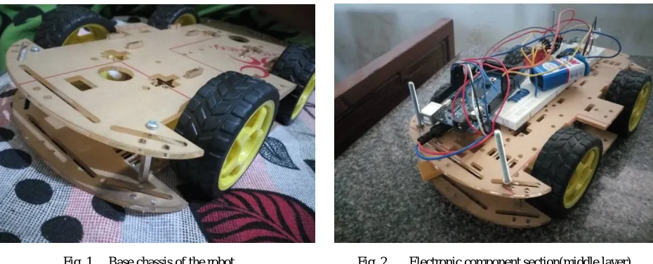
Fig. 1 Base chassis of the robot Fig. 2 Electronic component section(middle layer)
In Fig 14, the transmitter consists of 4 different control room push buttons (for simplicity it is shown in a single board) along with HT12E IC, which is encoder IC which works with a low signal on the TE pin. After receiving a low signal the HT12E starts the transmission of 4 data bits. And the output cycle will repeats based on the status of the TE pin in the IC. If the TE pin retains the low signal the cycle repeats as long as the low signal in the TE pin exists. The encoder IC will be in standby mode if the TE pin is disabled and thus the status of this pin was necessary for encoding process. The address of these bits can be set through A0 – A7 and the same scheme should be used in decoders to retrieve the signal bits.
ISSN(Online): 2319-8753 ISSN (Print): 2347-6710
I
nternational
J
ournal of
I
nnovative
R
esearch in
S
cience,
E
ngineering and
T
echnology
(An ISO 3297: 2007 Certified Organization)
Website: www.ijirset.com
Vol. 6, Issue 8, August 2017
Fig. 3 Bottom layer for motors and motor driver Fig. 4 Transmitter
Fig. 3 Here we have four 3v DC motors connected to L298N motor driver in parallel connection in order code the motors with H-Bridge concept. Fig. 4 is a transmitter circuit which consists of one HT12E IC connected to transmitter module. Four toggle switches represent the four different buttons from different control room. Slide switch is connected to activate the transmitter circuit.
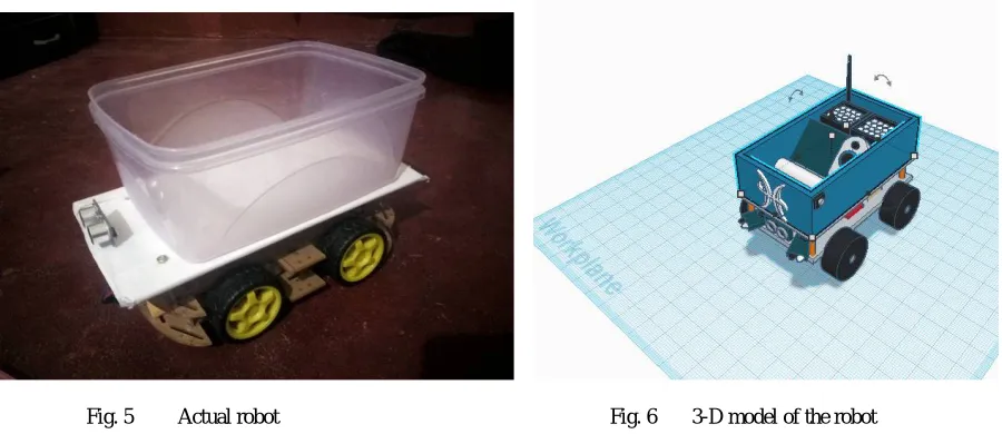
Fig. 5 Actual robot Fig. 6 3-D model of the robot
Fig. 5 This is the real make of the robot with ultrasonic sensor mounted in front and carriage section of volume 25cmx18cmx15cm. Fig. 6 is the actual cad work done before the make of the robot.
Improvement to Project: Robots can take steps only if wheels are replaced with stair climbing wheels (as shown in Fig. 7) with additionally attached gears. But in this case we need to take care of balance of the carriage section from being tilted forwards or backwards. However, wheels attached with basic spring system could solve the tilt of carriage section.
ISSN(Online): 2319-8753 ISSN (Print): 2347-6710
I
nternational
J
ournal of
I
nnovative
R
esearch in
S
cience,
E
ngineering and
T
echnology
(An ISO 3297: 2007 Certified Organization)
Website: www.ijirset.com
Vol. 6, Issue 8, August 2017
Fig. 7 Design of robot with stair climbing wheels Fig. 8 CAD design of the robot with stair climbing wheels
V. CONCLUSION
This paper proposed the control architecture of a delivery robot system for supporting staffs. We considered the medical kit delivering in hospitals and other information delivering by the robot to reduce the load of the staffs. This paper proposed the concept of a delivery robot system and its control architecture for realizing the delivering tasks with time constraint. The delivering tasks are realized based on the communication between the robot and the human. We have experiment our robot in different arena and works fine when it comes to handling with obstacles. Our algorithm successfully detects incoming signal and automatically deliveries according to desired path as coded in software. We have also verified the time constraint for delivery to be less than one minute.
REFERENCES
1.Idea from a company called Starships Technologies, https://www.starship.xyz/
2.Electronics Hub, http://www.electronicshub.org/
3.J. Evans, B. Krishnamurthy, B. Barrows, T. Skewis, and V. Lumelsky, “Handling real-world motion planning: a hospital transport robot,” IEEE Control Systems, Vol. 12, Issue 1, pp. 15-19, 1992.
4.T. Sakai, H. Nakajima, D. Nishimura, H. Uematsu, Y. Kitano, “Autonomous mobile robot system for delivery in hospital,” Matsushita Electric Works technical report, Vol. 53, No. 2, pp. 62-67, 2005 (in Japanese).
5.R. Tasaki, M. Kitazaki, J. Miura, and K. Terashima, “Prototype design of medical round supporting robot ”Terapio”,” Robotics and Automation (ICRA), 2015 IEEE International Conference on IEEE, pp. 829–834, 2015.