Seismic Analysis of Building with and Without
Infill Wall
Kiran Tidke1, Sneha Jangave2
P.G. Student, Department of Civil Engineering, Deogiri Institute of Engineering and Management Studies, Aurangabad, Maharashtra, India1
Assistant Professor, Department of Civil Engineering, Deogiri Institute of Engineering and Management Studies, Aurangabad, Maharashtra, India2
ABSTRACT: Buildings with masonry infill wall are the most common type of structures used for multi-storey constructions in the developing countries.Masonry Brick infill walls have been used in Reinforced concrete Frame structures as interior and exterior partition walls.Infill walls now a day are considered to be non-load bearing member. In the design and assessment of building, the infill walls are usually treated as non- structural element and they are ignored in analytical models because they are assumed to be non-beneficial to the structural response. Reinforced concrete framed buildings with infills are usually analysed as bare frame, without considering the strength and stiffness contributions of the infills. However during wind and earthquake these infill walls contribute some response of the structure and increase the strength and stiffness of the frame. In this paper effect of masonry infill wall on building is studied. Dynamic analysis of building with different arrangement is carried out. For analysis G+7 R.C. frame building is modelled. The width of strut is calculated by equivalent diagonal strut method. Analysis is carried by SAP2000 software. Base shear, Max.storey drift, Displacement is calculated and compared for all models.
KEYWORDS: Bare frame, Equivalent diagonal strut, Infill wall, Response spectrum, Time history analysis. I. INTRODUCTION
In multi-storey buildings, the RC frame structures are constructed initially due to ease of construction and rapid work in progress. The masonry infilled RC frame buildings are commonly constructed for commercial, residential and industrial buildings in seismic regions. Infilled frames are composite structures formed by the combination of moment resisting plane frame and infill wall. The infills are mostly used as interior partition walls and external walls which are protecting from outside environment to the building according to the requirements. The failure or collapse of buildings during earthquake is due to geological effects, poor form, inadequate design and detailing and poor quality of construction [1].The masonry infill panels are generally not considered in the design process and treated as architectural (non-structural) components. Nevertheless, the presence of masonry infill walls has a significant impact on the seismic response of a reinforced concrete frame building, increasing structural strength and stiffness (relative to a bare frame) [2].Infill reduces the lateral deflection of the building, displacement and bending moments in frame.
II. LITERATUREREVIEW
deflection eventually decreases. As the storey level of building frame increases, deflection due to lateral loads naturally increases due to additional lateral loads. Deflection increases linearly if the span of bay increases linearly because of linearly increased loads.
Dorji and D.P.Thambiratnam [4] carried out the work on ‘Modeling and Analysis of In-filled Frame Structures under seismic loads’ in which the seismic response of in-filled frame structures had been studied. In-filled frame structures are commonly used in buildings, even in those located in seismically active regions. Present codes unfortunately, do not have adequate guidance for treating the modeling, analysis and design of infilled frame structures. Finite Element time history analyses under different seismic records have been carried out and the influence of infill strength, openings and soft storey phenomenon are investigated. Results in terms of tip deflection, fundamental period, inter-storet drift ratio and stresses are presented and they will be useful in the seismic design of in-filled frame structures. Kodur, V.R.; Erki, M.A.; Quenneville, J.H.P. [5] carried out the work on ‘Seismic design and analysis of masonry-infilled frames’ in which a simple analytical procedure, which can be used by practicing engineers, for the seismic design of masonry-infilled frames is presented. The analytical procedure, based on the experimental and analytical studies reported in the literature, accounts for the effect of infills in all three stages, namely, in computing seismic loading, in predicting response of the infilled frame, and in determining the strength of the infilled frame. Seismic loading is computed using the dynamic properties of the structure. Recommendations regarding the choice of infilled frame idealization, structural damping ratio, earthquake design spectrum, structural irregularity, and computational aids are made. Application of the proposed analytical procedure in a design situation is demonstrated through a numerical example, and it is shown that infills can be accounted in the seismic design of frames during the normal course of design.
B.Srinivas and B.K.Raghu Prasad [6] discussed the effect of masonry infill walls on dynamic behaviour of structure. A five storey RC masonry infilled frame, soft first storey frame and bare frame models were selected and designed according to IS 1893 code provisions. Equivalent diagonal strut approach was used for modelling the masonry infill panels. Non-linear static and non-linear dynamic analysis was performed to study the response behavior of the building. The results shown that the presence of infill reduces the lateral deflection and increases the overall strength of the structure. The storey drift decreases due to the presence of masonry infill walls in the infilled frame but the storey drift of the soft storey is significantly large. These effects however not found to be significant in bare frame model.
Concept of equivalent diagonal strut:Investigators have proposed various approximations for the width of equivalent diagonal strut. Originally proposed by polyakov [7] and subsequently developed by many investigators, the width of
strut depends on the length of contact between wall and column αh and between the wall and beam αL shown in Fig 1. Holmes [8] recommended a width of the diagonal strut equal to one-third of the length of the panel. Stafford smith [9] developed the formulation for αh and αL on the basis of beam on an elastic foundation. The following equations are proposed
=
(1)=
4sin 2 4
(2)
Where
Em and Ef = elastic modulus of the masonry wall and frame material respectively
Ic and Ib = moment of inertia of column and beam frame respectively.
t,l = Thickness and length of the infill wall, respectively
= tan
ℎ
Hendry [10] has proposed following equation to determine equivalent strut or equivalent or effective width of strut.
Fig.1.Equivlent diagonal strut structure
Different arrangements of model:For the infill wall different location used in this paper are as follows: a) Bare frame
b) Full masonry infill wall
c) Masonry infill wall with one soft storey at ground level d) Masonry infill wall with two soft storey at ground level
III.PROBLEM DESCRIPTION
I : Building Configuration Data` Each storey height 3 m Thickness of external wall 0.23 m Thickness of internal wall 0.15 m Thickness of slab 0.15 m Thickness of parapet wall 0.15 m Height of parapet wall 1 m
Floor finish 1 kN/m2 Live load 3 kN/m2 Grade of concrete (fck) M 25
Grade of steel (fy) Fe 500
Size of beam 0.3m x 0.4 m Size of column 0.4m x 0.6 m Thickness of shear wall 0.23m Width of equivalent diagonal
strut
0.786 m
Fig.2. Plan of G+7Building IV. PERFORM ANALYSIS
Response spectrum method:The objective of response spectrum analysis is to obtain the likely maximum response of the systems. The response spectrum is a plot of the maximum response (maximum displacement, velocity, acceleration or any other quantity of interest) to a specified load function for all possible single degree-of-freedom systems. The abscissa of the spectrum is the natural period (or frequency) of the system and the ordinate is the maximum response. It is also a function of damping. The design response a spectrum given in IS 1893:2002 [12] for a 5% damped system.
Time history analysis:In order to examine the exact linear behavior of building structures, linear time history analysis has to be carried out. In this method, the structure is subjected to real ground motion records. This makes this analysis method quite different from all of the other approximate analysis methods as the inertial forces are directly determined from these ground motions and the responses of the building either in deformations or in forces are calculated as a function of time, considering the dynamic properties of the building structure. The earthquake record used to analyze the building is Imperical Valley(El Centro 1979).
V. RESULTS
Base shear:The Fig.3 shows that comparison of base shear for bare frame and for different location of infill wall. Due to provision of infill wall base shear increases. Among all the location of infill wall one soft storey infill wall shows higher base shear. From Fig.3 it is observed that provision of infill wall increases global stiffness which increases base shear.
Fig.3 Base shear for with and without infill wall
0 10000 20000 30000 40000 50000
Bare frame
Full IW
One soft storey
IW Two
soft storey
IW
B
a
se
s
h
ea
r
Base shear (KN)
The base shear of a building with and without infill wall is calculated by time history analysis method. In the time history analysis of a building with and without infill wall Imperical valley (El Centro 1979) earthquake record is used. The numerical value of the building with and without infill wall is shown in table II.
II. Base shear for with and without infill wall Model Base shear (KN) Bare frame 14770
Full masonry infill wall 39250 One soft storey infill wall 44130 Two soft storey infill wall 32250
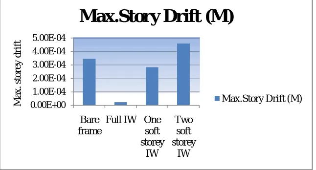
Max.storey drift :Storey drift is the displacement of one storey to the other storey level above or below [12]. The max. storey drift of building with and without infill wall is calculated by response spectrum analysis method. For the analysis of building with and without infill wall zone-II is considered in response spectrum analysis. The numerical value which is got from analysis is shown in table III.
III. Max. storey drift with and without infill wall Model Max.storey
drift (M) Bare frame 3.47 E-4 Full masonry infill wall 2.2 E-5 One soft storey infill wall 2.84 E-4 Two soft storey infill wall 4.6 E-4
The Fig.4 shows that comparison of max.storey drift for bare frame and for different location of infill wall. Infill wall reduce the storey drift. Among all the location of infill wall full infill wall shows less storey drift.As the number of soft storey increases, max. storey drift of building also increases.
Fig. 4. Maximum storey drift for building with and without infill wall
Displacement: The displacement of building with and without infill wall is calculated by response spectrum analysis method. For the analysis of building with and without infill wall zone-II is considered in response spectrum analysis. The numerical value which is got from analysis is shown in table IV
0.00E+00 1.00E-04 2.00E-04 3.00E-04 4.00E-04 5.00E-04
Bare frame
Full IW One soft storey
IW
Two soft storey
IW
M
a
x.
s
to
re
y
dr
if
t
Max.Story Drift (M)
IV. Displacement for with and without infill wall Model Displacement (M) Bare frame 0.005368
Full masonry infill wall 0.000583 One soft storey infill wall 0.001523 Two soft storey infill wall 0.002921
Fig.5 shows the displacement of building with and without infill wall. Infill wall reduce displacement of building.Among all the location of infill wall full infill wall shows less displacement. As the number of soft storey increases, displacement of building also increases.
Fig.5. Displacement for with and without infill wall VI. CONCLUSION
In this study, Response spectrum and time history analysis were performed for G+7 RC frame structure with masonry infill wall and shear wall frame at their different location. The infill walls were modelled as equivalent diagonal strut. Some of main conclusion as follows:
RC frame with masonry infill with and without soft storey is having highest value of base shear than bare frame
The presence of infill wall can affect the seismic behavior of frame structure to large extent, and the infill wall increases the strength of stiffness of structure.
The max.storey drift of infill wall without soft sotrey is 0.0325% and infill wall with one soft storey is 0.0063% less compared to bare frame.
The displacement of infill wall without soft storey is 0.4785% and infill wall with one, two soft storey is 0.3845%, 0.2447% respectively less compared to bare frame.
As the number of soft storey increases, the max. storey drift and displacement of building increases.
REFERENCES
[1] Manju G, “Dynamic Analysis of Infills on R.C Framed Structures”, IJIRSET,Vol. 3, Issue 9, September 2014.
[2] Siamak Sattar and Abbic B.Liel ,“Seismic Performance of Reinforced Concrete Frame Structures With and Without Masonry Infill Walls” University of Colorado, Boulder.
[3] Mahmud K, Islam R, Al-Amin,“Study of the Reinforced Concrete Frame with Brick Masonry Infill due to Lateral Loads”, IJCEE-IJENS,2010.
[4] Dorji J, Thambiratnam DP,“Modeling and Analysis of Infilled Frame Structures under Seismic Loads”, The Open Construction and Building Technology Journal ,vol.no.3,pp119-126,2009
[6] B.Srinavas, B.K.Raghu Prasad,“The Influence of Masonry in RC Multistory Buildings to Near- Fault Ground Motions” Journal of International Association for Bridge and Structural Engineering (IABSE), pp 240-248,2009.
[7] S.v.Polyakove,“masonry in framed building, gosudalst-vennoe’ stvo literature po straitel’ stuv I Arkitecure, moskva, trans. G.L. cairns”, building research sation Watford Herts, 1956
[8] Holmes,M., “Combined loading on infilled Frames”, proceeding of the institute of civil engineers,25,pp 31-38,1963.
[9] Stafford-Smith, B “behavior of square infill frame” journal of the structural Davisson, Proceeding Of ASCE Vol.91 No ST1, PP381-403,1996 [10] Henry A.W. structural masonry, 2nd ed. Macmillan Press. 1998
[11] Pankaj Agarwal & Manish Shrikhande, “Earthquake resistant Design of structure”, page no 282-311, PHI publication