PERFORMANCE BASED DESIGN OF STRUCTURES TO ADDRESS
DESIGN BASIS AND BEYOND DESIGN BASIS SEISMIC LOADING
Mauricio Vesga1
1
Senior Engineer, ABS Consulting Ltd., UK
ABSTRACT
The current expectations from the nuclear regulators call for new build structures to be designed to avoid brittle failure in order to maintain a reasonable level of adequacy for Beyond Design Basis Events (BDBE), particularly of a seismic nature. For this purpose, the design of the structure needs to be carried out such that the ultimate failure mechanism is understood and shown to occur in a controlled manner, with absorption of energy taking place through ductile response in key stable elements prior to brittle failure of elements (e.g. compression buckling in columns). Depending on the safety requirements of the structures or components, a degree of permanent deformation is also allowed even for Design Basis Events (DBE). This is known as Performance Based Design.
The application of something other than an elastic design at the DBE has been limited in the UK, albeit that the industry is moving away from the historical approach of a quantified margin at the DBE in order to claim BDBE compliance. In many cases the elastic design approach results in excessively rigid structures that attract large seismic demands.
This paper deals with the use and optimisation of Performance Based Design, focusing on steel structures subject to extreme seismic loading. It looks at the importance of adequate design and detailing to control failure mechanisms using a combination of relevant international standards and adequate engineering judgement in line with the regulator’s current expectations. Examples are presented to demonstrate the effectiveness of allowing for controlled failure mechanisms using ductility in order to minimise the seismic load carried by the structure and its foundations.
BACKGROUND
Until recently, the methodology to design new structures associated with the nuclear field has been mainly based on elastic structural response to meet functional requirements for the seismic DBE. Also, it was common for the designer to provide an extra 40% margin within the elastic response to address the functional requirements for the structure to be capable of withstanding a seismic event beyond the DBE, i.e BDBE.
However, currently the UK nuclear regulator (ONR) in its Technical Assessment Guide NS-TAST-GD-013 Revision 5 explicitly states that this methodology is no longer the regulatory expectation, and in order to address BDBE, it is preferable to demonstrate that the structure will perform ultimately in a controlled / ductile manner.
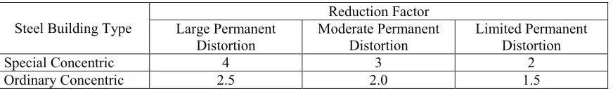
Table 1 – Inelastic Energy Absorption Factors for Steel Braced Structures
Steel Building Type
Reduction Factor Large Permanent
Distortion
Moderate Permanent Distortion
Limited Permanent Distortion
Special Concentric 4 3 2
Ordinary Concentric 2.5 2.0 1.5
For instance, for a Special Concentrically Braced Frame (SCBF) with an allowance for Moderate Permanent deformation (LS-B from Table 5-1 of ASCE 43-05) the allowable reduction factor is 3. However, if accounting for this reduction the braces are designed to have a large margin, this could result in the structure not developing the expected ductility of 3 associated with the reduction factor. For instance, a utilisation of 0.4 for the braces in tension would imply that under the DBE, they will reach a ductility of 0.4 x 3 = 1.2. Therefore, when the foundation loads are calculated, the reduced ductility needs to be taken into account. This is, the foundations should not be designed based on a structural analysis with a response spectrum reduced by a factor of 3. Instead, the foundation forces need to be calculated accounting for the maximum load that the vertical braces can transmit to the bases when they are fully utilised, i.e. at their yield point. This will also guarantee that for BDBE the foundations will be capable of carrying the maximum loads transferred by the structure.
An efficient design should aim for getting most benefit from the energy absorption introduced when the main load-carrying members behave in a ductile manner. For instance, in the case of concentrically braced frames, the bracing elements should be designed to reach their maximum allowable ductility level, i.e. by selecting the smallest section possible. This implies a decrease in the overall stiffness and frequency of the structure, which in most cases results in a reduction in the seismic load attracted by it.
The following section will look at an example of a design of a braced frame by both using the commonly used elastic method and then compared with a design considering it as a Concentrically Braced Frame optimised to minimise structural and foundation seismic forces.
METHODOLOGY
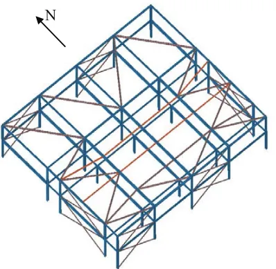
For the purpose of this study, a conventional 2 storey steel cross braced structure (See Figure 1) is analysed using both a conventional elastic response and a response considering the benefits from ductility.
Description of Case Considered
Figure 1 – Isometric View on Braced Structure Analysed
The seismic input considers the Principia Mechanic Limited (PML) response spectrum for a medium site with a 0.25g horizontal peak ground acceleration (pga), which is commonly used in the UK for seismic hazard levels with a probability of occurrence with a return period of 1 in 10,000 years. For the vertical seismic input, 2/3 of the horizontal input is adopted as common practice. As per ASCE 4-98 and ASCE 43-05, the damping levels assigned to the response spectrum depend on the level of stress experienced by the structural members that are fundamental to the lateral load path.
For instance, a structure designed to perform in a ductile manner (with permanent deformation) will experience higher levels of damping than a structure designed to perform elastically. Higher damping results in further reduction of the seismic demand.
Structure Designed to Respond Elastically
This case considers the structure shown in Figure 1responding within the elastic range when subject to both DBE and BDBE. This case represents the common historical UK design approach, which aimed to maintain an elastic structural response even for the BDBE scenario, which was frequenctly quantified in the UK as a 40% increase from the DBE scenario.
Given that the structure is designed to respond within the elastic range, the level of damping assigned to the response spectrum is only 4%, in line with Response Level 1 in ASCE 43-05 for a bolted structure.
The cross vertical braces are designed to respond in tension only as it is typical of elastic design. Designing the vertical bracing to be adequate in compression would result in excessively robust members.
For this case, the vertical braces required to withstand the seismic demand are 193.7x10 CHS (Cross area = 57.7cm2) and 273x12.5 CHS (Cross area = 102cm2) for the North-South and East-West bays respectively, steel grade S275.
Ductile Analysis
This case considers the structure shown in Figure 1 responding as a Special Concentrically Braced Frame (SCBF) in line with the associated requirements set in AISC 341-10. The typical characteristics of SCBF structures are taken into account such as:
! Capacity of member in compression is added to the overall capacity of the vertical braced bay;
! Vertical braces both in tension and compression are allowed to exceed their elastic capacities;
! The braces are selected such that the members in compression resist no less than 30% of the overall horizontal demand;
! Limitations on slenderness and local buckling are set on the bracing members such as to maintain their adequate performance following a reversal of load;
! The columns that form part of the vertical braced bays are designed to withstand the forces induced by the braces at their ultimate state. This is to prevent a brittle failure mechanism or cliff-edge effect, where the columns may buckle in compression prior to yielding of the vertical braces.
For this example, it is considered that the performance requirement allows the structure to have large permanent deformations, but should not collapse. In line with ASCE/SEI 43-05, a ductility of 4 is permitted. However, in order to provide additional margin to the BDBE scenario, the ductility in this example is limited to 3 at the DBE level. It is noted that this assumption is conservative, as the regulator’s expectations is that to address the BDBE scenario, the structure only needs to demonstrate ultimate ductile response beyond DBE.
For the structural analysis, the elastic PML spectrum was used both horizontally and vertically, with utilisations of the braced bay acting in compression and tension kept within the limit of 3.0 required by the ductility level.
For this case, the vertical braces required to withstand the seismic demand are 114.3x5 CHS (Cross area = 17.2cm2) for both the North-South and East-West bays, with a steel grade S275. These bracing members also satisfy the requirements set by AISC regarding slenderness and local buckling.
The level of damping applied to the response spectrum is 7% in line with ASCE/SEI 43-05, considering that the vertical braces (which are the members that provide ductility to the structural response) are stressed to a level beyond their elastic capacities. A damping level of 7% represents an approximate reduction of 23% in the seismic demand when compared to a 4% damping used in the elastic design.
It is noted that in order to ensure that the braces can respond as expected for a SCBF, their end connections need to be designed with special requirements as those specified in ANSI/AISC 341-10. These requirements are set, for instance, to permit the member to rotate as it buckles in compression, without inducing excessive additional bending stresses that could cause brittle failure of the connection.
RESULTS
The summary of the results for the two cases considered are shown in Table 3 below.
Table 2 – Summary of Main Results for Design Cases Considered
Case Main Mode
Natural Frequency
Maximum Elastic Stress Demand in Vertical Braces
Ultimate Base Shear
Displacements
Elastic Design 4.4Hz (E-W)
4.0Hz (N-S) 72% (DBE) 100% (BDBE) 4,758kN (E-W) 4,740kN (N-S) 12mm (E-W) 14mm (N-S)
Ductile Design 3.3Hz (E-W)
2.3 Hz (N-S)
250%
(DBE and BDBE)
1,770kN (E-W)
2,206kN (N-S)
24mm (E-W)
37mm (N-S)
The values presented in Table 3 for ultimate base shears are associated with the following:
! For the elastic case, the ultimate base shear is calculated as that obtained from the structural model for the DBE seismic scenario, with an additional 40% to account for the BDBE scenario.
! For the ductile case, the ultimate base shear corresponds to the maximum force that can be transferred by the structure to the foundation, including an overstrength factor of 1.25 to allow for the expected material strength.
From Table 3 it can be seen that when incorporating ductility in the design, the bracing members are not required to be as strong, which results in a reduced overall lateral stiffness of the structure. This has a direct impact on the associated spectral accelerations, which for the example considered, results in a decrease in the seismic demand when compared to the elastic case.
For the ductile case, the ultimate base shear (i.e. lateral demand on the foundations) is reduced by a maximum of 70% in the East-West direction, based on the elastic case. In the North-South direction, the base shear has a reduction of 63% when compared to the elastic case. This large reduction in ultimate base shears is associated mainly to the fact that the bracing members in the ductile case require a much lower cross sectional area. This governs the ultimate axial load that can be transferred by the braces onto the foundations. Other parameters that contribute to the decrease in seismic demand are:
! Reduction in the applied response spectrum acceleration due to the decrease in stiffness and associated natural frequency of the structure;
! Structural damping induced by the larger stresses in the vertical braces, which perform beyond the elastic range, thus resulting in higher absorption of energy.
It is noted that for simplification of the design cases considered, it was assumed that the foundation soil was rigid enough such that SSI effects would not occur. However, in practice, depending on the lack of rigidity of the soil, opting for an excessively rigid structure because an elastic design approach had been adopted, could result in SSI effects that would induce further amplification of the seismic demand.
Other considerations on Ductile vs Elastic Design
Similarly, the maximum lateral forces induced in the foundations at a BDBE scenario larger than 40% the DBE are not calculated. Hence, a cliff-edge effect caused by brittle failure of the foundation prior to failure of the structure is not guaranteed to be avoided for a large BDBE scenario.
For the ductile design, the ultimate failure mechanism is guaranteed by:
! Designing the columns to withstand the maximum forces that the vertical braces can ever transmit to them, accounting for material overstrength and an additional reserve margin. This ensures that a cliff-edge mechanism, where the columns buckle prior to tensile yielding of the braces, will not occur on a scenario with a large exceedance of the DBE.
! Selecting brace elements that are not excessively slender and have adequate local buckling capacity to withstand the reversal of loads natural to the seismic event, after yielding in tension and buckling in compression.
! Designing the connections of the vertical braces such that they are robust to carry the forces transferred by the braces but flexible enough to allow the rotation of the member when it buckles in compression.
CONCLUSION
A study has been completed to evaluate the differences between adopting an elastic design and a ductile design of a braced steel frame. The elastic design corresponds to the UK commonly used approach to address DBE and BDBE seismic events. The ductile design corresponds to a more refined approach that accounts for a degree of permanent deformation in the structure allowed by the performance requirement for SCBF structures, which may permit the structure to perform beyond its elastic range even for the DBE seismic event.
The main conclusions of the study are summarised below:
! Opting for a ductile design results in reductions of the overall lateral seismic demand in the structure of up to 70% when compared to the elastic design. This large reduction of seismic demand is caused mainly by the fact that smaller vertical bracing members can be used in the ductile design. The stresses in the braces are permitted to exceed their elastic limits by factors of up to 4, consistent with the ductility ratios allowed for this type of structures, although a value of only 3 was adopted in the example.
! The design adopting an elastic approach results in excessive stiffness of the structure. The large stiffness of the structure is more likely to introduce SSI effects, which in turn could result in a further increase of the seismic demand.
! The substantial lateral seismic demand for the elastic design approach could result in a complicated and costly design of the foundation system.
! Allowing for ductile performance of the members that form part of the main lateral load path of the structure (in line with all the recommendations set by standards such as AISC 341), address the current regulator’s expectations regarding performance to events beyond DBE. The ultimate failure mechanism of the structure is controlled such as to ensure that no cliff-edge effects occur even at events that exceed the DBE event by a considerable margin.
super-structure as well as the costs of design and construction of the foundations would generally outweigh any design costs.
NOMENCLATURE
BDBE Beyond Design Basis Event CHS Circular Hollow Section DBE Design Basis Event pga Peak Ground Acceleration ONR Office for Nuclear Regulation PML Principia Mechanica Ltd
SCBF Special Concentrically Braced Frame
REFERENCES
American Institute of Steel Construction, (2010). “Seismic Provisions for Structural Steel Buildings”, AISC Standard ANSI/AISC 341-10, USA.
American Society of Civil Engineers, Structural Engineering Institute, (2010). “Minimum Design Loads for Buildings and Other Structures”, ASCE Standard ASCE/SEI 7-10, USA.
American Society of Civil Engineers, Structural Engineering Institute, (2005). “Seismic Design Criteria for Structures, Systems and Components in Nuclear Facilities”, ASCE Standard ASCE/SEI 43-05, USA.
American Society of Civil Engineers, (1998). “Seismic Analysis of Safety Related Nuclear and Commentary”, ASCE Standard ASCE 4-98, USA.
American Society of Civil Engineers, Structural Engineering Institute, (2005). “Seismic Design Criteria for Structures, Systems, and Components in Nuclear Facilities”, ASCE Standard ASCE/SEI 43-05, USA.