Pressurised Shell Intersections with Local Area Wall Thinning
T. Ahmad, M. A. Khan and D. Redekop
Department of Mechanical Engineering, University of Ottawa, Ottawa, Canada
ABSTRACT
In this paper results are presented from a three-dimensional finite element stress and collapse analysis of two pressurised shell intersections having local area wall thinning. The two intersections are respectively a sphere-nozzle intersection and a cylinder-nozzle intersection (tee joint). For the first intersection thinning is considered to occur in the nozzle only, while for the second thinning is considered to occur in both shells. Various degrees of wall thinning are considered for both intersections. Comparisons are made of the stress concentration factor and the collapse pressure for intersections, without and with thinning. The results presented provide information useful for the study of the fatigue and failure characteristics of shell intersections with local area wall thinning.
INTRODUCTION
The sphere-nozzle and cylinder-nozzle (tee) intersections (Figs. 1-2) are used in the pressure vessel and piping systems of chemical plants, refineries and power generation plants. Some specific examples of these intersections are nozzles in pressure vessel heads, reactor vessels, and liquid storage tanks. Since the 1960s extensive research has been carried out to determine the linear and non-linear behavior of undamaged intersections under pressure loading. Recently, interest has turned to the determination of the characteristics of such structures damaged by wall thinning. With the rise in computer capability, the linear as well as non-linear analysis of complicated geometries such as damaged intersections can now be carried out.
Fig. 1 Cross-section sphere-nozzle intersection Fig. 2 Cylinder-nozzle (tee) intersection
There is an extensive literature dealing with stress concentration and collapse of shell structures. Mackerle [1] has published a survey of the research work on structural mechanics of pressure vessels and piping. Recent studies on thinning and its structural effect on vessels include that of Netto [2]. There have been a number of numerical studies [3-5] on pipes and vessels with local wall thinning areas (LTA). Several studies have dealt with thinning in piping elbows [3-4], while another has dealt with a thinned shell intersection [5]. Many analytical studies have dealt with the SCF in sphere-nozzle and tee joints, including the works of Dekker and Brink [6] and Xue et al. [7]. The analytical work has application though only to thin shells. Many finite element studies have been conducted on sphere-nozzle intersections [8-10], as well as on tee joints [11-13]. While finite element studies can give good results they require a lot of computational effort, and therefore simple formulas have been developed to predict the elastic stress and plastic collapse characteristics of sphere-nozzle intersections [14-16] and tee joints [17-20]. In the various studies it has been pointed out that for undamaged intersections the weakest position and failure source is the intersection region, and that the diameter and thickness ratios are the primary parameters in characterizing the structural behavior.
In this study, linear and non-linear finite element analysis (FEA) based on 3-D solid elements is performed to predict the stress concentration factor (SCF) and the plastic collapse pressure (Pc) in undamaged and damaged intersections (Figs. 1-4).
varying depth of thinning. A parametric study is finally conducted of intersections both in the undamaged and thinned states, covering a broad range of diameter and thickness ratios.
FINITE ELEMENT ANALYSIS
The commercial finite element package ADINA [21] was used in the numerical analysis of this study. For the linear stress concentration problem the equation to be solved is given by
KU=R (1)
where K is the system stiffness matrix, U is the vector of nodal displacements, and R is the vector of applied forces. For the nonlinear plastic collapse problem the equation to be solved is
0
=
−
+∆ ∆+ t
R
t tF
t(2)
where t+ tR is the vector of externally applied nodal loads at time step t+ t, while t+ tF is the force vector equivalent (in the virtual work sense) to the element stresses at time t+ t. The nonlinearity arises from the material properties and the kinematic assumptions. The algorithm used to solve the nonlinear equation is the full Newton iteration method, which
comprises of the following basic steps
( )−1 ( ) +∆ +∆ ( )−1
∆
+ t i
∆
i=
t t−
t t it
K
U
R
F
(3)
( )i t t ( )i ( )i t
t
U
U
U
=
+∆ −+
∆
∆
+ 1
(4)
where t+ tK(i-1) is the tangent stiffness matrix based on the solution calculated at the end of iteration (i-1) at time t+ t, t+ tR is
the externally applied load vector at time t + t; t+ tF(i-1) is the consistent nodal force vector corresponding to the element stresses due to the displacement vector t+ tU(i-1); and U(i) is the incremental displacement vector in iteration (i).
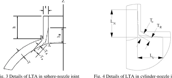
Fig. 3 Details of LTA in sphere-nozzle joint Fig. 4 Details of LTA in cylinder-nozzle joint
Plastic-multilinear material models available in ADINA are based on the von-Mises yield condition, an associated flow rule, and an isotropic or kinematic hardening rule. In the current work for the sphere-nozzle intersection the Young’s modulus was taken as 200 GPa, the Poisson’s ratio 0.26, the yield stress 289 MPa, and the ultimate strength 487 MPa. For the tee joint the Young's modulus was taken as 203.4 GPa, the Poisson's ratio as 0.3, the yield stress 241 MPa, and the ultimate strength as 413.7 MPa. For the nonlinear elastic-plastic collapse analysis the internal pressure was increased from zero in a number of discrete steps. The increase was continued until the numerical solution process became unstable. The collapse pressure was taken as the mean of the pressure at the last stable point and the collapse point.
APPROXIMATE FORMULAS FOR UNDAMAGED MODELS
To provide some control on the current numerical work predicting the SCF and collapse pressure for intersections reference was made to various simple formulas that have been developed in previous studies. The SCF is defined as the ratio of the maximum stress to the nominal stress. For internal pressure loading the nominal stress is calculated as n= PD/(2T),
where P is the internal pressure, T is the thickness of the vessel, and D is the mean diameter. The maximum stress is herein taken as the largest equivalent stress (von Mises stress), but it has been taken elsewhere also as the largest normal stress, or the Tresca stress.
For the undamaged sphere-nozzle intersection a formula due to Leckie and Penny [14] is available to predict the SCF. The formula is based on a linear shell analysis, and values for the SCF are available in chart form (Gill [15]) as a function of the parameter =(r/R)/(R/T)0.5, where r, R represent the mean radius of the nozzle and sphere, and T is the thickness of the sphere. An approximate formula for the burst (plastic collapse) pressure for an undamaged sphere-nozzle intersection has been given by Kitching et al. [16] as
Pb = 2 (T/R) u p* (5)
where T, R are again the thickness and mean radius of the sphere, u is the ultimate tensile strength, and p* is the normalized
limit pressure. A chart giving the value of p* is available in the monograph by Gill [15] (Fig. 3.37).
For the tee joint Moffat et al. [17] have derived a formula for the effective stress factor (ESF) based on a parametric analysis of tees using FEA. This factor is taken as equivalent to the SCF. The formula for the ESF is given by
EFS = [a1 + a2 (d/D) + a3 (d/D)2 + a4 (d/D)3] + [a5 + a6 (d/D) + a7 (d/D)2 + a8 (d/D)3] (t/T) + [ a9 + a10 (d/D) + a11 (d/D)2 + a12
(d/D)3] (D/T)p + [a13 + a14 (d/D) + a15 (d/D)2 + a16 (d/D)3] (t/T) (d/T)p (6)
where p = 1.2, and the constants a1 - a16 are given by; 2.5, 2.715, 8.125, -6.877, -0.5, -1.193, -5.416, 5.2, 0.0, 0.078, -0.195,
0.11, 0.0, -0.043, 0.152, -0.097. Based on empirical work Rodabaugh et al. [19-20] presented a formula for calculating the limit pressure PL for vessels with t/T 1 as
PL = P* Py
where 152 228 228 128 155 210 228 162 2 2 2 * + + + + + + = ζ ζ ζ D d D d T t T t P D T Py y
σ 2 = , T D D d =
ζ (7)
In this formula Py is the load at the onset of yield, and y is the yield stress of the material. A similar formula was given by
Antaki [18], who also presented a formula for the burst pressure Pb, based on the experimental and analytical work by
Rodabaugh [19-20], as
( )
=D T P
Pb 1.067 2σu
669 . 0 *
(8)
RESULTS
Calculations were first carried out for nine undamaged sphere-nozzle geometries as described in Table 1, and for nine undamaged tee geometries as described in Table 2. The geometric symbols of the tables are illustrated in Figs. 1-2. Calculations were secondly carried out for the same nine sphere-nozzle geometries but now with LTA as shown in Fig. 3, and for the same nine tee geometries but now with LTA as shown in Fig. 4. The LTA in the sphere-nozzle intersection (Fig. 3) was assumed to occur only in the nozzle, and to extend completely around the intersection. The wall thickness after thinning was denoted by Td, and the tapered axial length by hd. The LTA in the tee joint (Fig. 4) was assumed to occur in both the
vessel and nozzle, but its extent was restricted to an angle of 45o about the axis of the vessel. The reduced wall thickness after thinning was denoted by TR, and the tapered axial length in the nozzle and vessel by LN and LV, respectively.
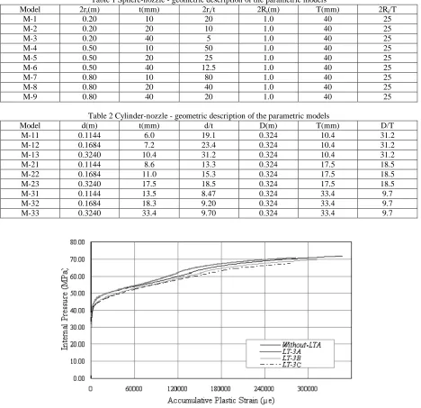
Table 1 Sphere-nozzle - geometric description of the parametric models
Model 2ri(m) t(mm) 2ri/t 2Ri(m) T(mm) 2Ri/T
M-1 0.20 10 20 1.0 40 25 M-2 0.20 20 10 1.0 40 25 M-3 0.20 40 5 1.0 40 25 M-4 0.50 10 50 1.0 40 25 M-5 0.50 20 25 1.0 40 25 M-6 0.50 40 12.5 1.0 40 25 M-7 0.80 10 80 1.0 40 25 M-8 0.80 20 40 1.0 40 25 M-9 0.80 40 20 1.0 40 25
Table 2 Cylinder-nozzle - geometric description of the parametric models
Model d(m) t(mm) d/t D(m) T(mm) D/T M-11 0.1144 6.0 19.1 0.324 10.4 31.2 M-12 0.1684 7.2 23.4 0.324 10.4 31.2 M-13 0.3240 10.4 31.2 0.324 10.4 31.2 M-21 0.1144 8.6 13.3 0.324 17.5 18.5 M-22 0.1684 11.0 15.3 0.324 17.5 18.5 M-23 0.3240 17.5 18.5 0.324 17.5 18.5 M-31 0.1144 13.5 8.47 0.324 33.4 9.7 M-32 0.1684 18.3 9.20 0.324 33.4 9.7 M-33 0.3240 33.4 9.70 0.324 33.4 9.7
Fig. 5 Comparison of pressure strain curves for sphere- nozzle model M3 with various cases of LTA
For the sphere-nozzle analysis, three different cases of LTA were considered for the model M3; case A: Td=0.75, case B:
Td=0.67, and case C: Td=0.50. The axial length hd of the thinning for the three cases was taken respectively as 0.25h, 0.67h,
and 0.5h, where h was the nozzle length. The corresponding models with local thinning were referred to as LT-3A, LT-3B, LT-3C respectively. For the other sphere-nozzle models one case of LTA only was considered, namely case C.
For the tee analysis, three cases of LTA were considered for the model M-22; case A: TR=0.75, case B: TR=0.67, case C:
TR=0.50. The axial lengths of thinning were taken as LN=5t, LV=5T. For the other tee models one case of LTA only was
considered, namely case B.
0.00 5.00 10.00 15.00 20.00 25.00 30.00 35.00
0 25000 50000 75000 100000 125000 150000
Accumulative Plastic Strain ( )
In
ter
n
al
P
res
su
re
(
M
P
a)
Without LTA [M22] Tr = 3/4 T [LT-22A] Tr = 2/3 T [LT-22B] Tr = 1/2 T [LT-22C]
Fig. 6 Comparison of load-strain curves for cylinder-nozzle model M22 with various degress of LTA
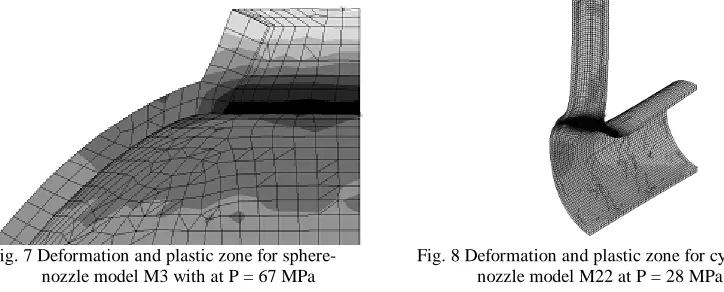
A comparison of the pressure-strain curves for the sphere-nozzle model M3 and its corresponding LTA cases is shown in Fig. 5. It is seen that the curves for the undamaged model (without-LTA) and damaged models are quite close. A similar comparison for the tee model M22 and its corresponding LTA cases is shown in Fig. 6. Here, there is a much larger difference between the four curves. In comparing the two figures it is seen that the LTA causes a much greater effect in the cylinder-nozzle intersection. This follows intuition, as in the sphere-nozzle intersection the LTA is taken only in the nozzle. Plots for the deformation and the plastic zone for the sphere-nozzle model M3 and for the tee model M-22 are shown respectively in Figs. 7 and 8.
Fig. 7 Deformation and plastic zone for sphere- Fig. 8 Deformation and plastic zone for cylinder- nozzle model M3 with at P = 67 MPa nozzle model M22 at P = 28 MPa
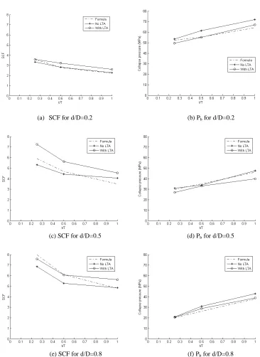
(a) SCF for d/D=0.2 (b) Pb for d/D=0.2
(c) SCF for d/D=0.5 (d) Pb for d/D=0.5
(e) SCF for d/D=0.8 (f) Pb for d/D=0.8
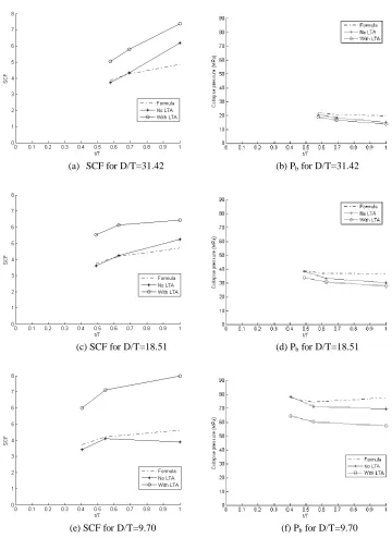
(a) SCF for D/T=31.42 (b) Pb for D/T=31.42
(c) SCF for D/T=18.51 (d) Pb for D/T=18.51
(e) SCF for D/T=9.70 (f) Pb for D/T=9.70
Fig. 10 Variation of SCF and collapse pressure for cylinder-nozzle intersection
The variation of the SCF and collapse pressure with the geometric parameters t/T and D/T for the undamaged and damaged tee joints is shown in Fig. 10. Shown also in the figure are values from the approximate formula for SCF by Moffat et al. [16], and for the collapse load by Antaki [17]. Again relatively close agreement is observed between the undamaged intersection results and the formula values. The models with LTA invariably have a larger SCF than those without LTA, and a smaller collapse load.
CONCLUSIONS
Quantitative information has been provided for the stress concentration and collapse load of pressurised shell intersections without and with local area wall thinning. Experimental results were not available for comparison. In future work it is intended to determine the effect of further mesh modification on the numerical results, to find results for other types of local area wall thinning, and to determine the fatigue characteristics of intersections under cyclical loading.
REFERENCES
1. Mackerle, J., "Finite Elements in the Analysis of Pressure Vessels and Piping, Addendum: A Bibliography (2001-2004)," Int. J. Press. Ves. & Piping, Vol. 82, 2005, pp. 571-592.
2. Netto, T.A., Ferraz, U.S., Estefen, S.F., "The Effect of Corrosion Defects on the Burst Pressure of Pipelines," J. Const. Steel Res., Vol. 61, 2005, pp. 1185-1204.
3. Zhang, L., Wang, Y., Chen, J., Cengdian, L., "Evaluation of Local Thinned Pressurized Elbows," Int. J. Press. Ves. & Piping, Vol. 78, 2001, pp. 697-70.
4. Balan, C., Redekop, D., "The Effect of Bi-directional Loading on Fatigue Assessment of Pressurized Piping Elbows with Local Thinned Areas," Int. J. Press. Ves. & Piping, Vol. 82, 2005, pp. 235-242.
5. Guillot, M.W., Helms, J.E., "Analysis of a Hemispherical Head with Nozzle and Local Thin Area," ASME PVP-Vol. 480, 2004, pp. 173-175.
6. Dekker, C.J., Brink, H.J., "Nozzles on Spheres with Outward Weld Area under Internal Pressure Analysed by FEM and Thin Shell Theory," Int. J. Press. Ves. & Piping, Vol. 77, 2000, pp. 399-415.
7. Xue, M.D., Chen, W., Hwang, K.C., "Stresses at the Intersection of Two Cylindrical Shells," Nucl. Eng. Des., Vol. 154, 1995, pp. 231-238.
8. Weisz,E., Rudolph, J., "Finite Element Analyses of the Fatigue Strength of Nozzle-to-Spherical Shell Intersections," Int. J. Press. Ves. & Piping, Vol. 64, 1995, pp. 101-109.
9. Schindler, S., Zeman, J.L., "Stress Concentration Ractors of Nozzle–Sphere Connections," Int. J. Press. Ves. & Piping, Vol. 80, 2003, pp. 87-95.
10. Rudland, D., Wilkowski, G., Wang, Y.Y., and Norris, W., "Development of Circumferential Through-wall Crack K-solutions for Control Rod Drive Mechanism Nozzles," Int. J. Press. Ves. & Piping, Vol. 81, 2004, pp. 961-971. 11. Moini, H., Mitchell, T.P., "Stress Analysis of a Thick-walled Pressure Vessel Nozzle Junction," Int. J. Press. Ves. &
Piping, Vol. 46, pp. 67-74.
12. Sang, Z.F., Xue, L.P., Lin, Y.J., Widera, G.E.O., "Limit and Burst pressure for a Cylinder Shell Intersection with Intermediate Diameter Ratio," Int. J. Press. Ves. & Piping, Vol. 79, 2002, pp. 341-349.
13. Diamantoudis, A.T., Kermanidis, T., "Design by Analysis Versus Design by Formula of High Strength Steel Pressure Vessels: A Comparative Study," Int. J. Press. Ves. & Piping, Vol. 82, 2005, pp. 43-50.
14. Leckie, F.A., Penny, R.K., "Stress Concentration Ractors for the Stresses at Nozzle Intersections in Pressure Vessels," Welding Research Council, Bulletin No. 90, 1963.
15. Gill, S.S., "The Stress Analysis of Pressure Vessels and Pressure Vessel Components," Pergamon Press, Oxford, 1970.
16. Kitching, R., Lim, C.C., Robinson, M., "Experimental Limit and Burst Pressures for Spherical Shells with Defects Adjacent to Nozzles," Int. J. Mech. Sci., Vol. 46, 1991, pp. 167-194.
17. Moffat, D.G., Mistry, J., Moore, S.E., "Effective Stress Factor Correlation Equations for Piping Branch Junction under Internal Pressure Loading," J. Press. Ves. Techn., Vol. 121, 1999, pp. 121-126.
18. Antaki, G.A., "Pipeline and Pipeline Engineering – Design, Construction, Maintenance, Integrity, and Repair," Marcel Dekker, New York, USA, 2003.
19. Rodabaugh, E.C., "A Review of the Area Replacement Rules for Pipe Connections in Pressure Vessles and Piping," Welding Resarch Council Bulletin 335, 1998, Pressure Vessel Research Council, N.Y.
20. Rodabaugh, E.C., Cloud, R.L., "Assessment of the Plastic Strength of Pressure Vessel Nozzles," J. Eng. for Ind., 1968.
21. ADINA, "AUI 8.2 – User Interface Primer and AUI Command Reference Manual," ADINA R & D Inc, Watertown, MA, 2003.
22. Khan, M.A. "Stress and Collapse Analysis of a Sphere-Nozzle Intersection with Locally Thinned Area Using Finite Elements," M. Eng. Thesis, U. of Ottawa, 2006.