ISSN(Online): 2319-8753 ISSN (Print): 2347-6710
I
nternational
J
ournal of
I
nnovative
R
esearch in
S
cience,
E
ngineering and
T
echnology
(A High Impact Factor & UGC Approved Journal) Website: www.ijirset.com
Vol. 6, Issue 8, August 2017
A Study on Outrigger System in Seismic
Response of Tall Structures by Non-Linear
Analysis
Errol Dsouza1, Dileep Kumar U2
P.G. Student, Department of Civil Engineering, Sahyadri College of Engineering, Mangalore, Karnataka, India1
Associate Professor, Department of Civil Engineering, Sahyadri College of Engineering, Mangalore, Karnataka, India2
ABSTRACT: In modern days’ structures are built very high and the structure have become slenderer. To resist the lateral force acting on structure such as the seismic or wind the structure has to be made resistant. The design of tall rise building has to be taken utmost care because it provides shelter to large number of occupants. Due to the invention of wonder materials like concrete and steel it is possible to achieve the desired lateral resisting system. One among the various methods to resist the lateral force is the Outrigger system. This project involves study of various configuration of outrigger system for G+44 storied building. Outrigger with belt truss and without have also been studied. Linear time history analysis has been adopted and data of El-Centro earthquake is used as an input. The different parameters considered are the storey displacement, storey shear, storey drift and time history plot of base force vs time. The loads considered are as per IS codes. The modeling and analysis was done using ETABS 2015. By the application of outrigger system in high rise building the seismic responses can be reduced to a greater extent.
KEYWORDS: Time-History, Outrigger system, Earthquake, Belt truss.
I. INTRODUCTION
Once the people of Babel found how to make bricks and hence the race to reach the sky started by building tall structures called as sky scrapers. The invent of concrete in construction industry has revolutionised the world. Tall buildings are the need of mega cities. There is no proper explanation for tall buildings, a building more than ten storeys is considered to be a tall building. However, there is no limitation on the height of building for tall buildings in IS codes, except the shear wall has to eliminated when the building falls under seismic zone 4 and 5. An earthquake is a hysteria of ground motion caused due to rapid discharge of energy within the earths layer. This energy is from the tectonic process that was developed because of the interaction between the earth crust and the inner part. The strain energy which is stored inside the earth is exploded in the form of sound, heat and rest of it as seismic waves. Usually an earthquake is followed by aftershocks. During a seismic activity the structure which is brittle usually undergoes a large amount of structural damage when compared to ductile designed RCC structure. The buildings now are slenderer, vertical irregular, plan irregular and hence it is more important to choose a proper lateral resisting force system. There are many lateral resisting force systems out of which this project includes a system called outrigger system.
ISSN(Online): 2319-8753 ISSN (Print): 2347-6710
I
nternational
J
ournal of
I
nnovative
R
esearch in
S
cience,
E
ngineering and
T
echnology
(A High Impact Factor & UGC Approved Journal) Website: www.ijirset.com
Vol. 6, Issue 8, August 2017
The core can either be supported by only one side or both sides. Belt truss or concrete panels supported along the periphery gives more of stiffness to the structure and acts as single unit.
II. RELATEDWORK
Hi Sun Choi, et.al, (2012) [ ]have given guidelines on design of outrigger system in building. The design has been not being available in any codes nor proper guidelines for design of this system. In this paper the Council of Tall Buildings and Urban Habitat (CTBUH) have done lot of construction work on outrigger system and its design have published design guidelines. Various benefits associated with outrigger system has been discussed. After the design process the challenge’s faced during construction has been brought to notice.The concept of floor diaphragm in virtual and conventional outrigger system and its behaviour has been explained. Using an outrigger also reduces the functionality of the building and this has to be taken into considerations. Shortening effect on the outriggers, the load path transfer on outriggers has been discussed elaborately. Different core materials used and its impact on the building in reducing the deformation and the construction sequence of the outriggers plays a very important in the stability of the building. A lot of research and practical consideration has to been known by the engineer to adopt these techniques in the building.
Thejaswini RM and Rashmi, (2015) [ ]In their research they have considered a G+14 and a particular type of irregularity in the plan of building. They have adopted various type of lateral load resisting structural systems such as rigid frame structure, shear wall, core wall structure, outrigger system etc. The analysis software used for the study was ETABS. The models were analysed for response spectrum and wind load. Since seismic analysis was involved various parameters such as displacement, storey drift, torsional irregularity was found. The results showed L shaped shear wall at the corners of irregular plan and outrigger system at specified location would reduce the drift and torsional irregularity.
Pratheek N. Biradar, et.al, (2015) [ ]they studied G+40 storeyed building and used time history data of Bhuj earthquake for analysis. The software used was ETABS and a particular regular plan was considered for the study. The location of outrigger was kept at different levels of the building and analysed for every shift in position of outrigger the displacement of building was tabulated and the reduction percentage was also calculated. In the analysis parameters such displacement, storey drift, base shear, variation of forces along with time period for linear and dynamic analysis was considered. Results showed that there was 15% reduction in displacement when outriggers were used. Building with belt truss showed an additional 6.4% reduction in displacement. The paper concludes by saying when the outrigger was placed at 20th and 26th the reduction displacement was 30%.
Syed Rizwan Nasir, et.al, (2016) [ ]studied on outrigger system as lateral resisting force system in tall buildings.The study showed various parameters like displacement, storey shear, drift and fundamental time periods. Depth of the outrigger and belt truss was restricted to one storey. Concrete outrigger responded well in case earthquake loading by reducing the deformation to a great extent. In case of wind load steel outriggers performed well in reducing the torsion of the structure. Outriggers were found to be very effective in reducing the wind effect on the building.
ISSN(Online): 2319-8753 ISSN (Print): 2347-6710
I
nternational
J
ournal of
I
nnovative
R
esearch in
S
cience,
E
ngineering and
T
echnology
(A High Impact Factor & UGC Approved Journal) Website: www.ijirset.com
Vol. 6, Issue 8, August 2017
III.OBJECTIVES
1. To study the response of the structure when the structure has incorporated the outrigger system under seismic loading.
2. To study various parameters related to the response of structure for different configuration of outriggers. 3. To compare the difference between steel and concrete outrigger systems.
4. To study the behaviour of structure when the outrigger system is provided with peripheral outrigger or belt truss.
IV.METHODOLOGY
In this present project, a G+45 storey RCC structure is taken which incorporates the outrigger beam and analysed for gravity as well lateral loads. During the analysis various IS codes have been adopted such as IS:456 for concrete design, IS:875 for loads, IS:800 for steel design, IS:1893-2002 for seismic design. The seismic effect on the structure has been studied using time history data of El Centro earthquake and corresponding various parameters has been tabulated. The main seismic parameters that are compared are Storey displacement, Storey drift, Storey shear, Time history plots of base force vs time. The following various parameters were considered for modelling and Analysis of the structure in ETABS.
A. Building Plan and its Geometry
Table 1: Building Plan and Its Geometry
Plan dimensions
Number of storeys
Typical Storey height
Bottom storey height
Total height of building
Number of bay in
X direction
Bay width in
X direction
Number of bay in
Y direction
Bay width in
Y direction
20m x 20m 45 3.1m 3.1m 139.5m 5 4m 5 4m
B. Various type of structural model considered for this study. Model 1- Bay frame.
Model 2- Bay frame with Concrete core with steel outriggers (X braced). Model 3- Bay frame with Concrete core with steel outriggers (V braced). Model 4-. Bay frame with Concrete core with Concrete outriggers (X braced).
Model 5-. Bay frame with Concrete core with steel outriggers (X braced) and belt truss. Model 6- Bay frame with Steel braced core with steel outriggers (X braced).
Model 7- Bay frame with Concrete core with concrete outrigger (X bracings) and Belt truss.
C. Outrigger location in the Elevation of structure
Based on literature review the optimum location of outrigger was given by Bryan Stafford Smith
Outrigger at first level = 1/ (4+1) = 1/5= 0.2H
Outrigger at second level = 2/ (4+1) = 0.4H
Outrigger at third level= 3/ (4+1) = 0.6H
Outrigger at fourth level= 4/ (4+1) = 0.8H
ISSN(Online): 2319-8753 ISSN (Print): 2347-6710
I
nternational
J
ournal of
I
nnovative
R
esearch in
S
cience,
E
ngineering and
T
echnology
(A High Impact Factor & UGC Approved Journal) Website: www.ijirset.com
Vol. 6, Issue 8, August 2017
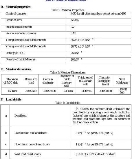
D. Material properties
Table 2: Material Properties
Grade of concrete M50 for all other members except column M60
Grade of steel Fe 345
Poison’s ratio concrete 0.2
Poison’s ratio for masonry 0.15
Young’s modulus of M50 concrete 35.35 x 10 kN/
Young’s modulus of M60 concrete 38.72 x 10 kN/
Density of RCC 25 kN/
Density of brick Masonry 20 kN/
E. Member dimensions
Table 3: Member Dimensions
Thickness of RCC slab
Beam size (mm)
Column size(mm)
Thickness of brick masonry
wall
Thickness of RCC shear
wall
Concrete Outriggers
(mm)
Steel Outriggers
150mm 300X600 500X1000 230mm 400mm 300X1000 ISMB 500
F. Load details
Table 4: Load details
a Dead load
In ETABS the software itself calculates the dead loads by applying a self-weight multiplier factor of one which is taken by the structure and the rest load cases are kept zero. Its defined in the load cases section.
b Live load on roof and floors 3 kN/ As per IS:875 (part -2)
c Floor finish on roof and floors 1 kN/ As per IS:875 (part -2)
ISSN(Online): 2319-8753 ISSN (Print): 2347-6710
I
nternational
J
ournal of
I
nnovative
R
esearch in
S
cience,
E
ngineering and
T
echnology
(A High Impact Factor & UGC Approved Journal) Website: www.ijirset.com
Vol. 6, Issue 8, August 2017
G. Seismic data
Table 5: Seismic data
Zone factor Importance factor Response reduction
factor Soil type
Zone 5 (0.36) 1.5 important office
building 5 SMRF Soil type 3
For this research time history analysis has been carried out. The ground motion data of the El- Cento earthquake has been taken as the input data.
V. RESULTSANDDISCUSSION
The results are obtained from the Time history analysis of El-Centro, for all the seven model have been compared. The parameters such as storey displacement, storey drift, storey shear and Time history plots base force vs time. The results of the analysis and the parameters associated with every model are plotted on graph and compared accordingly.
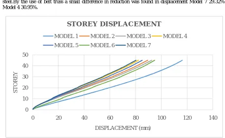
1. Storey Displacement:Structure having concrete core and concrete outrigger X shaped controls displacement by 29.3% than that of bay frame. The X bracing system reduces displacement by 23.12% and V bracing system reduces by 20%. The difference between the Model 2 and 3 is marginal.From Model 6 and 2 the displacement reduction was found to be 18.48% and 23.2% which says concrete core provides higher stiffness than that of steel.By the use of belt truss a small difference in reduction was found in displacement Model 7 29.32% and Model 4 30.95%.
Fig 1: Storey displacement
0 10 20 30 40 50
0 20 40 60 80 100 120 140
S
T
O
R
E
Y
DISPLACEMENT (mm)
S TO R E Y D IS P L A C E M E N T
MODEL 1 MODEL 2 MODEL 3 MODEL 4
ISSN(Online): 2319-8753 ISSN (Print): 2347-6710
I
nternational
J
ournal of
I
nnovative
R
esearch in
S
cience,
E
ngineering and
T
echnology
(A High Impact Factor & UGC Approved Journal) Website: www.ijirset.com
Vol. 6, Issue 8, August 2017
Table 6: Displacement observation Sl.
No
Model description Max
Displacement (mm)
Reduction in
displacement (%)
1 Bay frame 116.3 0
2 Concrete core +Steel outrigger (X) 89.5 23.12 3 Concrete core +Steel outrigger (V) 92.5 20.46 4 Concrete core +concrete outrigger (X) 82.2 29.32
5 Concrete core +Steel outrigger (X)+ Belt truss 85.1 26.82
6 Steel braced core +Steel outrigger (X) 94.8 18.48
7 Concrete core +concrete outrigger (X)+ Belt truss 80.3 30.95
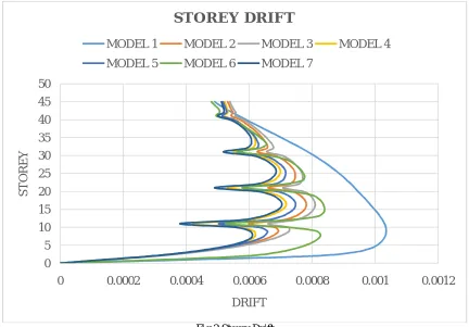
2. Storey Drift:In bay frame Model 1 the maximum drift was in storey 9 which is found to be 0.001035. In rest of the model the storey drift has reduced considerably by 20% to 30%. The drift was minimum at storey 16 for rest of the models except Model 1. This due to the outrigger which is located at storey 10.The least drift was seen model 7 were the drift was reduced by 32%.
Fig 2 Storey Drift
0 5 10 15 20 25 30 35 40 45 50
0 0.0002 0.0004 0.0006 0.0008 0.001 0.0012
S
T
O
R
E
Y
DRIFT
S TO R E Y D R IF T
MODEL 1 MODEL 2 MODEL 3 MODEL 4
ISSN(Online): 2319-8753 ISSN (Print): 2347-6710
I
nternational
J
ournal of
I
nnovative
R
esearch in
S
cience,
E
ngineering and
T
echnology
(A High Impact Factor & UGC Approved Journal) Website: www.ijirset.com
Vol. 6, Issue 8, August 2017
Table 7: Storey Drift observation Sl.
No
Model description Max Drift
Storey
1 Bay frame 0.001035 9
2 Concrete core +Steel outrigger (X) 0.000781 16
3 Concrete core +Steel outrigger (V) 0.000809 16
4 Concrete core +concrete outrigger (X) 0.000716 16
5 Concrete core +Steel outrigger (X)+ Belt truss 0.000747 16
6 Steel braced core +Steel outrigger (X) 0.000837 16 7 Concrete core +concrete outrigger (X)+ Belt truss 0.000703 16
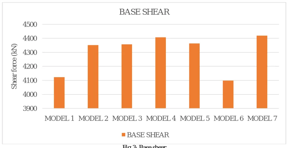
3. Base shear:The maximum base shear was found in model 7 which is 4419 kN.The minimum base shear was found in model 6 which is 4099 kN.Models with belt truss showed minimal changes as seen in model 5 is 4363kN and model 7 is 4419 kN.
Fig 3: Base shear
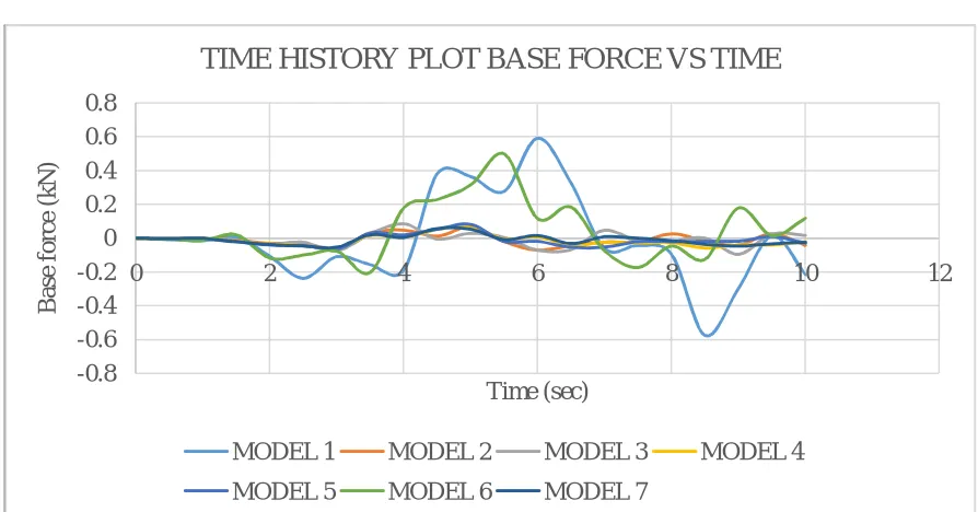
4. Time History Plots of Base force v/s Time:It can be observed from the graph 5.31 that Model 1 shows higher variation and followed by Model 6. The rest of the model shows relatively lesser variation. The models having concrete core and concrete outriggers shows less variation than compared to that of steel
3900 4000 4100 4200 4300 4400 4500
MODEL 1 MODEL 2 MODEL 3 MODEL 4 MODEL 5 MODEL 6 MODEL 7
S
h
ea
r
fo
rc
e
(k
N
)
BASE SHEAR
ISSN(Online): 2319-8753 ISSN (Print): 2347-6710
I
nternational
J
ournal of
I
nnovative
R
esearch in
S
cience,
E
ngineering and
T
echnology
(A High Impact Factor & UGC Approved Journal) Website: www.ijirset.com
Vol. 6, Issue 8, August 2017
Fig 4: Time History Plots of Base force v/s Time
VI. CONCLUSION
By studying a G+44 structure which has outrigger system and by using linear time history method for analysis certain results are obtained. Analysing these results certain conclusion is listed below.
The outriggers which are X shaped braced showed lesser displacement when compared to that V shaped braced outriggers.
The concrete outriggers showed lesser displacement when compared to that of steel outriggers. But the difference was marginal. Steel outrigger could be used as light weight material instead of concrete.
Model with concrete core performed very well when compared to that fully braced steel core. This mainly due to stiffness offered by the concrete core to that of steel.
When the outriggers were also provided with belt truss along the periphery, the structure performed very well and the displacement was found to be minimum amongst all other model.
The drift of the structure was reduced up to 30% when provided with outrigger system.
When steel material was used in the structure either for core or outriggers the base shear was reduced. As a result, in model 6 were the core and bracing was steel the base shear was found to be minimum. The weight of the structure was reduced and hence the base shear.
Time history analysis gives values considering the real time conditions, this method reduces the chances of failure in structures.
From the time history plot base force vs time the model with lesser stiffness showed higher variation.
REFERENCES
[1] Hi Sun Choi and Leonard Joseph, “Outrigger system design consideration”, International Journal of High Rise Building, Vol.1, pp.3-12, 2012. [2] Thejaswini RM and Rashmi AR, “Analysis and Comparison of Different Lateral Load Resisting Structural Forms”, International Journal of
Engineering Research & Technology (IJERT), Issue No 7, Vol.4, pp.19-23, 2015.
[3] Prateek N. Biradar and Mallikarjun s. Bhandiwad, “A Performance Based Study On Static and Dynamic Behaviour of Outrigger Structural
-0.8 -0.6 -0.4 -0.2 0 0.2 0.4 0.6 0.8
0 2 4 6 8 10 12
B
a
se
f
o
rc
e
(k
N
)
Time (sec)
TIME HISTORY PLOT BASE FORCE VS TIME
MODEL 1 MODEL 2 MODEL 3 MODEL 4
ISSN(Online): 2319-8753 ISSN (Print): 2347-6710
I
nternational
J
ournal of
I
nnovative
R
esearch in
S
cience,
E
ngineering and
T
echnology
(A High Impact Factor & UGC Approved Journal) Website: www.ijirset.com
Vol. 6, Issue 8, August 2017
[5] Goman W. M. Ho, “The Evolution of Outrigger System in Tall Buildings”, International Journal of High-Rise Buildings, Issue No 1, Vol.5, pp.14-21, 2016.