Study of Outrigger Systems for High Rise
Buildings
Sreelekshmi. S 1, Shilpa Sara Kurian2
P.G. Student, Department of Civil Engineering, SNGCE, Kadayiruppu, Ernakulam, India1
Assistant Professor, Department of Civil Engineering, SNGCE Kadayiruppu, Ernakulam, India2
ABSTRACT: Today in modern tall buildings, lateral loads induced by both wind and earthquake were battled by an arrangement of coupled shear walls. When building height increases, the structure should have a lateral load resisting systems other than shear walls for avoiding the effect of these loads, since the shear walls when used alone are suitable only upto 20 stories high. Outrigger systems are one such prominent system and are considered to be the most popular and efficient because they are easier to build and provide good lateral stiffness. This paper presents the results of an investigation on displacement, drift and base shear reduction in steel building frame with rigid outriggers, through time history analysis using the software ETABS 2015. Results shows that double outrigger system can effectively reduce seismic response of the building and optimum location of outriggers was found to be 0.75 times its height along with cap truss.
KEYWORDS: Base shear, Displacement, Drift,Outriggers, Time history analysis etc.
I.INTRODUCTION
Today’s increased need for housing in metropolitan cities leads to the emergence of high rise buildings. Tall buildings are becoming more and more slender and this leads to more possible sway during the occurrence of lateral loads. When building height increases tremendously, the structure should have lateral load resisting system other than shear walls for avoiding the effect of these loads, since the shear walls when used alone are suitable only upto 20 stories high. Outrigger systems are one such prominent system and are now considered to be the most popular and efficient because they are easier to build, save on costs and provide good lateral stiffness. Outrigger braced structures is an efficient structural form in which the central core is connected to the outer columns. The structural concept of these systems is that when the central core tries to tilt, its rotation at the outrigger level induces a tension-compression couple in the outer columns acting in opposition to that movement. Most importantly, outrigger braced structures can strengthen a building without disturbing its aesthetic appearance and this is a significant advantage over other lateral load resisting systems.
II. RELATED WORK
The purpose of this paper is to study the performance of outrigger systems during their service life. Several researches were conducted on this topic in the previous years but few of them are reviewed as follows.
conducted detailed study about outrigger systems and came to know that the use of outriggers and belt truss systems in high rise buildings increases the stiffness and makes the structural form efficient under lateral load. KiranKamath, N.Divya and AshaRao [5] (2012) had studied the static and dynamic behavior of outrigger structural systems and an investigation has been performed to examine the behavior of various alternative 3D models using ETABS software for reinforced concrete structure with central core wall with outrigger and without outrigger by varying relative flexural rigidity from 0.25 to 2.0 with step of 0.25. The optimum position is at mid height for both static and dynamic behavior for the structure considered.J.C.D. Hoenderkamp , M.C.M Bakker and H.H.Snijder [6] (2003) had presented a paper regarding a graphical method to optimize the position of outriggers on shear walls with flexible foundations.This method requires the calculation of six structural parameters. It is concluded that all these parameters need to be included in the preliminary analysis of a proposed tall building structure.Kian and Siahaan [7] (2002) has studied effectiveness of belt truss and outrigger in concrete high rise building. They have shown that deflections can be controlled effectively by the efficient use of this arrangement.R.Shankar Nair [8] (1998) conducted a detailed study of various types of outriggers and their relative behavior and performance subjected to lateral loading. It is clear from this example that belt trusses used as virtual outriggers are effective at coupling exterior columns to the core of a tall building.
III.FINITEELEMENTMODELLINGANDANALYSIS
The model considered for the present study is 120m high rise steel building frame and it represents a 40 storied building. Modelling and analysis were conducted by using the engineering software ETABS Nonlinear version 2015. The floors and roofs were modelled as rigid diaphragms. Wind loads and earthquake loads were given as per IS 875 (Part 3) and IS 1893-2002 (Part 1) respectively. Live loads were also assigned. Table 1 gives the details of the building.
Table 1: Details of the building
Particulars Steel Structure
No. of stories 40
Total height of the building 120m
Height of each story 3m
Size of beam Story 1-10 ISMB 550
Story 11-20 ISMB 450
Story 21-30 ISMB 350
Story 31-40 ISMB 250
Size of column Story 1-10 ISMB 600
Story 11-20 ISMB 500
Story 21-30 ISMB 400
Story 31-40 ISMB 300
Location Delhi
Seismic zone IV
Seismic intensity Severe
Seismic zone factor ( Z ) 0.24
Basic wind speed (m/s) 47
Importance factor ( I ) 1.0
Grade of concrete M25
Grade of reinforcing steel Fe415
Density of concrete 25kN/m2
Supports at base Fixed
Diaphragm Rigid
Here in this study, different arrangements of shear wall were considered and a best arrangement is determined by using time history analysis. In that arrangement, outriggers were provided in the structure at top, one fourth, three fourth and mid height. Cap trusses were provided in all these cases. Time history analysis was conducted to investigate the variations in displacement, drift and base shear thus the optimum position was determined. Fig.1 shows the different shear wall arrangements which were used in the study.
a) Shear wall 1(SW1) b) Shear wall 2 (SW2)
From the analysis, by taking displacement as the parameter, the third arrangement shows the least value compared to others. Hence, for further studies, the third arrangement was chosen.
Table 2: Displacement Shear wall
arrangement
Displacement (mm)
SW1 735.3
SW2 740
SW3 638.7
SW4 705.1
Since the displacement value for the selected shear wall arrangement was found to be 638.7mm, it is beyond the limiting value so the structure should have another lateral load resisting system such as outriggers. Fig.2 shows the different outrigger arrangements which were used in the study.
IV.RESULTSANDDISCUSSIONS
By conducting the time history analysis in different arrangements of outriggers, the following results were obtained.
Displacement
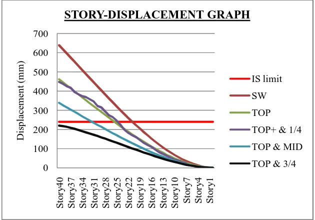
It is the deviation of the whole structure from its neutral position under an applied load. Fig 5 shows the comparison of story displacement.
Fig 5: Comparison of story displacement
While evaluating the story displacement graphs from time history analysis
,
a notable reduction was observed by the introduction of double outriggers. It can be seen that by providing outriggers at top and 3/4th height, the displacement value will be in acceptable limits. In all other cases, the displacement was beyond the limiting value.The table shows the percentagereduction of displacement from time history analysis.
Table 2: Percentage reduction of displacement
Position Displacement-
Maximumvalue (mm)
Percentage reduction (%) Bare frame with shear
wall
638.7
-Cap truss 460.9 27.83%
Out @ top &1/4th H 447.5 29.93%
Out @ top & 1/2th H 338.7 46.97%
Out @ top & 3/4th H 220.4 65.49%
0 100 200 300 400 500 600 700 S to ry 40 S to ry 37 S to ry 34 S to ry 31 S to ry 28 S to ry 25 S to ry 22 S to ry 19 S to ry 16 S to ry 13 S to ry 10 S to ry 7 S to ry 4 S to ry 1 D is pl a ce m en t (m m )
STORY-DISPLACEMENT GRAPH
IS limit SW TOPTOP+ & 1/4
TOP & MID
From the above results, it is clear that when the outriggers are provided at top and 3/4th height, the displacement value satisfies the limiting value specified in IS 1893-2002, i.e.; 0.002 times the building height and there will be a percentage reduction of about 65.49.
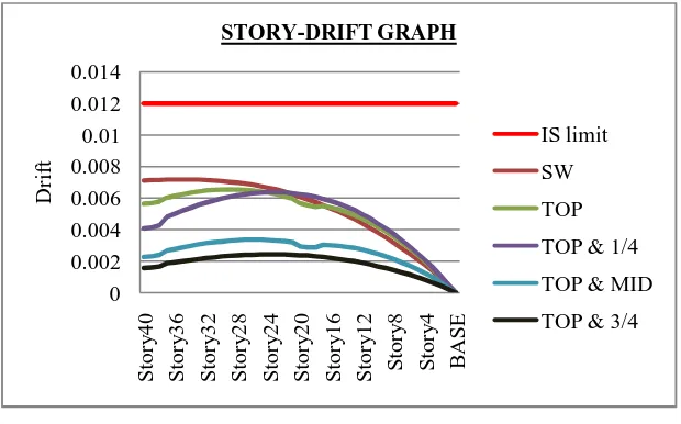
Story drift
It is the lateral drift of a level relative to the level below in a multi-story structure. Fig 6 shows the comparison of story drift graphs of bare frame with shear wall and different arrangements of outriggers from time history analysis.
Fig 6: Comparison of story drift
From the analysis, when double outriggers are used, a significant reduction can be seen in the case of story drift.
The table shows the percentagereduction of drift from time history analysis.
Table 3: Percentage reduction of drift
Position Drift- Maximum
value
Percentage reduction (%) Bare frame with shear
wall
0.0071
-Cap truss 0.0056 21.12%
Out @ top &1/4th H 0.0040 43.66%
Out @ top & 1/2th H 0.0022 69.01%
Out @ top & 3/4th H 0.0015 78.87%
When outriggers are provided at top and 1/4th height of the building, there will be a percentage reduction of about 43.66% and at top and mid height it is about 69.01%. It is to be noted that when outriggers are provided at top and 3/4th height, the percentage reduction will be 78.87%.
0 0.002 0.004 0.006 0.008 0.01 0.012 0.014 S to ry 40 S to ry 36 S to ry 32 S to ry 28 S to ry 24 S to ry 20 S to ry 16 S to ry 12 S to ry 8 S to ry 4 B A S E D ri ft STORY-DRIFT GRAPH IS limit SW TOP
TOP & 1/4
TOP & MID
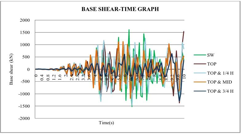
Base shear
It is an estimate of maximum expected lateral that will occur due to seismic ground motion at the base of a structure. Fig.7 shows the comparison of base shear-time graphs of bare frame with shear wall and different arrangements of outriggers from time history analysis.
Fig 7: Comparison of base shear-time graph The table shows the percentage reduction of base shear.
Table 4: Percentage reduction of base shear
Position Base shear-
Maximum value
Percentage reduction (%)
Bare frame with shear wall 1605
-Cap truss 1534 4.3%
Out @ top &1/4th H 1257 21.58%
Out @ top & 1/2th H 1117 30.31%
Out @ top & 3/4th H 626.9 60.94%
From time history analysis,the introduction of double outriggers results in about 65.49% and 78.87% displacement and drift reduction respectively. Also there is 60.94% base shear reduction. It may be noted that the obtained values are within the acceptable limits.
IV.CONCLUSION
This study assessed the overall behaviour of outrigger braced building under lateral loads from which the following conclusions can be drawn based on the above results.
Outrigger braced tall building is considered as one of the most popular and efficient tall building design because they are easier to build, save on costs, and provide massive lateral stiffness.
-2000 -1500 -1000 -500 0 500 1000 1500 2000
0
0
.4 0.8 1.2 1.6 2 2.4 2.8 3.2 3.6 4 4.4 4.8 .25 5.6 6 6.4 6.8 7.2 .67 8 8.4 8.8 9.2 9.6 10
Ba
se
s
h
ea
r
(k
N
)
Time(s)
BASE SHEAR-TIME GRAPH
SW
TOP
TOP & 1/4 H
TOP & MID
With the implementation of outrigger systems, factors such as base shear, displacement and story drift of the structure during an earthquake are lowered and hence building is to be designed only for wind and gravity loads. Hence reducing the size of structural elements, results in an economic construction.
The location of outrigger beam has a critical influence on the lateral behaviour of the structure under lateral loads and the optimum outrigger locations is found to be 0.75 times the building height along with cap truss when provided at three stories depth.
Numerical study was conducted on a 40 storied steel structure providing outriggers at top, one fourth, middle and three fourth height of the building, and outrigger at three fourth along with cap truss was found superior among the three in terms of story drift, displacement and base shear since it confirmed to the safety limits described in IS 1893-2002.
A notable reduction was observed while evaluating story displacement, drift and base shear from time history analysis
.
REFERENCES
[1] Shivacharan K, Chandrakala S, Narayana G, Karthik N M,”Analysis Of Outrigger System For Tall Vertical Irregularities Structures Subjected To Lateral Loads”, International Journal of Research in Engineering and Technology, Vol-04, Issue-05, pp. 84-88, 2015.
[2] Abdul KarimMulla and Srinivas B. N, “A Study on Outrigger System in a Tall R.C Structure with Steel Bracing”, International Journal of Engineering Research & Technology, Volume-4, Issue-7, 2015.
[3] Krunal.Z.Mistry and Prof. Dhruthi. J. Dhyani, “Optimum Outrigger Location in Outrigger Structural System for High rise building”, International Journal of Engineering Research Development, Volume-2, 2015.
[4] P.M.B. Raj KiranNanduri, B.Suresh, MD.Ihtesham, “Optimum Position of Outrigger System for High-Rise Reinforced Concrete Buildings under Wind and Earthquake Loadings”,American Journal of Engineering Research,Volume-4, issue 8, 2013.
[5] KiranKamath, N.Divya, Asha U Rao, “A study of Static and Dynamic Behaviour of Outrigger Structural systems for Tall buildings”, Bonfring International Journal of Industrial Engineering and Management Science, Volume-2, issue-4, 2012.
[6] J.C.D. Hoenderkamp , M.C.M Bakker and H.H.Snijder “ Preliminary design of high rise outrigger braced shear wall structures on flexible foundations”, Proceedings of the Second Structural Engineers World Congress, Volume -42, pp. 81-98 2003.
[7] Po SengKian, Frits TorangSiahaan, “The use of Outrigger and Belt Truss system for High-Rise Concrete Buildings”, International Journal of Engineering Development and Research, Volume-3, 2002.