Multiple ARQ Processes for MIMO Systems
Haitao Zheng
Wireless Research Laboratory, Lucent Technologies, 791 Holmdel-Keyport Road, Holmdel, NJ 07733, USA Email:[email protected]
Angel Lozano
Wireless Research Laboratory, Lucent Technologies, 791 Holmdel-Keyport Road, Holmdel, NJ 07733, USA Email:[email protected]
Mohamed Haleem
Wireless Research Laboratory, Lucent Technologies, 791 Holmdel-Keyport Road, Holmdel, NJ 07733, USA Email:[email protected]
Received 4 December 2002; Revised 19 August 2003
We propose a new automatic repeat request (ARQ) scheme for MIMO systems with multiple transmit and receive antennas. The substreams emitted from various transmit antennas encounter distinct propagation channels and thus have different error statis-tics. When per-antenna encoders are used, separating ARQ processes among the substreams results in a throughput improvement. Moreover, it facilitates the interference cancellation in certain MIMO techniques. Quantitative results from UMTS simulations demonstrate that the proposed multiple ARQ structure yields more than 30% gain in link throughput.
Keywords and phrases:MIMO systems, automatic repeat request, throughput, wireless communication, UMTS.
1. INTRODUCTION
Third-generation cellular systems are being designed to sup-port high-speed packet data services. In the downlink, which has more stringent requirements in many of such services, high-speed packet access is provided through a shared chan-nel where time-division multiplexing is used. Time slots are assigned to users at specific data rates through a scheduling algorithm based on the user data backlog and on channel
quality indication (CQI) received via a feedback channel.1
Such a transmission scheme allows multiple users to share
the system resources efficiently by adapting to traffic and
channel variations and it also avoids possible resource lim-itations that might occur if each user were allocated a ded-icated code-multiplexed channel. Therefore, it has the po-tential to improve the capacity for delay-tolerant bursty ser-vices. Examples where this scheme will be implemented in-clude the CDMA 1x EV-DO and 1x EV-DV and the UMTS
high-speed downlink packet access (HSDPA) [1,2]. Several
advanced technologies are employed in high-speed downlink transmission to improve link throughput or reduce packet delay by adapting to the time-varying channel conditions,
1Each terminal measures its channel condition and translates it into a metric to be fed back to the serving base station.
traffic statistics, and quality-of-service requirements. Some
of these adaptive techniques, relevant to this paper, are sum-marized below.
Multiple transmit and receive antennas. The use of mul-tiple antennas at each base station sector is already part of every third-generation standard. In the downlink, specifi-cally, these antennas can be used to provide transmit diver-sity and/or to direct a beam towards the intended terminal. The deployment of multiple receive antennas at data ter-minals is also being considered. The combination of mul-tiple transmit and receive antennas will enable the imple-mentation of a number of multiple-input multiple-output (MIMO) techniques that promise spectacular increases in throughput without the need for additional power or
band-width [3,4,5].
Dynamic link adaptation through adaptive modulation and coding. Typically, each transmission in the downlink shared channel is at the maximum available power, with no
power control. Therefore, link adaptation [6,7], which
ad-justs the modulation and coding schemes (MCS), provides
an efficient way of maximizing the instantaneous usage of
selects the appropriate MCS based on the CQI for the user served at each time slot. We hereby refer to the MCS selec-tion process as the mapping design.
Automatic repeat request (ARQ) or hybrid ARQ (HARQ). The performance of MCS-based link adaptation largely
de-pends on the accuracy of the CQI, which is difficult to
main-tain as velocity increases. The delay tolerance of many data services enables the use of retransmission schemes to re-cover erroneous packets. Recently, HARQ techniques have been adopted by several wireless standardization bodies, for
example, 3GPP and 3GPP2. HARQ [8,9,10] can improve
throughput performance, compensate for link adaptation
er-rors, and provide a finer granularity in the rates effectively
pushed through the channel. Upon detecting a transmission failure, mostly by cyclic redundancy check (CRC), the termi-nal sends a request to the base station for retransmission. The delay due to packet acknowledgement can be significantly re-duced by placing the HARQ functionality in the base station (Node B in UMTS) rather than in the radio network con-troller (RNC in UMTS). The packet decoder at the mobile combines the soft information of the original transmission with those of the subsequent retransmissions. The combined signal has higher probability of successful decoding. In
gen-eral, there are two ways of soft combining. Withchase
com-bining, the base station repeatedly sends the same packet and the receiver aggregates the energy from the (re)transmissions
to improve the signal-to-noise ratio (SNR) [11,12]. A more
sophisticated HARQ mechanism, namedincremental
redun-dancy (IR), transmits additional redundant information in each retransmission and gradually reduces the coding rate
until successful decoding occurs [13,14,15]. Compared with
chase combining, IR requires larger receiver buffers but it can
achieve better performance [16]. It also provides finer
gran-ularity in the encoded rates and allows for better adaptation to channel variations.
Scheduler. In a multiuser system where user channel con-ditions change over time, a scheduler can exploit those chan-nel variations by giving certain priority to the users with transitorily better channels. The scheduler critically impacts the system performance. Several scheduling algorithms have been proposed in the literature to maximize the packet data
throughput, subject to various fairness conditions [17].
The above technologies are tightly coupled. However,
since some of them reside in different layers, that is, HARQ
in the medium access control (MAC) layer and MIMO in the physical layer, they are usually discussed and treated separately. The evaluation of each technology fails to take into account the performance improvement or degradation brought about by the other one. In particular, the link layer performance of any MIMO algorithm is usually selected ac-cording to the raw data rate at some operating point, for ex-ample, 10% packet error rate. However, when some level of channel uncertainty exists and the system supports HARQ, it may be beneficial to transmit aggressively at higher packet er-ror rates and recover channel erer-rors through retransmissions
[18]. The throughput depends heavily on the transmission
strategy. An overly aggressive transmission could produce too many unsuccessful packet transmissions that diminish
the overall throughput, while an overly conservative one fails to fully utilize the channel. In this case, the overall through-put depends on the algorithms at both layers and only
cross-layer design can enable the most efficient use of the
channel.
In this paper, we address some of the key design issues as-sociated with the choice of the HARQ structure to be used for MIMO physical layer transmission. We propose a new HARQ structure that matches the layered structure of the most
pop-ular MIMO architectures [19]. Simulation results show that
the performance sensitivity to the choice of HARQ depends on the aggressiveness of the transmissions and on the type of CQI.
The paper is organized as follows. InSection 2, we
de-scribe the layered architectures with per-antenna encoding. Modifications to the conventional HARQ structure to fit
these layered architectures are discussed in Section 3. We
compare the performance of different HARQ structures in
Section 4. Conclusions are drawn inSection 5.
2. LAYERED ARCHITECTURES WITH PER-ANTENNA ENCODING
In order to approach the MIMO channel capacity in rich multipath environments, the substreams radiated from the
various transmit antennas should be uncorrelated [20,21].
Nonetheless, it may in practice be advantageous to jointly
en-code them (Figure 1a). This has motivated a blossoming
in-terest in the design of space-time (vector) codes [22]. Clearly,
when the substreams are jointly encoded, they should share a single CRC.
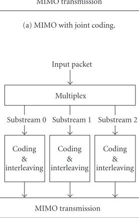
The complexity of joint detection, however, explodes as the number of transmit antennas grows large. As a result, there has also been strong interest in devising alternative approaches. One such approach is that of layered architec-tures, which incorporate multiple scalar encoders, one per transmit antenna. In these architectures, input data is de-multiplexed into multiple substreams, which are then sep-arately encoded and radiated from the various transmit
an-tennas (Figure 1b). At the receiver, the substreams are
succes-sively detected and cancelled [4,5]. Specifically, the
informa-tion extracted from each substream is reencoded, interleaved, and modulated to construct a replica of the transmitted sub-stream. This replica, properly combined with the channel re-sponse, is then subtracted from the overall received signal so that—if there are no errors—the interference contribution of this substream is removed. The complexity of these archi-tectures increases more gracefully with the number of anten-nas. Furthermore, they can capitalize on existing scalar cod-ing formats.
A layered architecture can approach the MIMO
chan-nel capacity if the data rates of the different transmit
an-tennas are appropriately adjusted [23,24]. This adjustment
MIMO transmission
Substream 0 Substream 1 Substream 2 Channel coding &
interleaving Input packet
(a) MIMO with joint coding.
MIMO transmission Substream 0 Substream 1 Substream 2
Multiplex Input packet
(b) MIMO with per-antenna coding.
Figure 1: MIMO transmitter architecture with different coding structures.
antennas at the expense of some loss in capacity [23]. To
illustrate this point,Figure 2depicts the difference between
the capacity with and without the constraint that the data rate at each of the transmit antennas be equal, for the spe-cific case of 4 transmit and 4 receive uncorrelated antennas with Rayleigh fading. For the purpose of this paper, in any event, the most relevant feature of a layered architecture is that it does not constraint the transmit antennas to be jointly encoded and share a unique CRC.
3. HARQ MECHANISMS FOR MIMO SYSTEMS
If the MAC layer is unaware of the presence of MIMO at the physical layer, HARQ simply attaches a single CRC to the packet with such CRC encompassing the data radiated from the various transmit antennas. We refer to this scheme,
depicted in Figure 3a, as MIMO single ARQ (MSARQ).
Since substreams transmitted from different antennas
en-counter distinct propagation channels, they have different
er-ror statistics. Using a typical channel propagation model with
4 transmit and 4 receive uncorrelated antennas [21], we
ob-−2 0 2 4 6 8
AverageEsN0(dB) 0
Common rate and CQI Per-antenna rate and CQI
Figure2: Ergodic Shannon capacity with 4 transmit and 4 receive antennas obtained via Monte Carlo simulation on a Rayleigh-faded channel with no antenna correlation.
serve that in more than 70% of error events,2only the
sub-streams from 1 or 2 transmit antennas are corrupted and thus
require a retransmission (Figure 4). However, upon an error
event, an MSARQ receiver has to request a retransmission of the entire packet because it relies on the single CRC over the whole packet. Retransmitting substreams that have already been correctly received wastes throughput. When multiple per-antenna encoders are used, it becomes possible to re-move the constraint that the substreams radiated from mul-tiple transmit antennas share a single ARQ process.
For per-antenna MIMO encoding architectures, we herein propose to employ multiple ARQ processes, 1 for each substream radiated from 1 transmit antenna or group of antennas. This scheme is independent of the receiver-processing algorithm and only requires that the receiver de-codes substreams independently. We refer to this scheme as
MIMO multiple ARQ (MMARQ). As shown inFigure 3b, a
CRC symbol is appended to each substream. At the receiver, each such substream is decoded and the associated CRC is used to validate the content. Multiple acknowledgment (NACK/ACK) indications are then sent back to the mitter. After receiving these acknowledgements, the trans-mitter sends fresh packets from the transmit antennas that have been successfully acknowledged and retransmits the substreams that have been negatively acknowledged through their associated transmit antennas. Hence, the HARQ
opera-tions at different transmit antennas are independent of each
other. We focus on high-speed downlink data transmission so that the overhead due to multiple CRC symbols is neg-ligible. However, we need to consider the uplink signaling overhead due to multiple acknowledgements. For each ARQ process, NACK/ACK requires an overhead of 1 bit plus error protection redundancy. Therefore, the amount of ARQ
MIMO transmission Substream 0 Substream 1 Substream 2
Multiplex Substream 0 Substream 1 Substream 2
Attach
Figure3: Transmitter structures of MSARQ and MMARQ.
−2 −1 0 1 2 3 4 5 6 7 8
AverageEsN0(dB) 0
1 substream in error 2 substreams in error 3 substreams in error 4 substreams in error
Figure4: Probability distribution of the number of corrupted sub-streams in an error event with 4 transmit and 4 receive uncorrelated antennas and frequency-flat fading.
back overhead scales with the number of transmit antennas. When that number is large, grouping the transmit antennas and assigning a single ARQ process to each group can reduce the signaling overhead.
Next, using per-antenna encoders with successive de-coding and cancellation at the receiver as an example, we
describe the receiving procedures for both MMARQ and MSARQ. The receiver decodes the transmitted substreams sequentially following a certain order, which can be opti-mized to achieve the best throughput performance. The first substream is decoded from the overall aggregate received
sig-nal Y(t). The information dataS0(t), extracted from
sub-stream 0, is then reencoded, interleaved, and modulated to construct a replica of the transmitted substream. This replica,
combined with the channel response, that is,F(S0(t),H(t)),
is then subtracted fromY(t) so that the interference
contri-bution of this substream to the others is removed. This pro-cedure is the so-called interference cancellation. The same process is then applied to the remaining substreams, which are thus successively extracted.
For MMARQ, the interference cancellation and HARQ packet combining procedures can be blended advanta-geously. In that case, the receiver would decode a substream and use its associated CRC to validate the content. If this sub-stream carries a retransmission packet and contains uncor-rectable errors, the soft symbols of the packet would be com-bined with those of the previous transmission(s) to extract the information data. The receiver would then perform in-terference cancellation to remove the inin-terference due to this substream. Interference cancellation is performed regardless of the results of the CRC validation; therefore, all the sub-sequent substreams can be decoded without waiting for the retransmission of the current substream. However, the relia-bility of the decoded data is much higher after HARQ packet combining and, thus, using such data to reconstruct the sig-nal replicas for interference cancellation reduces error
i=i+ 1 Interference cancellation
Remove contribution ofSi(t) fromY(t) based on channelH(t):Y(t)=Y(t)−F(Si(t),H(t)) NACK(i)=0 NACK(i)=1
Failed CRC(i) check OK
No HARQ packet combining
Combine soft symbols ofSi(t) with previous transmission(s) and redecodeSi(t)
Yes OK
Retransmission ? Failed CRC(i) check DecodeSi(t) fromY(t)
Yes i < M No
Feedback NACK(0· · ·M−1)
& exit
Received signalY(t),i=0
Figure5: MMARQ receiver flow chart.
In contrast, it is not so easy to combine HARQ with interference cancellation when MSARQ is employed. As
il-lustrated inFigure 6, MSARQ separates HARQ packet
com-bining from interference cancellation. The receiver performs packet decoding and interference cancellation to extract the substreams and then combines those substreams into a com-pound packet. In this case, decoding errors at each substream could propagate to the substreams that are decoded
after-wards. Such error propagation could severely degrade the performance. Another alternative would be to recancel inter-ference on the HARQ combined signal upon a CRC failure.
This procedure is shown in Figure 7, wherein interference
Feedback NACK & exit
NACK=0 NACK=1
Failed CRC check OK
No DemultiplexSi(t) (i=0· · ·M−1) intoS(t)
HARQ packet combining
Combine softSi(t) with previous transmission(s) and redecodeSi(t),i=0· · ·M−1
Yes OK
Retransmission ? Failed CRC check
DemultiplexSi(t) (i=0· · ·M−1) intoS(t) No
i < M i=i+ 1
Interference cancellation
Remove contribution ofSi(t) fromY(t) based on channelH(t):Y(t)=Y(t)−F(Si(t),H(t))
DecodeSi(t) fromY(t)
Yes Received signalY(t),i=0
Figure6: MSARQ receiver flow chart type I.
4. COMPARISON OF MSARQ AND MMARQ
In this section, we compare the performance of MSARQ and
MMARQ in the context of UMTS HSDPA [25]. The most
prominent features of HSDPA, which is specifically geared towards delay-tolerant data, are as follows.
(1) A fraction of the power and code space available at the base station is allocated to HSDPA while the rest is
as-signed to pilots, overhead channels, and voice traffic.
Feedback NACK & exit
NACK=0 NACK=1
Failed CRC check OK
NO DemultiplexSi(t) (i=0· · ·M−1) intoS(t)
HARQ packet combining Y(t)=Y0(t)
Fori=0· · ·M−1,
Combine soft symbols ofSi(t) with previous transmission(s) RedecodeSi(t)
Remove contribution ofSi(t) fromY(t) :Y(t)=Y(t)−F(Si(t),H(t)) RedecodeSi+1(t) based onY(t)
Yes OK
Retransmission ? Failed CRC check
DemultiplexSi(t) (i=0· · ·M−1) intoS(t) NO
i < M i=i+ 1
Interference cancellation
Remove contribution ofSi(t) fromY(t) based on channelH(t):Y(t)=Y(t)−F(Si(t),H(t))
DecodeSi(t) fromY(t) Yes Received signalY(t), letY0(t)=Y(t) andi=0
Figure7: MSARQ IC receiver flow chart.
frame lasts 2 milliseconds. We assume that the entire HSDPA code space (10 codes in this paper) and trans-mit power are assigned to the scheduled user. That is, the base station transmits to only one user in each frame using 10 codes and full power. The transmit sig-nal consists of a superposition of such 10 orthogosig-nal codes.
(3) The Node B (or base station) MAC determines the
transmission rate for the user being served, based on the CQI.
(4) The HARQ functionality resides between the Node B and the mobile terminal to permit soft combining and fast NACK/ACK feedback.
terminals. The Node B possesses the following functionali-ties.
(a) MACHSDPA. It performs scheduling, MCS selection,
and HARQ, based on the CQI feedback and the NACK/ACK signaling from each terminal.
(i) Scheduler. System performance depends heavily on the scheduling algorithm. For the purpose of this work, we limit ourselves to a round-robin scheduler, which exhibits maximum fairness across users. Additionally, with such scheduler, it is easy to quantify the system-level performance from the single-user performance. (ii) MCS selection. The MCS at each transmit antenna is
separately controlled through CQI feedback from the
receiver [23,24].
(iii) HARQ. The downlink HARQ operates
asyn-chronously, that is, the retransmissions can take place anytime after the Node B receives a NACK/ACK. The scheduler determines the exact time. To com-pensate for the NACK/ACK feedback delay of 2 frames, each HARQ entity operates in terms of three stop-and-wait (SAW) processes. This allows HARQ to operate continuously without waiting for a NACK/ACK signal. For MSARQ, all transmit antennas use a single HARQ entity with 3 processes while, for MMARQ, each transmit antenna uses one HARQ entity with 3 processes. Chase combining is used to combine the initial transmission with the retransmis-sions. The maximum number of retransmissions is 30. If a corrupted packet cannot be recovered after exhausting the maximum number of retransmis-sions, the packet is discarded and the associated loss should be recovered by higher layer error control mechanism.
(b)PHY. The physical layer simulation consists of a
se-quence of events such as transmission and reception of sig-nals, signal-to-interference-and-noise ratio (SINR) evalua-tion, and channel estimation. It employs a bandwidth of 5 MHz with 3.33-milliseconds frames. We assume that the uplink channel operates at a rate of 64 kbps. At the terminal, the substreams radiated by the various transmit antennas are decoded according to a fixed order. The MCS of each such substream is selected based on its detected SINR at the re-ceiver and it is then fed back as a CQI message. Some addi-tional premises are summarized below:
(i) fading is Rayleigh-distributed and frequency-flat and the channel is either perfectly known at the receiver or modeled by adding simulated estimation noise onto the actual channel;
(ii) pedestrian speed (3 Km/hr);
(iii) 70% of transmit power dedicated to HSDPA; (iv) 10 out of 16 orthogonal codes dedicated to HSDPA;
(v) 4 uncorrelated transmit and 4 uncorrelated receive an-tennas;
(vi) 7 MCSs employing turbo codes with varying rates and
symbol repetition [4]: QPSK rate 1/4 repeated 4 times,
QPSK rate 1/4 repeated 2 times, QPSK rate 1/4, QPSK
rate 1/2, QPSK rate 3/4, QAM rate 1/2, and 16-QAM rate 3/4.
The probability of each substream being detected er-roneously is given by a frame error rate (FER) versus in-stantaneous SINR curve for each MCS. For the above MCS
schemes, these curves are displayed inFigure 8.
The ultimate performance measure is the single-user throughput, defined as the ratio between the number of in-formation bits correctly received by a user and the time that the channel is allocated to that user:
throughput
= total good bits
(total frames with transmissions)·frame duration.
(1)
Notice that the throughput represents the peak net through-put that can be delivered to a user.
It should be pointed out that the throughput depends on the mapping between the detected SINR and the selected MCS per antenna. Such mapping is adjusted in order to max-imize the throughput while maintaining some target FER measured prior to HARQ operation. When this target FER is small (less than 5%), the probability of retransmission is low and there is no large gain with any kind of ARQ. As the target FER increases, the probability of retransmissions grows and there is a considerable gain with MMARQ. Hence, we opti-mize the FER to maxiopti-mize the throughput.
4.1. Performance with perfect channel estimation and feedback
Our initial simulations assume perfect channel estimation and error-free uplink feedback. We first examine the ad-vantage of combining HARQ with interference cancellation by comparing the compound packet error performance of MSARQ and MSARQ IC. Separating interference cancella-tion from HARQ combining fails to eliminate the interfer-ence from any corrupted substream even if the substream is later fully recovered through HARQ packet combining. Such
inefficiency results in a higher compound packet error rate
(Figure 9). To quantify the advantage of per-antenna HARQ in MMARQ, the throughput performances of MMARQ,
MSARQ, and MSARQ IC are compared inFigure 10. We
ob-serve that MMARQ achieves 10%–20% improvement over MSARQ IC and 26%–40% over MSARQ. Thus, the contri-butions of combined operation and multiple ARQ structures are roughly equal. The ergodic Shannon capacities for open-loop single-transmit single-receive and 4-transmit 4-receive configurations are also shown in the same figure as refer-ences.
−4 −2 0 2 4 6 8 10 12
Figure8: Frame error rate (FER) versus SINR for a single transmit and a single receive antenna.
−2 0 2 4 6 8
AverageEsN0(dB) 0
Figure9: Compound packet error rate of MSARQ and MSARQ IC.
−2 −1 0 1 2 3 4 5 6 7 8
AverageEsN0(dB) 0
Figure 10: Throughputs of MMARQ, MSARQ, and MSARQ IC with interference cancellation in ideal conditions.
corresponding individual substream error rates are 2%–5%
and 8%–18%, respectively. In practice, it is quite difficult
to guarantee a substream error rate of 5% or less. There-fore, the optimal throughput of MMARQ would be easier to achieve in a realistic environment. Nevertheless, the
op-timized throughputs are shown inFigure 11, where the
im-provement of MMARQ drops to around 10% with respect to MSARQ IC and 20% with respect to MSARQ. By oper-ating at a low packet error rate, channel coding and packet combining can eliminate most channel errors. As such, the throughput gap between MSARQ and MSARQ IC also di-minishes.
4.2. Performance with imperfect channel estimation and feedback
Next, we examine the performance of MSARQ, MSARQ IC, and MMARQ in more realistic conditions, with imperfect channel estimation and imperfect uplink feedback. The main sources of imperfection are limited pilot power, finite chan-nel coherence time, and feedback delay. We model these non-idealities by adding noise to the SINR, that is,
ˆ
γdB=γdB+N
0,σa2, (2)
where ˆγdBrepresents the SINR in dB as estimated by the
re-ceiver, γdB represents the actual SINR in dB, and N(0,σa2)
represents Gaussian noise with varianceσ2
a. The estimation
error not only impacts the MIMO signal detection and de-coding process, but also impacts the MCS selected for each transmit antenna. In addition, the uplink feedback channel also encounters a uniformly distributed binary error rate of 6%, which could corrupt the CQI and the NACK/ACK
indi-cation(s). Figure 12illustrates the throughput performance
of MMARQ, MSARQ, and MSARQ IC for σ2
a = 1.5 dB.
The performance degradations range from 10% to 18% for MMARQ, 17% to 32% for MSARQ, and 16% to 24% for MSARQ IC. Relatively, MMARQ is less sensitive to chan-nel estimation noise and feedback errors. As the level of
un-certainty increases, it becomes more difficult to guarantee a
successful transmission without sacrificing packet through-put. In this case, it is beneficial to transmit aggressively and use HARQ to recover from channel errors. Overall, MMARQ achieves 30%–45% throughput improvement over MSARQ, while per-antenna ARQ contributes to a 15%–25% through-put improvement.
5. CONCLUSION
We have proposed a new ARQ scheme suitable for any
MIMO scheme in which substreams radiated from diff
−2 −1 0 1 2 3 4 5 6 7 8 AverageEsN0(dB)
0
Figure 11: Throughputs of MMARQ, MSARQ, and MSARQ IC with interference cancellation in ideal conditions using the opti-mized MCS/SINR settings.
−2 −1 0 1 2 3 4 5 6 7 8
AverageEsN0(dB) 0
Figure 12: Throughput of MMARQ, MSARQ, and MSARQ IC with interference cancellation in realistic conditions (with imper-fect channel estimation and imperimper-fect uplink feedback).
channel estimation and error-free uplink feedback, where MMARQ improves the throughput by 25%–40%. We then performed the simulations in more realistic conditions, with imperfect channel estimation and possibly erroneous uplink feedback. Such uncertainty leads to a higher loss rate, and
HARQ becomes a major technique for efficient error
con-trol and recovery. Hence, MMARQ is even more favorable with the performance improvement increasing to 30%–45% compared with MSARQ. It should be pointed out that the results presented here are based on the premise of
frequency-flat fading and uncorrelated antennas. Frequency-selective fading may modify this conclusion, and this problem is cur-rently under investigation.
Traditionally, the physical layer had been considered the performance bottleneck in wireless systems due to the unpre-dictable nature of the radio channel. Higher layer issues, such as scheduling, link adaptation, retransmissions, and mobile routing, used to be discussed and treated separately from major physical layer issues. With the convergence of mobile communications and data services, however, there is a grow-ing need for a cross-layer design that facilitates the interac-tion of multiple protocol layers. In particular, one can couple the design of link layer (i.e., MAC and RLP) with that of the physical layer. The superior performance of MMARQ con-firms the benefits of such joint layer design.
REFERENCES
[1] Third Generation Partnership Project, “Physical layer aspects of UTRA high speed downlink packet access (Release 2000),” 3GPP Tech. Rep. 25.848, Technical Specification Group Radio Access Network, 2001.
[2] 3GPP2 C.S00024, “CDMA2000 high rate packet data air-interface specification,” 2000.
[3] A. Lozano, F. R. Farrokhi, and R. A. Valenzuela, “Lifting the limits on high speed wireless data access using antenna ar-rays,”IEEE Communications Magazine, vol. 39, no. 9, pp. 156– 162, 2001.
[4] G. J. Foschini, “Layered space-time architecture for wireless communication in fading environments when using multiple antennas,”Bell Labs Technical Journal, vol. 1, no. 2, pp. 41–59, 1996.
[5] G. J. Foschini, G. D. Golden, R. A. Valenzuela, and P. W. Wolniansky, “Simplified processing for high spectral effi -ciency wireless communication employing multi-element ar-rays,”IEEE Journal on Selected Areas in Communications, vol. 17, no. 11, pp. 1841–1852, 1999.
[6] K. Balachandran, S. R. Kadaba, and S. Nanda, “Channel qual-ity estimation and rate adaptation for cellular mobile radio,” IEEE Journal on Selected Areas in Communications, vol. 17, no. 7, pp. 1244–1256, 1999.
[7] B. Vucetic, “An adaptive coding scheme for time-varying channels,” IEEE Trans. Communications, vol. 39, no. 5, pp. 653–663, 1991.
[8] S. Lin, D. Costello, and M. Miller, “Automatic-repeat-request error-control schemes,”IEEE Communications Magazine, vol. 22, no. 12, pp. 5–17, 1984.
[9] D. J. Costello Jr., J. Hagenauer, H. Imai, and S. B. Wicker, “Ap-plications of error-control coding,” IEEE Transactions on In-formation Theory, vol. 44, no. 6, pp. 2531–2560, 1998. [10] Third Generation Partnership Project, “Hybrid ARQ
meth-ods for FDD in Release 2000,” TSG-R WG1 document, TS-GRl#13(00)0637, May 2000.
[11] G. Benelli, “An ARQ scheme with memory and soft error de-tectors,”IEEE Trans. Communications, vol. 33, no. 3, pp. 285– 288, 1985.
[12] D. Chase, “Code combining–a maximum-likelihood decod-ing approach for combindecod-ing an arbitrary number of noisy packets,”IEEE Trans. Communications, vol. 33, no. 5, pp. 385– 393, 1985.
[14] R. Love, B. Classon, A. Ghosh, and M. Cudak, “Incremental redundancy for evolutions of 3G CDMA systems,” inProc. IEEE 55th Vehicular Technology Conference, 2002. VTC Spring 2002, vol. 1, pp. 454–458, Birmingham, Ala, USA, May 2002. [15] A. Das, F. Khan, A. Sampath, and H. J. Su, “Performance of
hybrid ARQ for high speed downlink packet access in UMTS,” inProc. IEEE VTS 54th Vehicular Technology Conference, 2001. VTC 2001 Fall, vol. 4, pp. 2133–2137, Atlantic City, NJ, USA, 2001.
[16] P. Frenger, S. Parkvall, and E. Dahlman, “Performance com-parison of HARQ with chase combining and incremental re-dundancy for HSDPA,” inProc. IEEE VTS 54th Vehicular Tech-nology Conference, 2001. VTC 2001 Fall, vol. 3, pp. 1829–1833, Atlantic City, NJ, USA, 2001.
[17] M. Andrews, K. Kumaran, A. Ramanan, K. Stolyar, P. Whit-ing, and R. Vijayakumar, “Providing quality of service over a shared wireless link,” IEEE Communications Magazine, vol. 39, no. 2, pp. 150–154, 2001.
[18] H. Zheng and H. Viswanathan, “Optimizing the ARQ perfor-mance in downlink packet data systems with scheduling,” in Proc. IEEE VTS Vehicular Technology Conference, 2003. VTC 2003 Fall, Orlando, Fla, USA, October 2003.
[19] H. Zheng, A. Lozano, and M. Haleem, “Multiple ARQ pro-cesses for MIMO systems,” inProc. of IEEE 13th Symposium on Personal, Indoor and Mobile Radio Communication (PIMRC ’02), Lisbon, Portugal, September 2002.
[20] I. E. Telatar, “Capacity of multi-antenna Gaussian channels,” European Transactions on Telecommunications, vol. 10, no. 6, pp. 585–595, 1999.
[21] D. Chizhik, F. R. Farrokhi, J. Ling, and A. Lozano, “Effect of antenna separation on the capacity of BLAST in correlated channels,” IEEE Communications Letters, vol. 4, no. 11, pp. 337–339, 2000.
[22] V. Tarokh, N. Seshadri, and A. R. Calderbank, “Space-time codes for high data rate wireless communication: perfor-mance criterion and code construction,” IEEE Transactions on Information Theory, vol. 44, no. 2, pp. 744–765, 1998. [23] A. Lozano, “Capacity-approaching rate function for layered
multiantenna architectures,” IEEE Transactions on Wireless Communications, vol. 2, no. 4, pp. 616–620, 2003.
[24] S. T. Chung, A. Lozano, and H. C. Huang, “Approaching eigenmode BLAST channel capacity using V-BLAST with rate and power feedback,” inProc. IEEE VTS 54th Vehicular Tech-nology Conference, 2001. VTC 2001 Fall, vol. 2, pp. 915–919, Atlantic City, NJ, USA, October 2001.
[25] Third Generation Partnership Project, “UTRA high-speed downlink packet access (Release 4),” 3GPP Tech. Rep. 25.950, Technical Specification Group Radio Access Network, March 2001.
Haitao Zhengreceived her B.S. degree with highest honor in electrical engineering from Xian Jiaotong University, China, in 1995, the M.S. and Ph.D. degrees in electrical en-gineering from the University of Maryland, College Park, MD, in 1998 and 1999, respec-tively. From 1995 to 1998, she was an In-stitute for System Research Fellow at Uni-versity of Maryland. She received the 1998-1999 George Harhalakis Outstanding
Sys-tems Engineering Graduate Student Award in recognition of out-standing contributions in cross-disciplinary research from the Uni-versity of Maryland. Since August 1999, she is with Wireless Research Laboratory, Bell Labs, Lucent Technologies, Holmdel, NJ. Her research interests include wireless communications and
networking, multimedia communications, and signal processing. Recently, she received the Bell Laboratories 2002 Presidents Gold Award in recognition of outstanding level of innovation, technical excellence, and business impact. She currently serves as the TPC Member of IEEE Multimedia Signal Processing Technical Com-mittee, TPC of ICME 2003, TPC of Globecom 2003, Guest Edi-tor of the IEEE JSAC Special Issue on Advanced Mobility Manage-ment and QoS Protocols for Wireless Internet, and Guest Editor of the EURASIP Journal on Applied Signal Processing Special Issue on Cross Layer Design for Communications and Signal Process-ing. She has served as the TPC Member of ICME 2002, ICC 2003, ICASSP 2002, and so forth.
Angel Lozanowas born in Manresa, Spain, in 1968. He received his Engineer degree in telecommunications (with honors) from the Polytechnical University of Catalonia, Barcelona, Spain, in 1992 and his M.S. and Ph.D. degrees in electrical engineering from Stanford University, Stanford, Calif, in 1994 and 1998, respectively. Between 1996 and 1998, he worked for Pacific Communica-tion Sciences Inc. and for Conexant Systems
in San Diego, Calif. Since January 1999, he has been with Bell Lab-oratories, Lucent Technologies, Holmdel, NJ. Since October 1999, Dr. Lozano has served as Associate Editor for IEEE Transactions on Communications. He holds 6 patents.
Mohamed Haleem received his B.S. Eng. degree from the Department of Electrical and Electronic Engineering, University of Peradeniya, Sri Lanka in 1990, the M.Phil. degree from the Department of Electrical & Electronic Engineering, Hong Kong Univer-sity of Science & Technology, in 1995, and is currently working toward his Ph.D. degree in electrical engineering at Stevens Institute of Technology, Hoboken, NJ. He was with