R E S E A R C H
Open Access
Channel estimation for MIMO multi-relay
systems using a tensor approach
Xi Han
1*†, André LF de Almeida
2†and Zhen Yang
3†Abstract
In this paper, we address the channel estimation problem for multiple-input multiple-output (MIMO) multi-relay systems exploiting measurements collected at the destination only. Assuming that the source, relays, and destination are multiple-antenna devices and considering a three-hop amplify-and-forward (AF)-based training scheme, new channel estimation algorithms capitalizing on a tensor modeling of the end-to-end communication channel are proposed. Our approach provides the destination with the instantaneous knowledge of all the channel matrices involved in the communication. Instead of using separate estimations for each matrix, we are interested in a joint estimation approach. Two receiver algorithms are formulated to solve the joint channel estimation problem. The first one is an iterative method based on a trilinear alternating least squares (TALS) algorithm, while the second one is a closed-form solution based on a Kronecker least squares (KRLS) factorization. A useful lower-bound on the channel training length is derived from an identifiability study. We also show the proposed tensor-based approach is applicable to two-way MIMO relaying systems. Simulation results corroborate the effectiveness of the proposed estimators and provide a comparison with existing methods in terms of channel estimation accuracy and bit error rate (BER).
Keywords: Channel estimation; Cooperative MIMO; Relaying; Tensor decomposition
1 Introduction
Cooperative communications have been considered as a promising concept to improve the link performance in modern wireless communication systems due to spa-tial diversity gains, enhanced coverage, and increased capacity [1-4]. In this context, relaying has been com-monly accepted as a key technique to improve system performance by overcoming channel impairments, such as fading, shadowing, and path loss, in wireless fading channel environments [4-6]. By resorting to relay-assisted cooperation, multiple wireless links between mobile sta-tions and base stasta-tions are established to create a vir-tual multiple-input multiple-output (MIMO) system [7]. In the simplest relay processing strategy, the relay sta-tions amplify and forward the received data towards the base station. In this work, we adopt amplify-and-forward (AF) relaying due to its simplicity of implementation [5]. This strategy is preferable when fixed relay stations have
*Correspondence: [email protected] †Equal contributors
1Information Network Center, Beijing University of Posts and Telecommunications, Beijing, China
Full list of author information is available at the end of the article
a limited computation capacity as opposed to the base station.
The overall link reliability of cooperative diversity schemes strongly depends on the accuracy of channel state information (CSI) associated with the multiple hops involved in the overall communication. Moreover, the use of common precoding techniques at the source and/or relays generally requires instantaneous CSI knowledge of the different channels to optimize transmission [8,9]. In practice, however, the CSI is unknown and has to be estimated with the aid of training sequences [10,11]. For two-hop relaying systems, the associated channel matri-ces can be estimated in separate LS estimation stages that operate sequentially at the destination [10]. When the communication involves additional hops, such a sequen-tial LS estimation approach still applies by using addi-tional transmission phases. The main problem is that channel estimation errors accumulate across the consec-utive stages. In [11], a closed-form solution was pro-posed for the joint estimation of the channel matrices in a two-hop MIMO relaying system, avoiding error propagation.
A few recent works have developed efficient receiver algorithms based on tensor analysis for channel esti-mation and/or symbol detection in cooperative systems [12-16]. In [12], a training sequence-based channel esti-mation algorithm is proposed for two-way relaying sys-tems with multiple antennas at the relays. Recently [14], a channel estimation algorithm based on parallel factor (PARAFAC) model [17,18] was developed for two-hop MIMO relay systems. The approach allows estimation of the channel matrices associated with both hops by resort-ing to trainresort-ing sequences. Other few recent works have developed tensor-based receivers for one-way two-hop cooperative systems [13,15,16]. In particular, the approach of Ximenes et al. [16] assumes a Khatri-Rao space-time (KRST) coding [19] at the source node, and a semi-blind receiver is proposed by assuming the existence of a direct link between the source and the destination.
The approach of Roemer and Haardt and Rong et al. [12,14] allows a joint estimation of the channel matrices by resorting to training sequences. With the idea of avoid-ing the use of trainavoid-ing sequences at the users’ and relays’ transmissions, the work [13] proposed a blind receiver for uplink multiuser cooperative diversity systems based on a PARAFAC model for the received signal. However, [13] is limited to a clustered relaying scenario, where relays belonging to the same cluster have the same spa-tial signature. The common feature of all these works is on the assumption of only two hops (source-to-relays and relays-to-destination). To further extend the coverage area and combat channel impairments such as path-loss and shadowing, it may be advantageous to introduce an addi-tional hop along with an extra communication phase by means of three-hop relaying [5]. We highlight that the interest of the proposed work is on the joint channel estimation problem (i.e., joint channel and symbol estima-tion is not addressed here). The joint channel estimaestima-tion problem was addressed in [12] for a two-way relaying sys-tem and in [14] for a one-way two-hop syssys-tem. From a tensor modeling viewpoint, the common feature of both works is on the use of the PARAFAC model. Herein, we focus on a one-way three-hop multi-relay system, while resorting to a PARATUCK2 model to derive the proposed algorithms.
In this work, novel channel estimators are proposed for MIMO multi-relay systems. Assuming that the source, relays, and destination are multiple-antenna devices and considering a three-hop AF-based training scheme, new channel estimation algorithms capitalizing on a multi-linear structure of the end-to-end communication chan-nel are proposed. The proposed approach is based on a PARATUCK2 tensor model [20] of the data collected at the destination only, which allows the channel matrices to be jointly estimated at the destination. Two receiver algorithms are formulated to solve the channel estimation
problem. The first one is an iterative channel estima-tion method based on a trilinear alternating least squares (TALS) algorithm derived from a PARATUCK2 tensor model of the received data, while the second one is a closed-form solution based on a Kronecker least squares (KRLS) factorization. The proposed approach provides an extension of the idea recently proposed in [14] to a more general scenario with two-tier relaying using MIMO AF relays. Identifiability of the channel matrices is also examined in this work, and a useful lower-bound on the channel training length is derived. In contrast to con-ventional pilot-assisted LS channel estimation, where the channel matrices are estimated separately in consecutive stages, our proposed algorithms make a more efficient use of cooperative diversity by providing a joint estima-tion of all the channel matrices. As will be clear later, such a joint channel estimation is possible due to the use of the tensor approach to model the end-to-end system.
In comparison with conventional (multi-stage) LS chan-nel estimation [10], the proposed tensor-based estimators have two distinguishing features: i) they avoid accumu-lation of channel estimation errors since all the channel matrices are estimated simultaneously (either iteratively or in closed-form), and ii) they can operate under less restrictive (and more flexible) conditions on the required number of antennas at the relays and/or destination, as will be clear from our identifiability analysis. Our approach also includes the PARAFAC-based channel esti-mator of [14] as a particular case. We also show that the proposed tensor modeling approach copes with a two-way MIMO multi-relaying communication system, where the TALS and KRLS channel estimators can be applied.
This paper is organized as follows. In section 2, the system model and working assumptions are described. Section 3 formulates the proposed approach. The data model is recast using tensor analysis, and the two chan-nel estimation algorithms (TALS and KRLS) are derived. Identifiability of the channel matrices is also examined in this section. In section 4, we provide an extension of the proposed tensor-based signal model to a two-way MIMO relaying scenario. Numerical results are presented and discussed in section 5, and the conclusions are drawn in section 6.
Notation: Scalars are denoted by lowercase letters
CJ×R, i.e., AB = A
(:,1)⊗B(:,1),. . .,A(:,R)⊗B(:,R) ∈ CIJ×R.
2 System model
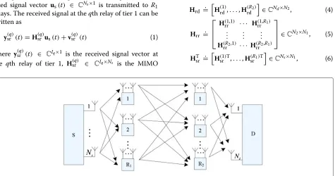
We consider a three-hop MIMO AF communication sys-tem where the source node transmits information to the destination node with the aid ofR1relays in the first tier andR2relays in the second tier. As shown in Figure 1, the source and destination nodes are equipped withNs ≥ 2 andNd ≥2 antennas, respectively, and half-duplex relays are considered. The qth relay of tier 1, which receives data from the source node, is equipped withIqantennas, q=1,. . .,R1, while thepth relay of tier 2, which receives data from tier 1 relays, is equipped withJpantennas,p= 1,. . .,R2. The total number of antennas that transmit in second and third phases are denoted byN1=I1+· · ·+IR1
andN2=J1+ · · · +JR2, respectively.
Some key assumptions are now given: (i) relays are synchronized at the symbol level. More specifically, the timing offset is assumed to be within one symbol period, so that timing information is acquired only through some form of (rough) coarse synchronization; (ii) fading is assumed to be frequency flat, and the data block size is smaller than the channel coherence time so that the chan-nel is considered as time invariant; (iii) the direct links between the source (resp. tier 1 relays) and the destination node are not availablea. This situation is evidenced in the current uplink of IEEE 802.16j.
2.1 Data model
The communication between source and destination is accomplished in three hops. In the first hop, the modu-lated signal vectorus(t) ∈ CNs×1 is transmitted to R1 relays. The received signal at theqth relay of tier 1 can be written as
y(srq)(t)=H(srq)us(t)+v(srq)(t) (1)
where y(srq)(t) ∈ CIq×1 is the received signal vector at the qth relay of tier 1, H(srq) ∈ CIq×Ns is the MIMO
channel between the source and theqth tier 1 relay, and v(srq)(t)∈CIq×1is an additive noise vector. Noise samples are modeled as independent and identically distributed complex Gaussian random variables with zero mean and unit variance.
In the second hop, the source stops transmission and all the R1 relays of tier 1 amplify their received signals with diagonal AF matricesG(1),. . .,G(R1)and
simultane-ously forward the resulting signals to the tier 2 relays. The received signal vector at thepth relay of tier 2 is then given by
y(rrp)(t+1)= R1
q=1
H(rrp,q)G(q)ysr(q)(t)+vrr(p)(t+1) (2)
whereH(rrp,q)∈CJp×Iq is the MIMO channel linking theR1 tier 1 relays toR2tier 2 relays, whilev(rrp)(t+1) ∈ CIp×1 denotes the corresponding noise vector. In the third hop, the source and all tier 1 relays are silent, while the tier 2 relays process the received signal vector with the diagonal AF matricesJ(1),. . .,J(R2)and forward their amplified
sig-nals to the destination. The received signal vector at the destination is then given by
yrd(t+2)= R2
p=1
H(rdp)J(p)y(rrp)(t+1)+vrd(t+2), (3)
whereH(rdp)∈CNd×Jpis the MIMO channel linking thepth tier 1 relay to the destination, andvrd(t+2)∈CNd×1the corresponding additive noise term.
Let us define the multi-relay (block) channel matrices
Hrd =.
H(1)rd,. . .,H(R2)
rd
∈CNd×N2, (4)
Hrr =.
⎡ ⎢ ⎣
H(1,1)rr · · · H(1,R1)
rr ..
. ... ... H(R2,1)
rr · · · H(rrR2,R1)
⎤ ⎥
⎦∈CN2×N1, (5)
HTsr =.
H(1)Tsr ,. . .,H(R1)T
sr
∈CNs×N1, (6)
and let G =. bdiagG(1),. . .,G(R1) ∈ CN1×N1 andJ =.
bdiagJ(1),. . .,J(R2)∈CN2×N2be the two diagonal
matri-ces that collect the AF coefficients of the overall multi-relay system. Using these definitions, and using (1) and (2), we can rewrite (3) as follows:
yrd(t+2)=HrdJHrrGHsrus(t)+vrd(t+2), (7)
where vrd(t+2) = vsr(t) +vrr(t+1) + vrd(t+2) is the total noise at the destination, which contains the fil-tered noise contributions from the multiple relays, with vsr(t) = HrdJHrrGvsr, vrr(t+1) = HrdJvrr(t+1),
vrr(t+1)=.
v(1)Trr (t+1),. . .,v(rrR2)T(t+1)
T
∈CN2×1,
vsr(t)=.
v(1)Tsr (t),. . .,v(srR1)T(t)
T
∈CN1×1.
Note that, since this work is concerned with channel estimation, the AF matricesGandJcannot be optimized at the transmission (source and relays). Therefore, for sim-plicity, we have assumed that these matrices are diagonal. The use of non-diagonal AF matrices in the proposed approach is left for a future work. Note also that, once the channels are estimated, the design of full AF matrices can be done, e.g., based on the SVD of the channel matri-ces, following the idea of [9] or on the mean-square error (MSE) criterion [21]. If simplified AF schemes are used, where only power allocation is done,GandJare diagonal matrices, the coefficients of which can be designed as a function of the mean channel and noise powers [5] or opti-mized from power allocation strategies, as shown recently in [22].
2.2 Conventional LS estimation method
The simplest approach to estimate the effective channel Heff = HrdJHrrGHsr (including the amplifying factors) is based on training sequences. If separate estimations of the multi-relay channelsHrd, Hrr, andHsrare required, for instance, to optimize the source precoding matrix and the relays’ AF matrices, three separate LS estima-tion stages should operate sequentially at the destinaestima-tion. The method would work similarly to that of Kong and Hua [10]. DenoteS0 ∈ CNs×L0 as the training sequence matrix sent by the source node, whileS1d ∈ CN1×L1 and S2d ∈ CN2×L2 are the training sequence matrices sent by the relays at tiers 1 and 2, respectively. Assume that orthogonal training sequences are used in all stages, which implies training sequences of lengthL0≥Ns,L1≥N1and L2≥N2at the source, tier 1 and tier 2 relays, respectively. In the first stage,S2dis transmitted from all tier 2 relays to the destination. The LS estimate of Hrd is obtained as
Hrd=Y1SH2d, (8)
where Y1 ∈ CNd×L2 is the received signal matrix at the destination during the first training stage. In the second
stage,S1dis transmitted from all tier 1 relays to the des-tination via AF processing at the tier 1 relays. Defining Y2 ∈ CNd×L1 as the data received from tier 1 relays at the second training stage, an LS estimate of Hrr can be obtained as
Hrr=HrdJ
†
Y2SH1d. (9)
Finally,S0is transmitted from the source to the destina-tion via the two tiers of relays. The destinadestina-tion collects the received data inY3 ∈ CNs×L0. An estimate ofHsris then found as
Hsr=HrdJHrrG
†
Y3SH0. (10)
This method requires 6 transmission phases to provide the destination with all the channel matrices (1 phase for estimating Hrd, 2 phases for estimating Hrr and 3 phases for estimating Hsr). Note that the channel esti-mation errors accumulate across the consecutive stages, due to the dependency between successive channel esti-mates. Moreover, this method requires Nd ≥ N2 ≥ N1 for the uniqueness of the LS estimates of Hrr and
Hsr. In the following, we adopt a different path to solve this problem by capitalizing on tensor analysis. The idea is to provide the destination with a joint estimate of all the partial channels Hrd, Hrr, and Hsr by exploit-ing the tensor structure of the end-to-end signal model. The proposed approach allows channel estimation to be performed under less restrictive conditions on the num-ber Nd of receive antennas at the destination compared with the conventional LS estimator, while avoiding error accumulation.
3 Proposed approach
In order to derive the proposed channel estimators, we first recast the formulation of the system model by resort-ing to multi-way (tensor) analysis. First, let us divide the overall training period intoK time blocks. In every time block, the same training sequence matrix S0 ∈ CNs×L0 is transmitted by the source node. In thekth time block, the relays of tiers 1 and 2 use the AF matrices Gk and
Jk, respectively,k = 1,. . .,K. Let us defineE ∈ CK×N1 andF ∈ CK×N2 as channel training matrices such that
Dk(E) =. Gk and Dk(F) =. Jk, where Dk(·)forms a diag-onal matrix out of the kth row of its matrix argument. Otherwise stated, the rows of E (resp. F) hold the AF coefficients of the R1 (resp. R2) relays associated with the different time blocks. Then, the signal received at the destination during thekth time block can be written as:
whereVk = HrdDk(F)HrrDk(E)Vsr,k+HrdDk(F)Vrr,k,
Regarding the structure of the channel training matri-cesE ∈ CK×N1 andF ∈ CK×N2, unless otherwise stated,
their columns are chosen as length-Krandom sequences following a uniform distribution between [−1, 1]. These sequences are defined beforehand and known at the des-tination node. With such a choice, the signals transmitted by the relays across theKtime blocks have random phases and are subject to limited power fluctuations. Clearly, this design is not optimal for minimizing the mean square error of the channel estimation. Determining an optimum design for these matrices is a difficult problem and is not pursued in this work. Nevertheless, extensive computer simulations have demonstrated that this choice yields very good results. For convenience, we will come back later to the problem of choosing EandF from a channel iden-tifiability viewpoint. A more elaborated design of these matrices will be then proposed.
Upon reception of the data matrix Yk, k = 1,. . .,K, an unstructured estimate of the end-to-end channel dur-ing thekth time block is first obtained at the destination. Multiplying both sides of (11) with the known training sequence matrixSH0 yields
is the matrix-of-interest that represents the effective end-to-end channel, Vk is the total noise matrix, and Hk is the noisy observation of Hk. We can assemble the set {H1,· · ·,HK} to form a three-way array, or a third-order tensor,H ∈ CNd×Ns×K, whose dimensions areN
d (first dimension), Ns (second dimension), and K (third dimension).
Equation (14) corresponds to a PARATUCK2 model of the (noiseless) tensor H [23]. The PARATUCK2 model has first appeared in [20]. A more comprehensive formu-lation is given in [23], which also details an alternating least squares procedure for estimating its matrix factors.
Here, we show that this tensor model can be exploited to derive novel channel estimators for a cooperative MIMO relaying system.
Now, let us define
H[1]=. [vec(H1),· · ·, vec(HK)]∈CNdNs×K (15)
where H[1] is a matrix ‘unfolding’ for the tensor H obtained by stacking column-wise itsKslices. Define also
Wk=Dk(F)HrrDk(E)∈CN2×N1. (16)
Substituting (14) into (15), and applying property vec(ACB)=BT⊗Avec(C), we get
row ofE(resp.F), and is the Khatri-Rao (columnwise Kronecker) product.
Applying property vecAdiag(x)B = BTAx, we get from (17) the following expression:
vec(H[1])=1vec(Hrr), (19)
In addition to the matrix unfolding H[1], it is useful to define two other matrix unfoldings, which collect the information of tensorH. Therefore, let us now define
H[2]=.
From (14) and (16), it follows that
and
3.1 Identifiability of channel matrices
Identifiability of Hsr, Hrr, and Hrd in the LS sense from H[1], H[2], and H[3] (see Equations (19), (24), and (25)), respectively, requires that 1 =
column-rank. These requirements come from the fact that 1,Z[2], andZ[3]must be left-invertible, from which the following necessary conditions are obtained:
NdNsK≥N1N2, NdK ≥N1, NsK≥N2. (27)
From the three inequalities and from the fact that we must haveK ≥ 2, the lower bound on the numberK of time blocks necessary for identifiability is given by
K≥max
wherexis equal to the smallest integer that is greater than or equal tox.
Note that the identifiability of the channel matrices Hsr, Hrr, and Hrd from the unstructured channel ten-sor H will ensure that the compound channel Hc = HrdHrrHsr ∈ CNd×Ns is strictly unique. Note also that conditions NdNsK ≥ N1N2 andNdK ≥ N1 are clearly much less restrictive in terms of the required numberNd of antennas at the destination node, in comparison with
the conventional three-step LS estimator that requires Nd≥N2≥N1. Otherwise stated, estimation of the partial channels can be done even in situations where the number of receive antennas is much less than the number of relay antennas (provided thatK satisfies condition (28)). This situation may arise in scenarios with denser deployments of relay stations, where the total number of relay anten-nas exceeds those of source and/or destination antenanten-nas. As shown by these inequalities, the possibility of afford-ing fewer receive antennas is compensated by an increase on the numberK of training blocks, which represents a trade-off.
Condition (28), although necessary, is not sufficient for identifiability. Since Z[2] =. (IK⊗Hrd)2 ∈ CNdK×N1
Otherwise,Z[2]andZ[3]will be rank-deficient, even if (28) is respected.
Let us assume that the partial channels Hsr, Hrr, and Hrd are full rank matrices, which is a reason-able assumption when the wireless links are assumed to undergo scattering-rich multipath propagation. The fol-lowing corollaries can then be obtained:
C1 IfN1=N2, identifiability of the partial channels is
guaranteed forN1≤NsandN2≤Nd;
C2 IfN1=1, identifiability of the partial channels is guaranteed forN2≤NdandN2≤K;
C3 IfN2=1, identifiability of the partial channels is
guaranteed forN1≤NsandN1≤K.
Remark: For the first corollary, we can note that ifN1≤ Ns andN2 ≤ Nd, then HTsr⊗Hrd is full column-rank, which ensures that1 ∈ CNDNsK×N2 is full column-rank due to its Khatri-Rao product structure [24]. Likewise, 2 ∈ CN2K×N1 and3 ∈ CN1k×N2 are also full column-rank in this case, guaranteeing the identifiability of the channel matrices. Regarding the second corollary, it cor-responds to a special case of our system model where the first relay tier reduces to a single-antenna relay. In this case, satisfyingN2≤NdandN2≤Kensures that1,Z[2], andZ[3] are all full column-rank, so that the three par-tial channels are identifiable. The same reasoning is valid for the third corollary, which is analogous to the second one.
3.2 Essential uniqueness
LetHsr,Hrr,Hrd
and Hrr = (2)rr Hrr(1)rr, where the following relation
Note that permutation ambiguity does not exist due to the knowledge of the training matricesEandF. The relation (29) can be obtained by replacing the alternative solutionsH¯sr, Hrd, andHrr into (14) and then applying some basic manipulations using properties of the Kro-necker product. Equation (29) turns into the following relations:rd(2)rr =αIN2andsr(1)rr =(1/α)IN1, where
α is an arbitrary scalar factor. These two relations come from the fact that the Kronecker product between any two diagonal matrices is equal to the identity matrix if and only if these diagonal matrices are (scaled) identity matri-ces that compensate each other. Consequently,Hsr,Hrr, andHrdcan be recovered in an essentially unique manner up to scaling factors. The scaling ambiguity can be elim-inated by normalizing the first column ofHsror the first row of Hrd to one. Since these ambiguities compensate each other, the compound channel is strictly unique and we haveHc=HrdHrrHsr=HrdHrrHsr=Hc.
3.3 Trilinear alternating least squares algorithm
The TALS algorithm is an iterative estimation method that alternates among the LS estimations of the chan-nel matricesHsr,Hrr, andHrd by fitting a PARATUCK2 model from the noisy matrices H[i] = H[i] +V[i], i = 1, 2, 3. Note that the noise term V[i] is constructed in a way analogous toH[i],i=1, 2, 3, following Equations (15) and (21), respectively. The AF training matricesEandF are assumed to be known at the destination and are fixed during the estimation process. From (19), (24), and (25), we respectively obtain the following linear optimization problems:
These LS estimation problems can be solved alternately by estimating one channel matrix at each time, while fix-ing the other matrices to their values obtained in previous estimation steps. Therefore, each iteration of the algo-rithm has three estimation steps. The algoalgo-rithm starts by randomly initializing two out of the three channel matri-ces and proceeds until convergence. In the following, a summary of the TALS algorithm is provided.
TALS algorithm(direct estimation ofHsr,Hrr,andHrd)
1. Setn=0;
3. Find an estimate ofHsrusing (22), by solving the LS
problem
the solution of which at the nth iteration is given by
4. Find an estimate ofHrdusing (23), by solving the LS problem
the solution of which at the nth iteration is given by
the solution of which at the nth iteration is given by
hrr(n)= model reconstruction error does not significantly change between two successive iterations.
due to the knowledge of the AF training matrices E andF.
3.4 Kronecker least squares algorithm
We now derive a closed-form solution to our channel estimation problem by exploiting the mixed Kronecker/ Khatri-Rao factorization structure of the matrix unfolding H[1]defined in (17). Starting from (13), the noisy version of (15) is given by:
Our goal is to directly identify the channel matrices from (35). However, let us first address the determin-istic design of the AF training matrices E and F such thatZZH =. ETFT ETFTH = IN1N2. Assuming
K ≥ N1N2, this condition is satisfied by designingZ, for instance, as a discrete Fourier transform (DFT) matrix. Having fixed the structure ofZ, we are left with the prob-lem of factorizing this matrix as the Khatri-Rao product betweenET andFT. This problem can easily be solved by means ofK rank-one matrix factorizations, which admit unique solutions. Note that thekth column ofZcan be written as Note that the proposed design, although not optimized to minimize the mean square error of the channel esti-mation, ensures that the noise characteristics in (33) will not be changed whenH[1] is post-multiplied byZH (i.e., inverse DFT transformation).
Coming back to the channel estimation problem, from (35), let us definexn1,n2 ∈CNsNd×1as the [(n1−1)N2+
matrix obtaining by reshaping, we have
˜
Xn1,n2 =hrr(n2,n1)Hrd(:,n2)Hsr(n1, :) (37)
Consider the singular value decomposition (SVD) of
˜ by averaging over theN1andN2independent estimates, respectively:
Note that the columns of the estimatedHsrandHrdhave unit energy while each entry of Hrr concentrates all the energy of the wireless link connecting the source node to the destination node via a given tier 1-tier 2 relay pair. Such an interpretation is useful for designing transmit and receive spatial filters for system optimization as well as for power allocation purposes.
Discussion: The KRLS algorithm involves the computa-tion ofN1N2SVDs to provide rank-one approximations for the matricesX1,1,. . .,XN1,N2, of dimensionsNd×Ns,
much lower bound onK, as discussed in Section 3.1. This is clearly a trade-off between both estimators in terms of identifiability conditions and computational complexity. As will be shown in the next section, both estimators pro-vide satisfactory performances, and the choice of the best estimator is rather dependent on the design constraints of the system. For instance, we can say that the TALS estima-tor is preferable if processing power at the receiver is not too limited, as is often the case with base station recep-tion in outdoor micro- or macro-cells. The KRLS solurecep-tion would be more likely chosen in indoor scenarios, where channel coherence time is long enough to allow for higher values ofK.
4 Extension to two-way MIMO relaying systems
In the previous sections, we have focused on a multi-relay cooperative scheme, where transmission is directed in one direction, i.e., from a specific source to a specific desti-nation via two tiers of multiple relays. In this section, we show that the same modeling approach can be extended to a two-way MIMO relaying scenario, where pilot/data transmission takes place in both directions. In the first phase, two sources simultaneously transmit their data to the multiple relays. Note that, in the two-way case, the relays of each tier receive a superposition of Ns1 +Ns2
signals coming from sources 1 and 2. In the second and third phases, inter-relay communication takes place. More specifically, in phase two, tier 1 relays transmit signals towards tier 2 relays, while tier 1 relays stay silent. In phase three, the opposite happens. Finally, in the fourth commu-nication phase, all the relays transmit to the two sources, and each one of them receives a superposition ofN1+N2 signals.
In the first transmission phase, we assume that training symbol matricesS1∈CNs1×LandS2∈CNs2×Lare
trans-mitted from sources 1 and 2, respectively. We omit the additive noise terms for convenience of presentation. The signal received at theith relay tier is given by:
X(i)=Hs1riS1+Hs2riS2=H(i)S, i=1, 2, (48) sen by source i, is designed to satisfy the following conditions:
(i) SiSHi =INi,i=1, 2,
(ii) S1SH2 =0N1×N2.
A possible construction satisfying these two conditions is based on the normalized DFT matrix of sizeL×(Ns1+
Ns2), withL ≥Ns1 +Ns2. This design allows the sources
to eliminate the self-interference generated by their own transmission, when receiving the signal back from the relays.
In the second and third phases, where inter-relay com-munications happen, the signal received at the relays of tierifrom the relays of tierj,(i,j)= {(1, 2),(2, 1)}, can be written as:
Z(ki) = HrjriDk(Ej)X(j)
= HrjriDk(Ej)H(j)S, (49) k=1,. . .,K, whereHrjri ∈CNi×Nj is the MIMO channel linking the relays of tierjat transmission to the relays of tieriat reception,(i,j) = {(1, 2),(2, 1)}. Note that chan-nel reciprocity in the inter-relay communications is not a necessary assumption which means that we may have Hr1r2 =Hr2r1.
Finally, in the fourth transmission phase, the signals received at sources 1 and 2 are post-multiplied bySH2 and SH1, respectively, to accomplish self-interference elimina-tion, yielding
signal model (14), we have the following correspondences
Consequently, the tensor-based channel estimation algorithms proposed in the previous section can be equally applied at each source to estimate the channels
¯
H(i,1), H¯(i,2) andG(rri), i = 1, 2, from Equations (50) and (51), respectively. If reciprocity is assumed in the two-way relay channels, we have: cular case, the PARATUCK2 models (50) and (51) become essentially equal, i.e., they depend on the same unknown channel matricesHs1,Hs2, andGto be estimated. Note,
however, that such a reciprocity is not a necessary assumption of our modeling approach, which can be used in the general case of non-symmetrical two-way MIMO relay channels.
5 Numerical results
We now present computer simulation results for assess-ing the performance of the proposed channel estima-tor in selected system configurations. The estimaestima-tor’s performance is evaluated in terms of the normalized mean square error (NMSE) of the estimated chan-nel matrices. From the estimated chanchan-nels, the per-formance in terms of bit error rate (BER) is calcu-lated by assuming a linear receive filter. The BER and NMSE curves are plotted as a function of the over-all signal-to-noise ratio (SNR) at the destination. This SNR is given by the ratio between the powers of the useful signal component and the noise component in Equation (11). For each simulated SNR value, the results represent an average over L = 5, 000 Monte Carlo runs. At each run, the channel coefficients are drawn from a circularly symmetric complex-valued Gaussian distribution with zero-mean and unit variance, while the transmitted symbols are drawn from a BPSK sequence. The SNR level at the tier 1 and tier 2 relays are assumed to be 30 dB above the SNR level at the destination.
For purposes of performance evaluation, the scaling ambiguities affecting the estimates of the channel matri-ces are removed by assuming the first column of Hsr and first row of Hrd contain all one elements, simi-larly to [11,14]. These scaling ambiguities can be deter-mined as follows. First, we find sr = D1HTsr
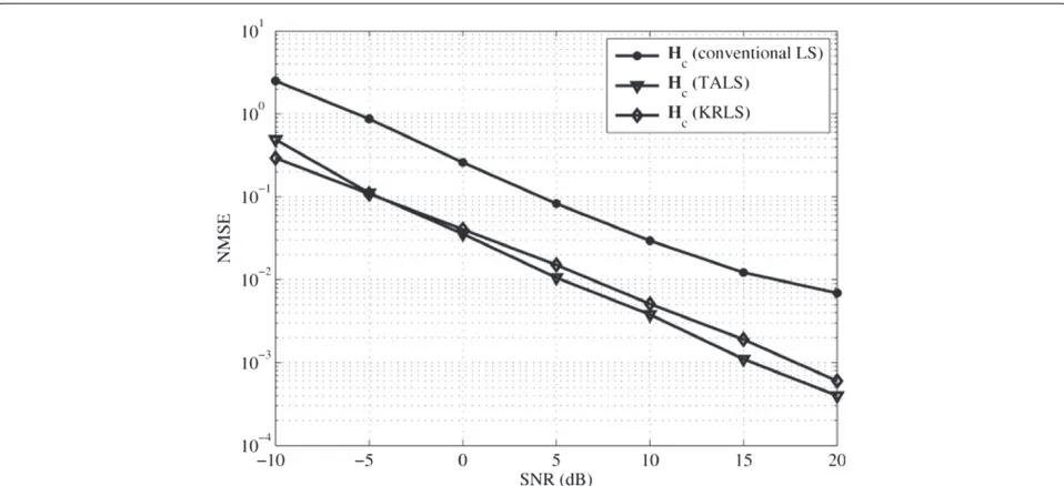
In Figure 2, we depict the NMSE performance for the compound channel of our proposed estimators in compar-ison with the conventional LS estimator. The parameters are Ns = 2, N1 = 4, N2 = 4, Nd = 6, K = 16, L0 = 30, and the number of transmitted data symbols is N = 1000. We can see that TALS and KRLS have similar performances, which are considerably better than the conventional (three-stage) LS estimator. The worst performance of the LS estimator comes from the error accumulation across successive channel estimation stages, which degrades its overall NMSE performance.
Figure 3 shows the NMSE performance of our proposed estimators in comparison with the two-hop bilinear alter-nating least squares (BALS) estimator of Rong et al. [14]. This estimator is a special case of the proposed one, where only one tier of relays is used. In this case, model (11) reduces to
Yk =HrdDk(E)HsrS0+Vk, (64) k=1,. . .,K,
and the channel matrices Hsr and Hrd are estimated by means of a BALS algorithm. The parameter setting is the same as that of Figure 2. It can be seen the proposed estimator operates satisfactorily, being able to effectively estimate the three channel matrices. Figure 3 also indicates the proposed estimator performs close to the BALS estimator operating in a two-hop system. A small performance degradation is observed, which is due to the presence of an additional AF transmis-sion phase of our three-hop system, resulting in a higher overall noise contribution at the destination. Note also that the TALS estimator involves three estimation steps while the BALS one has two estimation steps only.
Figure 2NMSE of estimated compound channelHc.Proposed estimators (TALS and KRLS) vs. conventional LS estimator.
same as those of the previous experiment. The ZF filter output is given by:
SZF=
⎡ ⎢ ⎣
HrdD1(F)HrrD1(E)Hsr ..
.
HrdDK(F)HrrDK(E)Hsr
⎤ ⎥ ⎦
†
Y. (65)
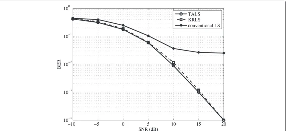
This figure shows similar BER performances for TALS and KRLS, which are better than that of the conventional LS algorithm. This result corroborates the effectiveness of
our channel estimators when used with linear receiver for symbol detection. In Figure 5, we evaluate the impact of the number of relay antennas on the BER performance of a linear ZF detector using the proposed TALS channel esti-mator. The fixed system parameters areNs =2,Nd = 6, L0 = 30, andK = 10. It can be seen that the BER per-formance is considerably improved as the number of relay antennas is increased, corroborating the expected gains of cooperative diversity. Although not plotted in this figure, the BER curves of the KRLS estimator are similar to those obtained with the TALS one.
Figure 4BER performance of linear ZF detector (TALS and KRLS).BER performance of a linear ZF detector at the destination designed from the estimated channel matrices (TALS and KRLS).
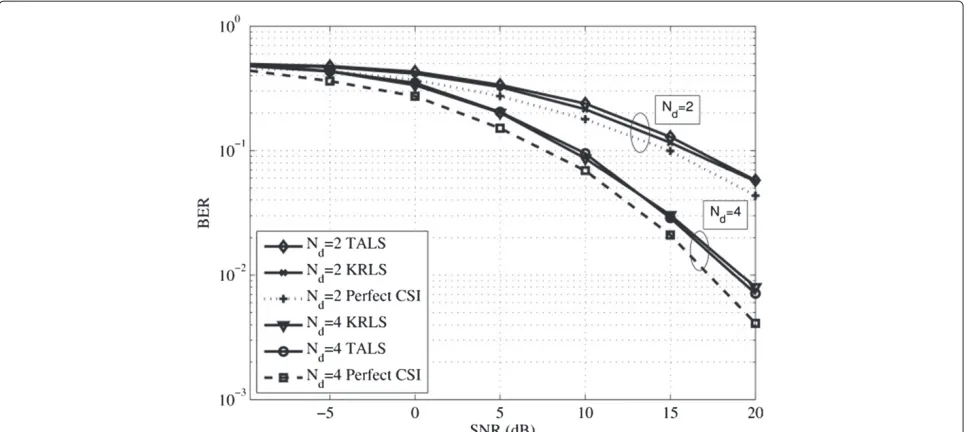
Figure 6 depicts the performance of the ZF receiver designed from the perfect CSI for all channel matrices. Two parameter settings are considered, where Nd = 2 and 4, respectively. The other system parameters are fixed to Ns = 2, N1 = N2 = 3, L0 = 6, and K = 9. First, it can be seen that the BER performances are con-siderably improved as the number of antennas at the destination is increased, owing to the higher spatial diver-sity, as expected. From these results, we also find that the
TALS and KRLS estimators provide similar results and, more interestingly, their performances are close to that of the perfect CSI case. For instance, for a target BER of 10−1, the SNR gap with respect to the perfect CSI case is less than 2 dB.
6 Conclusions
We have proposed channel estimation algorithms for MIMO AF multi-relay systems. The proposed estimators
Figure 6BER performance of linear ZF detector versus the number of antennas at the destination.BER performance of a linear ZF detector as a function of the number of antennas at the destination (TALS and KRLS).
are designed to provide the destination (base station) with the instantaneous CSI of all the channels involved in the communication. In contrast to conventional pilot-assisted channel estimation, the proposed algorithms make a more efficient use of cooperative diversity by providing a joint estimation of all the channel matrices thanks to the use of a tensor modeling of the end-to-end system. Such a joint estimation can be accomplished either iteratively (using TALS) or in closed-form (using KRLS). Our numerical results corroborate the effectiveness of the proposed algo-rithms. The TALS estimator has a higher computational complexity than the KRLS one due to its iterative nature. On the other hand, the minimum condition for operation of KRLS (K ≥ N1N2) is more restrictive than the identi-fiability conditions of TALS, which implies more training (i.e., higher number of time blocks) to carry out the joint channel estimation. Both algorithms are suitable to the joint channel estimation problem, and a particular choice is mostly dictated by practical system requirements. We have also provided an extension of the proposed approach to two-way MIMO multi-relay system and verified that such an extension results in the same tensor model as the one-way scenario. Consequently, the proposed algorithms can be applied to one- and two-way multi-relay MIMO schemes.
Endnote
aSince our focus is on the relay channel, direct links are
not considered for simplicity. However, the idea proposed in this work can be easily extended to include direct links.
Competing interests
The authors declare that they have no competing interests.
Acknowledgements
André L. F. de Almeida is partially supported by CNPq and CAPES. This work was supported by the China’s Next Generation Internet Project (CNGI Project) (CNGI-12-03-009) and DNSLAB. This work was also supported by National Natural Science Foundation of China (Grant No. 61173017).
Author details
1Information Network Center, Beijing University of Posts and Telecommunications, Beijing, China.2Department of Teleinformatics Engineering, Federal University of Ceará, Campus do Pici, B. 725, 60455-970 Fortaleza, Brazil.3School of Computer Science, Beijing University of Posts and Telecommunications, 100876 Beijing, China.
Received: 28 May 2014 Accepted: 24 October 2014 Published: 17 November 2014
References
1. A Sendonaris, E Erkip, B Aazhang, User cooperation diversity - part I: system description. IEEE Trans. Commun.51(11), 1927–1938 (2003) 2. A Sendonaris, E Erkip, B Aazhang, User cooperation diversity - part II:
implementation aspects and performance analysis. IEEE Trans. Commun. 51(11), 1939–1948 (2003)
3. JN Laneman, DNC Tse, GW Wornell, Cooperative diversity in wireless networks: efficient protocols and outage behavior. IEEE Trans. Inform. Theor.50(12), 3062–3080 (2004)
4. L Cao, J Zhang, N Kanno, inProc. IEEE GLOBECOM’09. Multi-user cooperative communications with relay-coding for uplink IMT-advanced 4G systems, vol. 1 no. 1 (Honolulu, HI, November 2009), pp. 1–6 5. KJR Liu, AK Sadek, W Su, A Kwasinski,Cooperative Communications and
Networking(Cambridge University Press, New York, USA, 2009) 6. R Pabst, BH Walke, DC Schultz, P Herhold, H Yanikomeroglu, S Mukherjee,
H Viswanathan, M Lott, W Zirwas, M Dohler, H Aghvami, DD Falconer, GP Fettweis, Relay-based deployment concepts for wireless and mobile broadband radio. IEEE Comm. Mag.42(9), 80–89 (2004)
8. Y Rong, X Tang, Y Hua, A unified framework for optimizing linear nonregenerative multicarrier MIMO relay communication systems. IEEE Trans. Signal Process.57(12), 4837–4851 (2009)
9. A Toding, MRA Khandaker, Y Rong, Joint source and relay optimization for parallel MIMO relay networks. EURASIP J. Adv. Signal Process.174, 1–7 (2012)
10. T Kong, Y Hua, Optimal design of source and relay pilots for mimo relay channel estimation. IEEE Trans. Signal Process.59(9), 4438–4446 (2011) 11. P Lioliou, M Viberg, M Coldrey, Efficient channel estimation techniques for
amplify and forward relaying systems. IEEE Trans. Comm.60(11), 3150–3155 (2012)
12. F Roemer, M Haardt, Tensor-based channel estimation and iterative refinements for two-way relaying with multiple antennas and spatial reuse. IEEE Trans. Signal Process.58(11), 5720–5735 (2010)
13. CAR Fernandes, ALF de Almeida, DB Costa, Unified tensor modeling for blind receivers in multiuser uplink cooperative systems. IEEE Signal Process. Lett.19(5), 247–250 (2012)
14. Y Rong, MRA Khandaker, Y Xiang, Channel estimation of dual-hop MIMO relay system via parallel factor analysis. IEEE Trans. Wireless Comm.11(6), 2224–2233 (2012)
15. ALF de Almeida, CAR Fernandes, D Benevides da Costa, Multiuser detection for uplink ds-cdma amplify-and-forward relaying systems. IEEE Signal Process. Lett.20(7), 697–700 (2013)
16. LR Ximenes, G Favier, ALF Almeida, YCB Silva, PARAFAC-PARATUCK semi-blind receivers for two-hop cooperative MIMO relay systems. IEEE Trans. Signal Process.62(14), 3604–3615 (2014)
17. RA Harshman, Foundations of the PARAFAC procedure: model and conditions for an ‘explanatory’ multi-mode factor analysis. UCLA Working Papers Phonetics16, 1–84 (1970)
18. JD Carroll, J-J Chang, Analysis of individual differences in
multidimensional scaling via an N-way generalization of “Eckart-Young” decomposition. Psychometrika35(3), 283–319 (1970)
19. ND Sidiropoulos, RS Budampati, Khatri-Rao space-time codes. IEEE Trans. Signal Process.50(10), 2396–2407 (2002)
20. RA Harshman, ME Lundy, Uniqueness proof for a family of models sharing features of Tucker’s three-mode factor analysis and
PARAFAC/CANDECOMP. Psychometrika61(1), 133–154 (1996) 21. BK Chalise, YD Zhang, MG Amin, inProc. of SPIE’12. Joint Optimization of
Source Beamformer and Relay Coefficients Using MSE Criterion, vol. 8404, no. 1, (May 2012)
22. M Mohammadi, M Ardebilipour, Z Mobini, R-A Zadeh, Performance analysis and power allocation for multi-hop multi-branch amplify-and-forward cooperative networks over generalized fading channels. EURASIP J. Wireless Commun. Networking2013(1), 1–13 (2013) 23. R Bro, Multi-way analysis in the food industry: Models, algorithms and
applications. PhD thesis, University of Amsterdam, Amsterdam, 1998 24. ND Sidiropoulos, X Liu, Identifiability results for blind beamforming in
incoherent multipath with small delay spread. IEEE Trans. Signal Process. 49(1), 228–236 (2001)
25. A Smilde, R Bro, P Geladi,Multi-way Analysis: Applications in the Chemical Sciences(John Wiley & Sons, West Sussex, England, 2004)
doi:10.1186/1687-6180-2014-163
Cite this article as:Hanet al.:Channel estimation for MIMO multi-relay
systems using a tensor approach.EURASIP Journal on Advances in Signal
Processing20142014:163.
Submit your manuscript to a
journal and benefi t from:
7Convenient online submission 7Rigorous peer review
7Immediate publication on acceptance 7Open access: articles freely available online 7High visibility within the fi eld
7Retaining the copyright to your article