-- -- -- --
-
- - - -
-
-
-
-
----
-
-
---
---_
.
-I
f
GA34-0044-0
File No. 51-03
IBM Series/1
4973 Line Printer
Description
- - -
---
-
-
-
-
-
- - -- - - -----
----
---
--_.-GA34-0044-0
(
c
File No. S1-03
IBM Series/1
4973 Line Printer
Description
First Edition (March 1977)
Changes are periodically made to the information herein; any such changes will be reported in subsequent revisions or Technical Newsletters. Before using this publication in connection with the operation of IBM systems, have your IBM representative confirm editions that are applicable and current.
Requests for copies of IBM publications should be made to your IBM representative or the IBM branch office serving your locality.
A form for readers' comments is provided at the back of this publication. If the form has been removed, send your comments to IBM Corporation, Systems Publications, Department 27T, P. O. Box 1328, Boca Raton, Florida 33432. Comments become the property of IBM.
©Copyright International Business Machines Corporation 1977
II GA34-0044
o
Preface v
Prerequisite Knowledge v Prerequisite Publications v Related Publications v
Chapter I. Introduction 1-1 Printer Functional Description 1-2 Attachment Functional Description 1-2 Basic Components 1-3
Printer 1-3 C-<lrriage 1 -3 Console 1-3
Chapter 2. Programming Input/Output Operations 2-1 Data Transfer Operations 2-1
Direct Program Control (DPC) 2-1 Cycle Steal 2-1
Operate I/O Instructions 2-1 Using the IOCB 2-2 Using the DCB 2-2
Input/Output Commands 2-3
Command Execution Under DPC Mode 2-3 Command Execution in Cycle Steal Mode 2-4
(
I/O Status Information 2-11 Condition Codes 2-11 Condition Code 2 - Exception Condition Code 3-Device End Condition Code 4--Attention Interrupt 10 Word 2-11 Interrupt Status Byte 2-11 Cycle Steal Status 2-12
2-11 2-11 2-11
Status After Power and Resets 2-14
Contents
Appendix A. EBCDIC Character- Hexadecimal Equivalents A-I
Appendix B. Belt Translator B-1
Appendix C. Prin ter Forms ('-1 Dimensions C-l
hHms Weight ('-I Single-part Forms Multi-part I:orms
Index X-I
IV GA34-0044
i
c
(
c
This manual contains reference material and is a source of information about the IBM 4973 Line Printer Models 1 and 2, and the 4973 Printer Attachment Feature.
This publication is intended primarily for: • Customer Programmers
System Engineers • Installation Managers
and others responsible for programming the 4973, and provides the necessary information to plan and modify I/O routines used in the 4973.
Chapter 1 is an introduction to the general characteristics and features of the printer.
Chapter 2 discusses the flow of data information to and from the printer. Specific topics are:
• I/O Commands • I/O Operations • Status Words • Condition Codes
Preface
PREREQUISITE KNOWLEDGE
This book assumes the reader has a background in data processing concepts and is familiar with the hexadecimal numbering system as used in IBM
systems. It is assumed the reader has a basic understanding of printers and their relationship to a processor and an understanding of stored program concepts, system and printer programming support.
PREREQUISITE PUBLICATIONS
IBM Series/l Model 5 4955 Processor and Processor
Features Description, GA34-0021.
IBM Series/l Model 3 4953 Processor and Processor
Features Description, GA34-0022.
IBM Series/l System Summary, GA34-003S.
RELATED PUBLICATIONS
IBM Series/l Installation Manual-Physical Planning,
GA34-0029.
IBM Series/l Co nfigu ra tor, GA34-0042.
I '
(
(;
(
C:
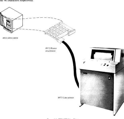
The IBM 4973 Modell and Model 2 Line Printers (Figure 1-1) use a character belt to provide from 80 to 414 lines per minute printed copy.
The 4973 Model 1 Line Printer operates at nominal speeds of 155, 120, or 80 lines per minute. The Model 2 operates at nominal speeds of 414, 300, or 235 lines per minute. The operating speed of the two models is based on a character set length of 48, 64, and 96 characters respectively.
4953/4955/4959
-4973 Printer attachment
Chapter 1. Introduction
Both models of the printer connect to the IBM 4973 Attachment card (a prerequisite for the 4973) which is located in one of the following rack mounted units:
• IBM Series/l Model 3 4953 Processor • IBM Series/l Model 5 4955 Processor
• IBM Series/l 4959 Input/Output Expansion Unit
4973 Line printer
Figure 1-1. IBM 4973 Line Printer
[image:8.620.69.557.213.679.2]PRINTER FUNCTIONAL DESCRIPTION
The IBM 4973:
• Is available in two models, 1 and 2, to provide various printing speeds
• Uses a print belt of various character set lengths • Is controlled by a cycle stealing attachment • Prints up to 132 characters per line (cpl) • Prints 10 characters per inch (cpi) • Spaces 6 or 8 lines per inch (lpi) • Has paper jam detection
• Has variable width forms tractor • Has an external forms stand (model 1)
• Has a forms stand enclosure (model 2)
• Has a control panel consisting of Ready, Printer Check, and Forms Check indicators and three switches for Space, Restore, and Enable/Disable The print speed of the 4973 model 1 and model 2 is dependent on the character set length (number of characters in the set). The following chart shows the nominal line per minute speeds of the two models for the various character set lengths available:
4973 Printer attachment feature
Character 4973 4973
Set Model I Model 2
48 155 LPM 414 LPM
64 120 LPM 300 LPM
96 80 LPM 235 LPM
ATTACHMENT FUNCTIONAL
DESCRIPTION
The attachment feature card:
• Connects the printer to the processor
• Transfers characters from the processor storage buffer to the printer through a belt translator • Controls forms movement
• Initializes to the EBCDIC Character Set (see Appendix A)
Note. The using system's program defines the length of
the forms and the overflow line on the form. When the overflow line is reached, forms movement and printing are stopped and an 'exception interrupt' is issued. Forms movement and printing resumes on the next 'Start' command.
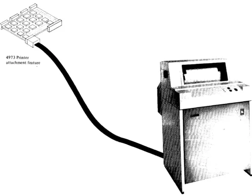
Figure 1-2. 4973 Line Printer and Attachment
1 - 2 GA34-0044
I l
[image:9.617.46.542.322.706.2](~
(
BASIC COMPONENTS
The IBM 4973 Line Printers consist of three basic components:
• Printer • Carriage • Console
Printer
The printing unit consists of a 132 print position platen, print belt, ink ribbon, and print hammers (66 print hammers for model 1 and 132 print hammers for model 2). Printing is accomplished by the print hammers which selectively force the paper against the inked ribbon and the print belt. The print hammers are selected through the belt translator when the desired character on the belt is in the correct print position.
Carriage
Both models of the 4973 have a pin feed carriage which will handle up to six part forms. (See Appendix B for forms requirements.) The carriage will move the forms at either 6 or 8 lines per inch (lpi) under program control. Forms may also be skipped under program control at the rate of 12 inches per second.
Comole
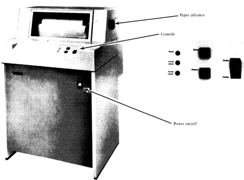
The printer console (Figure 1-3) consists of the following:
1. Indicators
Ready-The printer is ready to execute system commands
Printer Check-An error has occurred during a print operation
Forms Check-Either there are no forms in the printer or the forms failed to move under program control
Paper advance
Figure 1-3. Printer Console
[image:10.623.68.562.288.652.2]2. Switches
Enable/Disable-When in the Enable position, the printer will accept and execute commands from the system. The switch must be in the Enable position to print. To make the printer Not Ready, place this switch in the Disable position. To reset an error, move the switch to Disable then to Enable. Some errors require operator intervention such as 'end of forms' or 'forms jam'.
Carriage Restore-The carriage is positioned to line one of the forms. This switch is only active when the printer is Not Ready. With the cover open, only the vertical forms control is set to line 1 of the form. The cover must be closed to move the forms to line one.
Carriage Space-The carriage moves the forms one space. This switch is active only when the printer is Not Ready. Pressing the carriage space also causes the ribbon and print belt to move.
Power-Turns mainline power to the printer on or off. This switch is located on the front of the printer stand.
Also included are paper advance knobs located on either side of the printer cover. These knobs allow the operator to manually move the forms.
I - 4 GA34-0044
I \
(
c
Chapter 2. Programming Input/Output Operations
This chapter discusses the flow of data to and from the printer. Specific topics are commands, condition codes, status words, and
1/
0 instructions.DATA TRANSFER OPERATIONS
Data is transferred on the I/O channel, between the processor and the attachment, in a parallel operation (16 data bits plus 2 parity bits). The number of data words transferred and the direction in which they move on the channel is determined by the I/O command. The I/O command also determines whether data is transferred to or from main storage, under Direct Program Control (DPC) or in Cycle Steal (CS) mode.
DIRECT PROGRAM CONTROL (DPC)
When data is transferred under Direct Program Control, only one word of immediate data moves to or from main storage. After moving the immediate data, the processor continues processing other instructions.
CYCLE STEAL
When data is moved to or from main storage by a Cycle Steal Operation (stealing storage cycles), processing and I/O operations are overlapped. Overlapping allows the processor to execute other instructions while the printer is performing I/O operations.
Operate I/O instruction
I
Operation codeI
R2I
Function 0 4 5 7 R 10 II~
OPERATE I/O INSTRUCTIONS
The following description is an overview of the Operate I/O instruction. Refer to the Processor Description Manuals listed in the "Prerequisite Publications Section" in the preface for a more detailed description.
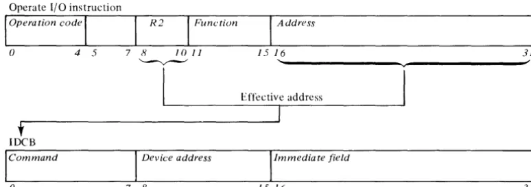
All input/output operations between the processor and the printer are initiated by an operate I/O instruction. An address field (bits 16-31) and the R2 field (bits 8-10) in the Operate I/O instruction (Figure 2-1) point to a processor storage location containing an Immediate Device Control Block (lDCB).
The IOCB is a two-word block of storage that contains the device directed I/O commands. Before issuing the I/O instruction for an operation, the command field of the IDCB (bits 0-7) must be set, along with a device address (bits 8-15), and any field of immediate data required by the command in the IDCB (bits 16-31). The information specified in the immediate field depends on the command to be performed. The device address of the 4973 is limited to 128 (0-127) possible device address combinations. Bit 8 of the Device Address Field in the IDCB must be zero. Refer to the IBM Series/l Model 5 4955
Processor and Processor Features Description,
GA34-0021 or the IBM Series/l Model 3 4953
Processor and Processor Features Description,
GA34-0022, for a more detailed description of the I/O instruction.
I
Address15 16 31
'---v---I
Effective addresst
IDeB
Command Device address Immediate field
o 7 8 15 16 31
Figure 2-1. Operate I/O instruction and IDCB format
[image:12.618.119.506.521.657.2]USING THE IDCB
An Immediate Device Control Block (lDCB) is required for every I/O command issued to the printer. The format of the IDCB is shown in Figure 2-2. Before issuing an I/O instruction, an I/O command must be stored in the associated IDCB. The immediate data field of the IDCB should contain either a data word or a DCB (device control block) address. I/O commands that execute under direct program control require a data word, while the commands that execute in cycle steal mode require a DCB address.
IDCB (immediate device control block) Command field Device address field
x X X X X X X X 0 X X X X X X X
o 7 8 15
----..--_
....
;00-7F
Immediate data field
OCB address/immediate data word
16 31
Figure 2-2. IDCB Format Control
2 - 2 GA34-0044
USING THE DCB
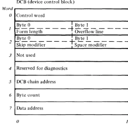
A Device Control Block (DCB), comprised of eight contiguous words in main storage, must be reserved for every I/O operation that moves data in Cycle Steal mode. A separate DCB is required for:
• A Start command
• A Start Cycle Steal Status command
• All printer operations included in a DCB command chaining sequence
Device parameters that define and control the I/O operation must be stored in each DCB. (See Figure 2-3.) The bit significance of each DCB word will be covered in "DCB Format" later in this chapter.
Word
o
2
3
4
5
6
7
DCB (device control block)
Control word
Byte 0 I Byte 1
Porm length - - -
-t
Overflow line - - -Byte 0 I Byte 1Skip modifier - - -
fSpace~lOdifier
- - -Not usedReserved for diagnostics
DCB chain address
Byte count
Data address
o 15
Figure 2-3. Device Control Block
[image:13.617.68.264.205.304.2] [image:13.617.324.536.226.435.2](
INPUT/OUTPUT COMMANDS
The I/O command, stored in the IDCB, determines whether Direct Program Control or Cycle Steal mode is used to move data between main storage and the attachment during an I/O operation. The attachment responds to the following I/O commands:
Direct Program Control (DPC)
1. Prepare 2. Device reset 3. Read Device ID
Cycle Steal Mode (CS)
1. Start
2. Start Cycle Steal Status
Operate I/O instruction
loperation code
I
R2I
Functiono 4 5 7 8 10 11
~
Command Execution Under DPC Mode
When the printer unit executes a Prepare, Device Reset, or Read ID command, a word of data is moved to or from the immediate data field of the IDCB in main storage. After execution of the command, the attachment reports a condition code that indicates whether the I/O operation succeeded or failed. See "Condition Codes" in this chapter. Processing operations are halted while the I/O operation is in progress. (See Figure 2-4.)
Note. I/O commands that move data under DPC do
not cause interrupts.
I
Address15 16 31
'---v---~'
1L-________
~E~;t~.~~c~ti~Vre~ad~d~r~es~.s---~
I
t
IDCB (immediate device control block)
Command field Device address field Immediate data field
x X X X X X X X 0 X X X X X X X
o 7 8 15 16 31
~~---~---' ~~---~---~'
Leve I Status Register (Note 1)
101
LfLJ
t
"
Note 1. LSR BIt 0 even mdicator Bit 1 carry indicator Bit 2 overflow indicator
Condition code
Figure 2-4. Direct Program Control I/O Operation
4973
,.
Printer
, and
Attachment
[image:14.618.115.506.241.558.2]Prepare Command
Before the printer, via the attachment, can execute interrupt types of commands, it needs interruption parameters which control these commands. These parameters, stored in the IDCB immediate fields associated with a Prepare command, contain the level on which the attachment is to interrupt (bit 27-30), and an interrupt enable (bit 31), and are transferred to the attachment upon execution of Prepare commands. If the I-bit (bit 31) equals 1, the printer can interrupt. If the I-bit equals 0, the printer cannot interrupt. The Prepare command operates under DPC and does not itself cause an interrupt.
IDeB (immediate device control block) Command field Device address field
o
1 0 0 0 0 0 0 X X X X X X Xo Prepare 7 8 15
~,---v---~ ''---v---~~
60 00-7F
,Immediate data field
Zeros Level
16 26 27 3031
Device Reset
A Device Reset command will:
Stop all cycle stealing, printing and carriage movement
• Reset Control, Status, and Pending interrupts • Reset the ISB
• Stop the print belt • Halt any Start command • Not alter forms length
The Device Reset does not use or check the immediate data field of the IDCB. The command code and device address supply all needed information.
Note. Issuing a Device Reset while the carriage is
moving requires forms alignment by the operator.
IDeB (immediate device control block) Command field Device address field
o
1 1 0 1 1o
X X X X X X Xo Device reset 7 8 15
6F 00-7F
IImmediate data field
Not used
16 31
2 - 4 G A 34-0044
Read Device ID
The Read Device 10 command operates under DPC and transfers the device 10 from the printer attachment into the immediate data field of the IDCB associated with that command. If the printer is busy or an interrupt is pending, condition code 1 is returned. No interrupt results from the Read Device command. The 4973 ID, 0306 HEX, is placed in the immediate data field.
IDeB (immediate device control block) Command field Device address field
0 0 1 0 0 0 0 0 0 X X X X X X X
0 , ., 7 8 , 15
~
20 00-7F
Immediate data field
o
0 0 0 0 0 1 1 0 0 0 0 0 1 1 016 23 24 31
03 Device ID 06
Command Execution in Cycle Steal Mode
The Start command and the Start Cycle Steal Status command are interrupt-causing commands that move data in Cycle Steal mode. When the attachment receives and accepts either of these commands, it reports a condition code to the processor and begins command execution. The processor continues with other operations while the attachment is "busy" with the I/O operation. When the I/O operation is completed, the attachment sends an interrupt request to the processor. At interrupt presentation time, the attachment reports a condition code and transfers an interrupt ID word containing status information to the processor. See "I/O Status Information" in this chapter.
The immediate data field of an IDCB containing either a Start command or a Start Cycle Steal Status command must point to a Device Control Block (DCB). See Figure 2-5. The DCB must contain the control information and device parameters that are required to execute an I/O operation in Cycle Steal mode.
(
\
{
c
(
c
Operate 110 instruction
I
Opero tion codeI
R2I
Function Address() 4 5 7 H JOJJ J 5 J 6
' - v - - - " v
I
Effective addressI
•
IDCB (immediate device control block)
Command field Device address field Immedia te data field
x X X X X X X X 0 X X X X X X X DCB address
() 7 H 15 16
Leve I Status Register (Note 1)
cjol
SLJ
t
Note 1. LSR Bit 0 even indicator Bit 1 carry indicator Bit 2 overflow indicator
"
J
Device Control Block Format
DCB (device control block)
DCB address
(hexadecimal) Control word
Byte 0 I Byte I
~---t;;----Form length I Overflow line Byte 0 ---! Byte~ _
-Skip modifier I Space modifier Not used
Reserved for diagnostics
DCB chain address
Byte count
Data address
()
Condition code
Figure 2-5. Cycle Steal I/O operation
3J
31
"
Word
()
- -
J- 2 Chained to DCB
3
r-~l
1
4 1
LJ
1 1 1
5 ___ I
6 Data area
7
·1
1
15 ~r"" ~
t
4973 Printer and Attachment
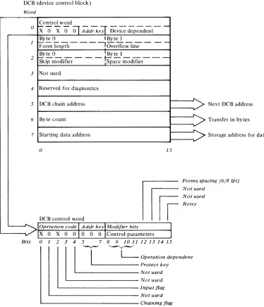
[image:16.615.56.559.45.617.2]DCB Format
The DCB (Figure 2-6) contains eight contiguous data words. DCB words 1 through 7 depend on the configuration of bits 8 through 11 of the Control Word (DCB) word 0).
DCB Word O-Control Word
The Control word is the first word of the DCB. It is a 16-bit word that explains the cycle stealing operation, and contains two distinct bytes of control parameters to be used with the particular Start command to be performed. Figure 2-6 shows the DCB and Control Word O.
Bits 1 3 4-Not Used. These bits are not supported and must be zero.
DCB (device control block)
Word
Control word
Bit O-Chaining Flag. When set this bit indicates a command chaining operation. After completing the current DCB operation, the attachment will not interrupt but will fetch the next DCB pointed to by the Chain Address in DCB word 5. Command Chaining is valid only for a Start Command with a modifier of '0000' and is ignored and not checked for the other commands.
Bit 2-Input Flag. This bit indicates the direction of the Cycle Steal operation: 0
=
out of main storage, 1=
into main storage.Bits 5 6 7-Address Key. This is a 3-bit key presented by the attachment during data transfers to ascertain storage access authorization. An invalid
0
x'O
X 0
Ol
Addr ke~ Device
dependent--1
2
3
4
5
6
7
- - - - I '
v
BIts
2 - 6 GA34-0044
Byte 0 I Byte I
Form kngth - - - , Overflow li;;- - - -Byte 0 I Byte I
skip modifier - - - mace modifier- -
-Not used
Reserved for diagnostics
DCB chain address
>
Byte count
Starting data address
v-a
15mf
Forms spa Not used Not used Retry
DCB control word
Operation code
I
Addr keylModifier bitsX 0 X 0 010 0
o
IControl parameterso
1 2 3 4 5 7 8 9 1011 12131415I
L-
Operation dependentII
' - v - ' ' - - v - - "
' - - - Protect key
~-Notused
L . - - - -Not used
' - - - I n p u t flag ' - - - Not used
' - - - Chaining flag
Figure 2-6. DCB and Control Word 0
Next DCB address
Transfer in bytes
Storage address for data
cing (6/8 [pi)
( l
\. j
[image:17.612.114.488.272.708.2]c
(
c
addresss key will result in a protect check.
Bits 8 9 10 II-Operation Dependent. Used in conjunction with each other, these bits specify various operations. The following chatt shows the bit configuration, the operation and the DCB words used for each operation. The Operations are discussed later in this text.
Bits
8 9 JO JJ Operation Words Used
0 0 0 0 Carriage Control and Print 2,5,6,7 Line
1 0 0 0 Set Forms Parameters, 1, 2, 5, 6, 7 Carriage Control, and Print
Line
0 1 0 0 Initialize Belt Translator 5, 6, 7
0 0 1 0 Transfer Belt Translator 5,6,7
0 0 0 1 Reserved for Diagnostics 4,5,6,7
Bit 12-Forms Spacing. Used when bits 8, 9, 10, and 11 equal 1000, bit 12 specifies 6 lines per inch when set to
°
or 8 lines per inch when set to 1.Bits 13 and 14-Not used.
Bit IS-Retry. When this bit is on, the attachment will attempt to complete execution of the last Start I/O command issued. If this bit is on, the remainder of the DCB must be the same as the DCB being executed at the time of the exception interrupt (the printer attachment knows what step of the execution was in process when the exception occurred, DCB transfer, data transfer, carriage movement or printing).
The attachment executes the necessary steps for completing the Start I/O command. The entire DCB is transferred to the printer. The data is transferred only if required. If the previous Start I/O command was successfully completed, the Retry Bit is ignored and the DCB is executed. After a Power On Reset, the command is executed as a normal DCB, and the other words in the DCB are checked and used if required. This command is terminated with a normal Device End interrupt, unless further exception conditions are detected and reported by an exception interrupt.
DCB Word I-Forms Parameters
Byte
°
of DCB word 1 is the new form length. If it is less than the current line position, the current line position is set to line 1 of the form.Byte 1 is the line where the printer is to stop form movement and/or printing and post an exception interrupt with bit
°
on in the ISB. Cycle Steal Status word 1 will have the overflow bit (11) set on. A Start Cycle Steal Status I/O command is issued to determine how many lines are required to complete the previous carriage operation (the residual line count) and/or the current line position status. Overflow interrupt is inhibited if Byte 1=
°
or is greater than the form length (Byte 0).DCB Word 2-Carriage Control
The Carriage Control Word specifies whether a skip or space is to take place. For a skip, the attachment calculates how far the forms must be moved to get to the specified line. To space, the user tells the attachment how many lines to move. The speed of the forms movement is the same regardless of the modifier used.
Byte
°
of the carriage control word is the skip. Ifthis byte has a value of up to the form length, the forms will move to the specified line on the next form. If the skip modifier is greater than the form length, an interrupt is posted and the DCB specification check is set in the ISB.
If byte
°
=
0, byte 1 is inspected for a space. Ifbyte 1
=
0, no forms movement will take place. If the space modifier is greater than zero the forms will move the number of lines specified. (If byte°
is greater than zero, byte 1 is not checked.)The maximum number of lines the forms can be moved with either a skip or space command is 255.
DCB Word 3-Not Used
DCB Word 4-Reserved for Diagnostics
DCB Word S-Chaining Address
The Chaining Address is the location of the next DCB table to be executed. If the Chaining Address is odd, an interrupt is posted and a DCB specification check is set in the ISB. The Chaining Address is not checked unless the chaining flag is on in a valid control word.
DCB Word 6-Byte Count
This word specifies the byte count for a particular operation. If the byte count = 0, no data is transferred. If the byte count is greater than the maximum allowed for a particular operation, an interrupt is posted and a DCB specification check is set in the ISB.
DCB Word 7 -Data Address
Word 7 is the system storage address for the data associated with the operation to be performed.
Operations
The printer operations depend on the configuration of bits 8, 9, 10, and 11 of the Control Word (DCB Word 0). These bit configurations are explained in the following text.
Bits 8 9 10 1 1 = OOOO-Carriage Control and Print Line. Transfer one print line and carriage control data from the processor to the attachment. The input flag, bit 2, must be zero. This operation uses DCB Words 2, 5, 6, and 7. The maximum byte count for this operation is 132.
Bits 8 9 10 1 1 = 1000-Print and Carriage Control. Transfer all data necessary to print one line, specify forms length, specify overflow line and line spacing, and move the carriage.
Bit 12 of DCB Word 0, the Control Word, is used to indicate the forms spacing. The carriage spaces 6 lines per inch when bit 12 equals 0; and 8 lines per inch when bit 12 equals 1.
Note. If the line spacing is changed on other than line 1
of the form, the forms may have to be manually adjusted for line 1.
Bits 8 9 10 1 1 = 01 OO-Initialize Belt Translator.
Initialize the belt translator with the data for the print belt character sets (48, 64, or 96). The 96 character set prints 94 characters because belt positions 87 and 88 are unprintable characters.
This operation will occur only if the input flag, bit 2, of the Control Word equals 0; and the byte count is less than 8.
DCB Words 5, 6, and 7 are used for this operation.
Bits 8 9 10 11 = 0010-Transfer Belt Translator.
The transfer of belt translator data between main storage and the printer attachment. The direction of data flow is dependent on the Input flag. The belt translator data field includes the print belt position to be printed for each of the possible 256 HEX codes.
2 - 8 G A 34-0044
An entry of zero indicates that no printing is required for that particular HEX code. The byte count for this operation is from 0 to 256. Transfer Belt Translator is used to load a translator other than the standard translator (see Appendix B).
Bits 8 9 10 1 1 = 0001 -Reserved for Diagnostics.
Programming Considerations When Using the DCB 1. All words in the DCB are fetched. The contents
of the words must be specified correctly.
2. The DCB address, chain address, and the status address must be even.
DCB Command Chaining
DCB command chaining is executed when the current DCB comes to a normal completion and a new DCB is fetched without issuing a new Operate I/O instruction.
The first DCB in the chain contains the address of the next DCB. As each operation in the sequence is completed, the attachment uses the chain address stored in the current DCB to select the next DCB. The chained-to DCB is examined to determine which operation is next in the sequence and whether the associated device parameters are valid. DCB command chaining operations continue until a DCB is fetched having the chaining bit in the control word (DCB word 0) set to zero. This indicates the last operation in the chain.
If an error occurs, chaining to succeeding DCBs is automatically suspended and the attachment sends an interrupt request to the processor. The attachment does not request an interrupt until the printer has completed the last operation in the chain. By using command chaining, the processing time required to execute I/O operations is reduced.
(
'\c
.. ·."
.~- .#
(
c
Start Command
The Start command initiates all printer operations that transfer data to or from main storage in cycle steal mode. As a result of initiating this command, an interrupt request is presented to the processor when the operation is completed.
DCB Word 0, Control Word, contains the applicable control parameters for a given operation. See "DCB Word O-Control Word".
Note. A Start command issued to print or space while the printer is Not Ready, will cause an interrupt with condition code 2 (Exception) and bit 0 (Device Status Available) set in the ISB. The start command will not be executed.
The Operate I/O instruction must point to an IDCB containing a Start command and an immediate field containing the address of the DCB.
IDCB (immediate device control block) Command field Device address field
o
1 0 0 0 0 0 X X X X X X Xo Start I/O 7 8 15
70 00-7F
,Immediate data field DCB address
16 31
~~---~---'
I
Ward
()
DCB (device control block)
Control word
Byte 0 ' Byte 1
~r-;;tength-
- - : Overt1ow lin;- --2 !y~O _ _ _ _ _ -t-Byte..!.... _ _ _ _ _
Skip modifier I Space modifier
3 Not used
4 Reserved for diagnostics
5 DC'B chain address
6 Byte count
7 Da ta address
o 15
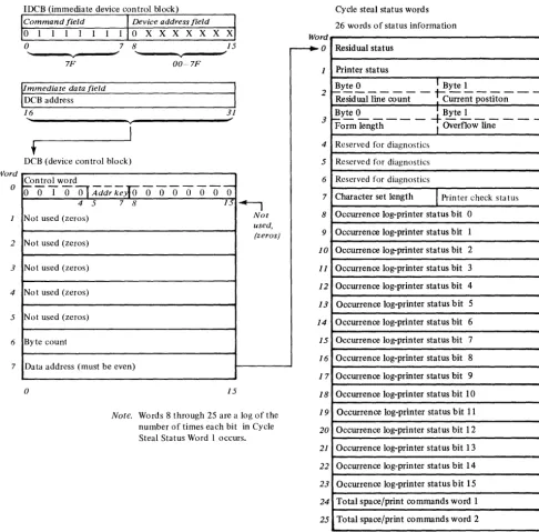
Start Cycle Steal Status Command
The Start Cycle Steal Status command initiates the transfer of up to 26 words of status information from the printer attachment to main storage. This status information is used to determine why a given command did not execute properly. The main storage address is specified in word 7 of the applicable DCB. This command operates in cycle steal mode and
Word o 2 3 4 5 6 7
IDCB (immediate device control block)
Command field Device address field
0 1 1 1 1 1 1
o
X X X X X X Xo
7 8 15... ~ ... ~
v v
7F 00~7F
IImmediate data field
DCB address
I
16 31
" ~
v
I
t
DCB (device control block)
Control word
~OTO~Mdr~roooooooO
4 5 7 8 fJ ~
Not used (zeros) Not
used,
Not used (zeros) (zeros)
Not used (zeros)
Not used (zeros)
Not used (zeros)
Byte count
Data address (must be even)
o 15
Note. Words 8 through 25 are a log of the
number of times each bit in Cycle Steal Status Word I occurs.
causes the attachment to present an interrupt request when execution is complete.
The Start Cycle Steal Status command requires 1) an operate I/O instruction with the address of an IDCB, 2) an IDCB with the address of the DCB, and 3) a DCB. Figure 2-7 shows the formats of the IDCB, DCB and 26 words of status information.
Word
o
---.
1 2 3 4 5 6 7 8 1 9o
1 1
1 2
1 3
1 4
1 5
1 6
1 7 18 19 20 21 22 23 24 25
Cycle steal status words
26 words of status information
Residual status
Printer status
Byte 0 I Byte 1
R~siduailin;-co~nt
-~c;;-ent
postito;- --~yte ~ _ _ _ _
-+
Byte~ _ _ _ _ _ Form length I Overflow lineReserved for diagnostics
Reserved for diagnostics
Reserved for diagnostics
Character set length
I
Printer check status Occurrence log-printer status bit 0Occurrence log-printer status bit 1
Occurrence log-printer status bit 2
Occurrence log-printer status bit 3
Occurrence log-printer status bit 4
Occurrence log-printer status bit 5
Occurrence log-printer status bit 6
Occurrence log-printer status bit 7
Occurrence log-printer status bit 8
Occurrence log-printer status bit 9
Occurrence log-printer status bit 10
Occurrence log-printer status bit 11
Occurrence log-printer status bit 12
Occurrence log-printer status bit 13
Occurrence log-printer status bit 14
Occurrence log-printer status bit 15
Total space/print commands word 1
Total space/print commands word 2
o 15
Figure 2-7. Start Cycle Steal Status Command
2 - 10 GA34-0044
f
\.
I
[image:21.623.44.530.152.631.2]-(
c
I/O STATUS INFORMATION
After execution of a given command in either DPC or cycle steal mode, status information will be reported to the processor for analysis of that command's execution. There are three types of data that can make up this status information:
• Condition codes • Interrupt ID word • Cycle Steal Status
Condition Codes
A condition code is reported to the processor for every Operate I/O instruction and upon presentation of a priority interruption. The condition code is available in the even, carry and overflow bit positions of the Level Status Register (LSR).
Condition codes reported at the completion of an Operate I/O instruction are:
Condition Code
o
1 2 3 4 5 6 7 MeaningDevice not attached Busy
Busy after reset Command reject Not used
Interface data check Not used
Satisf actory
Condition codes reported during priority interruptions are:
Condition Code Meaning
0 Not used
1 Not used
2 Exception
3 Device end
4 Attention
5 Not used
6 Not used
7 Not used
Condition Code 2-Exception
This code is reported when an error or exception condition is associated with the interrupt. This condition is described in the Interrupt Status Byte (ISB) and the Cycle Steal Status Words (Figure 2-7).
Condition Code 3-Device End
This code is reported when no error exception or attention conditions occur during the I/O interruption. A normal termination of the operation has occurred.
Condition Code 4-Attention
This code is reported when the printer goes Ready after being in the Not Ready state.
Along with the interrupt condition code, the attachment also transfers an interrupt ID word which
provides additional information on interrupting conditions.
Interrupt ID Word
Acceptance of an I/O interrupt causes the attachment to place the ID word in register 7 (R7) of the interrupted level. For condition code 2 the Interrupt ID word consists of the Interrupt Status Byte (ISB) and the address of the interrupting device. The first byte will be zero for all other condition codes. The format is as follows:
Interrupt I D word
ISB Device address
o
0 0 0 0 0 0 0 0 X X X X X X Xo 7 8
Interrupt Status Byte
The ISB stores accumulated status information. The format of the ISB is:
Bit O-Device Dependent Status Available Bit I-Delayed Command Reject
Bit 2-Not Used
Bit 3-DCB Specification Check Bit 4-Storage Data Check Bit 5-lnvalid Storage Address Bit 6-Protect Check
Bit 7-lnterface Data Check
15
Bit O-Device Dependent Status Available. Additional status information (residual address and status bits), is available in the Cycle Steal Status Words (Figure 2-7). A Start Cycle Steal Status Command must be issued to get this information.
Bit I-Delayed Command Reject. The 4973 cannot execute a command because of an incorrect parameter in the IDCB or the printer is offline.
This bit is only set in the ISB when the attachment is incapable of recording the condition with condition codes during the I/O instruction. The operation in progress is terminated and an interrupt request is generated. Condition code 2 is reported at interrupt accept time. The Residual Address is not relevant to error recovery (see Cycle Steal Status Word 0).
Bit 2-Not used (always 0).
Bit 3-DCB Specification Check. The 4973 cannot execute the command because a parameter in the DCB is incorrectly specified to perform the desired operation.
Example: An odd byte chaining address, an odd address for start cycle steal status, an invalid command in the control word or an incorrect count.
Condition code 2 is reported at interrupt accept time. The Residual Address will be the last word of the DCB.
Bit 4-Storage Data Check. Storage Data Check is set during cycle steal output operations only. It
indicates that the storage location accessed during the current output cycle contained bad parity. The parity in main storage is not corrected. The attachment issues the status in the ISB and terminates the operation.
Condition Code 2 is reported at interrupt time.
Bit 5-Invalid Storage Address. Set on as a result of a cycle steal I/O operation when the main storage address presented by the attachment for data or DCB access exceeds the storage size fitted on the system. The attachment records the status and terminates the operation. Condition Code 2 is reported at interrupt time.
Bit 6-Protect Check. Set when the attachment attempts to access a storage location without the correct storage address key. (Refer to the IBM
Series/l Model 5 4955 Processor and Processor
Features Description, GA34-0021, or the IBM
Series / 1 Model 3 4953 Processor and Processor
Features Description, GA34-0022). Condition code 2 is
reported at interrupt time.
Bit 7-Interface Data Check. This bit is set when a parity error is detected on a cycle steal data transfer. The condition can be detected by the attachment or by the channel. In either case, the operation is terminated and an interrupt is reported to the processor.
Condition code 2 is presented at interrupt accept time.
2 - 12 GA34-0044
Cycle Stelll Status
Up to 26 words of status information are transferred to the processor upon execution of the Start Cycle Steal command. Normal error recovery requires only the first 8 status words being transferred. This is accomplished by using a byte count of 16. This information has the following format and meaning:
Word
o
2
3
4
5
6
7
8
Residual address
Printer status
Byte 0 1 Byte 1
1 - - - 1 - - -
-
-Residual line count I Current position
~y.!:. ~ _ _ _ _
-t-
Byte2. _ _ _
-Form length I Overflow lineReserved for diagnostics
Reserved for diagnostics
Reserved for diagnostics
Character set length
1
Printer check statusOccurrence log
25~r=
____________________________
~o 15
Word O-Residual Address
[:
(
c
Word I-Printer Status
When bit 0 of the ISB is set ON, Printer Status Word 1 will further explain the condition that caused the exception interrupt (CC2). This status will not be reset until the next Start command other than a Start Cycle Steal Status command. The information in the Printer Status word is not necessarily current but reflects the status at the time of the last non-cycle steal status interrupt.
Bit 9-External Interface Check. When the exception is posted, the attachment does a diagnostic checkout of the external cable interface. This check bit is set if the cable is disconnected, a grounded or an open signal line exists, or there is a bad line driver.
Bit IO-Printer Interface Check. When the 4973 attachment turns interface lines on or off it checks to see if the appropriate lines switched on the printer interface. If a line does not switch properly, bit lOis Bit O-Printer Power Off. The attachment receives set.
no response from the printer when a data wrap sequence is executed. This means the power to the printer is off.
The remaining status bits in the device status word may not be valid if bit 0 is on.
Bit I-Attachment Storage Check. The attachment has detected an error when accessing the controller storage.
Bit 2-0ver Temperature. The Printer has detected an overtemperature condition.
Bit 3-Disabled. The Enable/Disable switch is in the Disable position.
Bit 4 -Throat Open. The printer throat is open.
Bit 5-Cover Open. The printer cover is open.
Bit 6-0ff Line Test Mode. The printer is executing off line tests and is not available for system use. When off line testing has ended an attention interrupt is posted.
Bit 7-Forms Jammed. If the forms should be moving under program control but no movement is detected, this bit is set. When this check occurs, the previous space command may have failed.
Bit 8-Hammer Check. If the attachment detects a hammer active when it should be inactive (or inactive when it should be active), this bit will be set.
Bit II-Overflow. This bit is set if the forms have stopped on the overflow line. If the forms were to move beyond the overflow line there is a residual line count in Device Status word 2. No printing occurs for the current DCB. The residual address can be anywhere in the print line.
Bit 12-End of Forms (EOF). At the completion of a forms movement operation the forms switch is checked. If the switch is open (indicating no forms), the End of Forms bit is set and an exception interrupt is posted. No printing is attempted when this condition is detected. The EOF condition occurs when there is approximately 152 mm (6 inches) of paper remaining in the printer.
Note. If a multi-line forms movement command has
been given in the command for which this exception interrupt is given, the amount of paper remaining in the printer may be reduced by the number of lines the command spaced. Print commands must be issued with no spacing in order to print on any of the remaining paper.
Bit 13-Belt Sync Check. A 'belt home' pulse did not occur at the proper time.
Bit 14-Belt Speed Check. The print be:t did not come up to speed within 2 seconds after the print command.
Bit 15-4973 Model 2 Installed. This bit is on when a 4973 Model 2 is installed. No exception interrupt will be caused by this bit.
Word 2-Residual Line Count-Current Position The Residual Line Count (Byte 0 of Status word 2) contains the number of lines the forms would have to move to complete the forms control of the last operation. This count is not valid if an error occurred during the transfer of the last DCB. Normally this count is zero.
On an overflow interrupt, if the carriage is to move beyond the overflow line, the remaining lines required to be moved to complete the operation are in the Residual Line Count. If a check such as hammer check or sync check occurs during forms movement, the number of lines that remain to be moved to complete the forms operation are in the Residual Line Count.
Current forms position (Byte 1 of Status word 2) always contains the current line position of the forms (1-255). This position will not be changed by manual movement of the forms.
Word 3-Forms Length-Overflow Line
The form length (Byte 0 of Status word 3) and the overflow line (Byte 1 of Status word 3) are the most recent forms parameters successfully transferred to the printer from the system. If no forms parameters have been transferred, the default values of form length equal to 66 and overflow line equal to 0 will be presented.
Word 4, 5, and 6-Reserved For Diagnostics
Word 7 -Character Set Length
Byte 0, the Character Set Length, is a binary count determined by the printer attachment. The count is normally 48, 64, or 96 (30, 40, 60 HEX) to represent the number of characters detected between home pulses. The count is set to zero after power on reset until the belt has been brought up to speed and into sync.
2 - 14 GA34-0044
STATUS AFTER POWER AND 'RESETS
During Power On Reset the following actions occur: • The printer performs Internal Register, Data Flow
and Storage Tests. The printer will remain Busy if these tests fail. If they are successful the printer initializes the Belt Translator Buffer with the specified character set and clears all internal buffer locations.
• The forms length is initialized to 66 lines.
• The overflow line is initialized to line O. The forms are assumed to be positioned on line one.
• The residual address is set to zero.
During System and Printer Resets, or Halt 1/0:
• Printing stops.
The printer may stop part way through printing a character or spacing a line. If the forms stop between lines, registration must be restored by the operator.
• All pending interrupts are reset. If the printer was in the process of updating the storage address registers (Residual Address) when the reset occurs, the Residual Address may be indeterminate.
• The Belt Translator buffer will not be altered.
I \
" i
-Appendix A. EBCDIC Character-Hexadecimal Equivalents
C
The following table contains the Standard EBCDIC character set and EBCDIC codes for the 48, 64, and 96 character print belts. The 48 character set consists of belt positions 1 to 48, the 64 character set consists of 1 to 64, and the 96 character set consists of 1 to 96.
Belt EBCDIC Belt EBCDIC
Position (Hex) Character Position (Hex) Character
1 Fl 49 4A ¢ Cent Sign
2 F2 2 50 4C < Less than sign
3 F3 3 51 40 ( Left Parenthesis
4 F4 4 52 4F I Logical Or
5 F5 5 53 5A Exclamation Point
6 F6 6 54 5D Right Parenthesis
7 F7 7 55 5E Semicolon
8 F8 8 56 5F Logical Not
9 F9 9 57 EO \ Reverse Slant
10 FO 0 58 60 Underscore
11 7B # Number Sign 59 6E
>
Greater than Sign12 7C @ At Sign 60 6F ? Question Mark
13 61 / Slash 61 7A Colon
14 E2 S 62 7E Equal Sign
15 E3 T 63 7F Quotation Mark
16 E4 U 64 79 Grave Accent
17 E5 V 65 6A
+
Broken Vertical Line(.
18 19 E7 E6 W X 66 67 81 82 a h20 E8 y 68 83 c
21 E9 Z 69 84 d
22 50 & Ampersand 70 85 e
23 6B Comma 71 86
24 6C (X) Percent Sign 72 87 g
25 Dl J 73 88 h
26 D2 K 74 89
27 03 L 75 CO Open Brace
28 D4 M 76 00 Closing Brace
29 D5 N 77 AI Tilde
30 D6 0 78 91 j
31 07 P 79 92 k
32 08 Q 80 93 I
33 D9 R 81 94 m
34 60 Minus Sign, Hyphen 82 95 n
35 5B $ Dollar Sign 83 96 0
36 5C
*
Asterisk 84 97 p37 Cl A 85 98 q
38 C2 B 86 99 r
39 C3 C 87 18 (Unprintable) (9 Cancel
40 C4 D 88 9C (Unprintable) tl Lozenge
41 C5 E 89 A2
42 C6 F 90 A3
43 C7 G 91 A4 u
44 C8 H 92 A5 v
45 C9 93 A6 w
46 4E + Plus Sign 94 A7 x
47 4B Period, Decimal 95 A8 Y
48 7D Apostrophe, Prime 96 A9 z
C~
A - 2 G A 34-0044
(
\c:
c
The Transfer Belt Translator operation causes transfer of a belt translator table defining representation of characters on the standard belt. (The standard belt along with EBCDIC HEX codes of Appendix A is self initialized and does not require this operation.) The location of the translator table is defined by DCB Word 7. The relative address within the table represents the character HEX code while the contents of the table location identify the position (in HEX) of the character on the print belt relative to the home pulse position. Any translator table location that contains a HEX code of '00' will result in printing a blank (no character printed) for the character code represented by the table location.
HEX HEX HEX HEX
HEX Belt HEX Belt HEX Belt HEX Belt
ADD Pas ADD Pas ADD Pas ADD Pas
00 00 20 00 40 00 60 22 01 00 21 00 41 00 61 00 02 00 22 00 42 00 62 00 03 00 23 00 43 00 63 00
04 00 24 00 44 00 64 00 05 00 25 00 45 00 65 00 06 00 26 00 46 00 66 00 07 00 27 00 47 00 67 00
08 00 28 00 48 00 68 00 09 00 29 00 49 00 69 00 OA 00 2A 00 4A 31 6A 41 OB 00 2B 00 4B 2F 6B 17
OC 00 2C 00 4C 32 6C 18 00 00 20 00 40 33 60 3A OE 00 2E 00 4E 2E 6E 3B OF 00 2F 00 4F 34 6F 3C
10 00 30 00 50 16 70 00 11 00 31 00 51 00 71 00 12 00 32 00 52 00 72 00 13 00 33 00 53 00 73 00
14 00 34 00 54 00 74 00 15 00 35 00 55 00 75 00 16 00 36 00 56 00 76 00 17 00 37 00 57 00 77 00
18 00 38 00 58 00 78 00 19 00 39 00 59 00 79 40 lA 00 3A 00 5A 35 7A 3D IB 00 3B 00 5B 23 7B OB
lC 00 3C 00 5C 24 7C OC 10 00 3D 00 50 36 70 30 IE 00 3E 00 5E 37 7E 3E IF 00 3F 00 5F 38 7F 3F
Appendix B. Belt Translator
The following chart shows the contents of a translator table representative of the standard 94 character set of Appendix A. The "HEX ADD" is the relative HEX address within the translator table and is the HEX code which will cause the belt position defined by the contents of that location to be printed. For example, HEX code 4A will cause belt position 31 (HEX) to be printed (the engraved character at this position is "¢").
The maximum byte count for this operation is 256. Any HEX address that is not entered during a Transfer Belt Translator will remain unchanged.
HEX HEX HEX HEX
HEX Belt HEX Belt HEX Belt HEX Belt
ADD Pos ADD Pos ADD Pas ADD Pas
80 00 AO 00 CO 4B EO 39 81 42 Al 40 Cl 25 El 00 82 43 A2 59 C2 26 E2 OE 83 44 A3 5A C3 27 E3 OF
84 45 A4 5B C4 28 E4 10
85 46 A5 5C C5 29 E5 II 86 47 A6 50 C6 2A E6 12 87 48 A7 5E C7 2B E7 13
88 49 A8 5F C8 2C E8 14 89 4A A9 60 C9 20 E9 15 8A 00 AA 00 CA 00 EA 00 8B 00 AB 00 CB 00 EB 00
8C 00 AC 00 CC 00 EC 00 80 00 AD 00 CO 00 ED 00 8E 00 AE 00 CE 00 EE 00 8F 00 AF 00 CF 00 EF 00
90 00 BO 00 00 4C FO OA 91 4E Bl 00 01 19 Fl 01
92 4F B2 00 02 lA F2 02
93 50 B3 00 03 IB F3 03
94 51 B4 00 04 IC F4 04 95 52 B5 00 05 10 F5 05 96 53 B6 00 06 IE F6 06 97 54 B7 00 07 IF F7 07
98 55 B8 00 08 20 F8 08 99 56 B9 00 09 21 F9 09 9A 00 BA 00 OA 00 FA 00 lJB 00 BB 00 OB 00 FB 00
9C 00 BC 00 OC 00 FC 00 90 00 BO 00 00 00 FO 00 9E 00 BE 00 OE 00 FE 00 9F 00 BF 00 OF 00 FF 00
B-2 GA34-0044
(
\ \. jc
The 4973 Printer uses a forms tractor to be used with continuous single/multipart margin punched forms.
All forms must meet the following requirements:
DIMENSIONS
Minimum thickness
Maximum thickness
Minimum width
Maximum width
Minimum distance between folds
Maximum distance between folds
Maximum copies
.08 mm (.003 inches) .5 mm (.02 inches) 88.9 mm (3.5 inches) 381 mm (15.0 inches)
76.2 mm (3.0 inches)
355.6 mm (14.0 inches) original plus five
Appendix C. Printer Forms
FORMS WEIGHT
Single-ptlrt Forms
Minimum weight
Maximum weight
Multi-part Forms
Paper
Minimum
Maximum
Carbon
Minimum
Maximum
57 grams/sq. meter 15 lbs/ream (17" x 22") 90 grams/ sq. meter 24 lbs/ream (17" x 22")
41 grams/sq. meter 11 lbs/ream (17" x 22") 49 grams/sq. meter 13 lbs/ream (17" x 22")
26 grams/sq. meter 7 lbs/ream (17" x 22") 34 grams/sq. meter 9 lbs/ream (17" x 22") Remember, when using forms:
• Do not use continuous form card stock in model 1. • Do not use stapled forms.
• Do not use partially separated forms.
For more detailed information on printer forms, refer to IBM Form Design Reference Guide For
Printers, GA24-3488.
c -2 GA34-0044
( '
'- j
-(
.-
:
(
c
address, residual 2-12
address key 2-7
Appendix A. EBCDIC character-hexadecimal equivalents A-I
Appendix B. belt translator B-\ Appendix C. printer forms C-\
attachment functional description 1-2
attachment storage check 2-13
attention, CC4 2-11
basic components carriage 1-3 console 1-3
printer 1-3 belt speed check 2-13 belt sync check 2-13
belt translator B-1 byte count 2-7
carriage \-3
carriage control 2-7
carriage control and print line 2-8 chaining address 2-7
chaining nag 2-6
checks
attachment storage check 2-13
bel t speed check 2-13
belt sync check 2-13 DCB specification 2-11
delayed command reject 2-11
device dependent status 2-1 I
external interface check 2-13
hammer check 2-13
interface data check 2-12
invalid storage address 2-12
printer interface check 2-13
protect check 2-12,2-12
storage data check 2-\2
command execution in cycle steal mode 2-4 command execution under npc mode 2-3 condition codes
attention, CC4 2-\1 device end, CC3 2-11 exception, CC2 2-1\ console 1-3
control word 2-6
cover open 2-13 cycle steal 2-\
cycle steal I/O operation 2-5 cycle steal status
character set length 2-14 forms length 2-14 printer status 2-13 residual address 2-12 residual line count 2-\4
data address 2-8
data transfer operations 2-1
DCB command chaining 2-8
nCB format 2-6
DCB specification check 2-11 DCB word 0 - con trol word 2-6
delayed command reject 2-11
description
attachment 1-2
prin ter 1-2
device address 2-1
device control block 2-2 device dependent status 2-11
device end, CC3 2-11
device reset 2-4
direct program control 2-1
disabled 2-13
OPC 2-1 , 2-3
EBCDIC character-hexidecimal equivalents A-I
enable/disable 1-4 end of forms (EOI:) 2-13
exception, CC2 2-11
external in terface check 2-13
forms C-I
forms jammed 2-13
forms length-overnow line 2-14 forms parameters 2-7
forms spacing 2-7
hammer check 2-13
I/O status information condition codes 2-11
cycle steal status in terru pt 10 word
iDCB format 2-1,2-2
2-12 2-11
immediate device control block 2-1
indicators
forms check 1-3
printer check 1-3
ready 1-3
initialize belt translator 2-8 input nag 2-6
input output commands 2-3 interface data check 2-12
interrupt 10 word 2-11
interrupt status byte 2-11 in trod ucti on 1-1
invalid storage check 2-12
Index
line count 2-14
off line test mode 1-13 operate I/O instructions 2-1 operations
carriage control and print line 2-8 initialize belt translator 2-8 print and carriage control 2-8 transfer belt translator 2-8 over temperature 2-13 overflow 2-13
overflow line, forms 2-14
paper C-l preface v
prepare command 2-4 prerequisite knowledge v prerequisite publications v print and carriage control 2-8 print speeds 1-1,1-2 printer 1-3
printer forms C-l
prin ter functional description 1-2 prin ter in terface check 2-1 3 prin ter not ready 2-13 printer status 2-10
programming input/output operations 2-1 protect check 2-12
protect key 2-6
read device ID 2-4 related publications v resets 2-14
residual address 2-12 residual line count 2-14 retry 2-7
speed, prin ter start command
1-1, 1-2 2-4,2-9
start cycle steal status command 2-4, 2-10 status, prin ter
condition codes 2-11 attention, CC4 2-11 device end, CC3 2-11 exception, CC2 2-11 cycle steal status 2-12 interrupt ID word 2-11
interrupt status byte 2-11 status after power and resets 2-14 storage data check 2-1 2
switches
carriage restore 1-4 carriage space 1-4 enable/disable 1-4 power 1-4
throat open 2-13 transfer belt translator 2-8 translator, belt B-1
x -2 GA34-0044
using the DCB using the IDCB
2-2 2-2
4973 model 2 installed 2-13
f \
\ ;
()
s
0
...
." 0
0::
»
(
0" :::J( 0
C. :::J
C1)
c
IBM Series/1 4973 Line Printer Description
GA34-0044-0
YOUR COMMENTS, PLEASE ...
Your comments assist us in improving the usefulness of our publications; they are an important part of the input used in preparing updates to the publications. All comments and suggestions become the property of IBM.
Please do not use this form for technical questions about the system or for requests for additional publications; this only delays the response. Instead, direct your inquiries or requests to your I BM representative or to the I BM branch office serving your locality.
Corrections or clarifications needed:
Page Comment
READER'S COMMENT
FORM
Whatisyouroccupation? ________________________________________________________________ _
Number of latest Technical Newsletter (if any) concerning this publication: ____________________ _ Please indicate your name and address in the space below if you wish a reply.
GA34-0044-0
Your comments, please . ..
This manual is part of a library that serves as a reference source for IBM systems. Your comments on the other side of this form will be carefully reviewed by the persons responsible for writing and publishing this material. All comments and suggestions become the property of IBM.
Fold
Fold
- - -
-- -- -- --
-
-
- - ---
--
-
-
_ . -(~
Business Reply Mail
No postage stamp necessary if mailed in the U.S.A.
I BM Corporation
Systems Publications, Dept 27T
P.O. Box 1328
Boca Raton, Florida 33432
International Business Machines Corporation General Systems Division
57750 Glenridge Drive N.E.
P.O. Box 2150, Atlanta, Georgia 30301 (U.S.A. only)
First Class Permit 40 Armonk New York
Fold
-
-
-Fold
-ro
:s::
C/)
CD
..,
[
+:> (!)
-...J
W
~
:::l
CD
~
~ ~
0
l]; 3.
"S o·
:::l
C/)
6
~
~
~
CD a.
~.
c
en
l> C)
»
w
+:>
6
0
+:> +:>
6
( l
"
{
-c
()
s
0
....,
."
0
0: »
(e
6" ::lto
C.
::l
(1)
c
IBM Seriesl1 4973 Line Printer Description
GA34-0044-0
YOUR COMMENTS, PLEASE ...
Your comments assist us in improving the usefulness of our publications; they are an important part of the input used in preparing updates to the publications. All comments and suggestions become the property of IBM.
Please do not use this form for technical questions about the system or for requests for additional publications; this only delays the response. Instead, direct your inquiries or requests to your IBM representative or to the IBM branch office serving your locality.
Corrections or clarifications needed:
Page Comment
READER'S COMMENT FORM
Whatisyouroccupation? ________________________________________________________________ _
Number of latest Technical Newsletter (if any) concerning this publication: _______________________ _
Please indicate your name and address in the space below if you wish a reply.