75
Integrated Multi Input CUK Converter Used Standalone
System for WECS and PV
Vandana S Pillai
1, Neenu Rose Antony
2Electrical and Electronics Engineering1, 2, Energy Systems1, Power Electronics and Power Systems2
Email: vandanas_2010@yahoo.com1 ,neenuroseantony@amaljyothi.ac.in2
Abstract-The contribution of a renewable power source to the total power generation becomes more and more
important. Wind and photovoltaic (PV) power generation are two of the most promising renewable energy technologies. These systems help in reducing the cost as well as emissions. Stand alone or of grid systems are mostly commonly used to power a building or a remote location. Along with the renewable energy sources these systems also use battery in order to ensure a continuous reliable supply. This particular thesis focuses on the Solar-Wind hybrid power solutions, which uses a single multi input CUK converter instead of individual converters. Multi input converters help in reducing the complexity of circuit as well as reduces the control section. In this project, the simulation of hybrid system has been done using MATLAB and the multi input CUK converter has been designed.
Index Terms- Micro grid1, Hybrid System2, Multi Input Converters3. 1. INTRODUCTION
Electricity is one the most essential needs for humans in the present. Conversion of renewable energy into electricity not only improves generation of electricity but also reduces pollution due to fossil fuels [1]. Due to the fossil fuel exhaustion and the environmental problems caused by the conventional power generation such as gasoline, coal, etc renewable energy sources and among them photo voltaic panels and wind-generators are now widely used [2]. Significant progress has been made over the last few years in the research and development of renewable energy systems such as wind, sea wave and solar energy systems.
The scarcity of conventional energy resources, rise in the fuel prices and concern for the environment from the burning of fossil fuels has made power generation from conventional energy sources unsustainable and nonviable. It is envisaged that supply-demand gap will continue to rise exponentially unless it is met by some other means of power generation. Inaccessibility of the grid power to the remote places and the lack of rural electrification have prompted for alternative sources of energy. The non-conventional energy resources, such as water, wind, sun, and biomass, have become better alternatives for conventional energy resources[3]. From socioeconomic and environmental view points, exploitation of renewable energy enhances supply security, provides local solutions, lowers environmental impacts, offers sustainable energy development and provides job opportunities. In developing country like India, most of the population lives in isolated rural areas and electrification in decentralized mode by nearby available renewable energy resources will benefit the overall development of these areas.
The locally available renewable energy resources in remote rural areas mainly include micro hydro power (MHP), biomass, wind and solar photo voltaic (SPV).
2. HYBRID SYSTEM
Studies shows that hybrid system have more advantages [4]. Renewable energy are mainly used in hybrid system as the energy source. Renewable energy is the energy which comes from natural resources such as sunlight, wind, rain, tides and geothermal heat. These resources are renewable and can be naturally replenished. Therefore, for all practical purposes, these resources can be considered to be inexhaustible, unlike dwindling conventional fossil fuels. The global energy crunch has provided a renewed impetus to the growth and development of Clean and Renewable Energy sources. Clean Development Mechanisms (CDMs) are being adopted by organizations all across the globe. Apart from the rapidly decreasing reserves of fossil fuels in the world, another major factor working against fossil fuels is the pollution associated with their combustion. Contrastingly, renewable energy sources are known to be much cleaner and produce energy without the harmful effects of pollution unlike their conventional counterparts.
2.1. Stand Alone System
76 location and economy [5]. The costs to install and
service the distribution lines are considerably high for remote areas. Also there will be a substantial increase in transmission line losses in addition to poor power supply reliability. Like several other developing countries, India is characterized by severe energy deficit. In most of the remote and non-electrified sites, extension of utility grid lines experiences a number of problems such as high capital investment, high lead time, low load factor, poor voltage regulation and frequent power supply interruptions. There is a growing interest in harnessing renewable energy sources since they are naturally available, pollution free and inexhaustible. At present, standalone solar photo voltaic and wind systems have been promoted around the globe on a comparatively larger scale. These independent systems cannot provide continuous source of energy, as they are seasonal. For. example, standalone solar photo voltaic energy system cannot provide reliable power during non-sunny days. The standalone wind system cannot satisfy constant load demands due to significant fluctuations in the magnitude of wind speeds from hour to hour throughout the year. Therefore, energy storage systems will be required for each of these systems in order to satisfy the power demands. Usually storage system is expensive and the size has to be reduced to a minimum possible for the renewable energy system to be cost effective[5]. Hybrid power systems can be used to reduce energy storage requirements.
2.2. PV System
Photo voltaic (PV) is the name of a method of converting solar energy into direct current electricity using semiconducting materials that exhibit the photo voltaic effect, a phenomenon commonly studied in physics, photo chemistry and electrochemistry. A photo voltaic system employs solar panels composed of a number of solar cells to supply usable solar power. Power generation from solar PV has long been seen as a clean sustainable energy technology which draws upon the planet’s most plentiful and widely distributed renewable energy source the sun. The direct conversion of sunlight to electricity occurs without any moving parts or environmental emissions during operation. It is well proven, as photo voltaic systems have now been used for fifty years in specialized applications, and grid-connected PV systems have been in use for over twenty years. Photovoltaics (PV) is the name of a method of converting solar energy into direct current electricity using semiconducting materials that exhibit the photovoltaic effect, a phenomenon commonly studied in physics, photochemistry and electrochemistry. A
photovoltaic system employs solar panels composed of a number of solar cells to supply usable solar power. Power generation from solar PV has long been seen as a clean sustainable energy technology which draws upon the planet’s most plentiful and widely distributed renewable energy source - the sun. The direct conversion
of sunlight to electricity occurs without any moving parts or environmental emissions during operation. It is well proven, as photovoltaic systems have now been used for fifty years in specialized applications, and grid-connected PV systems have been in use for over twenty years.
Solar system energy is the most important renewable and sustainable energy system. Solar-electric-energy system has grown consistently and become a popular resource of energy. The main reasons for this huge attention are;
(1) increase in efficiency of solar cells (2) recent technological improvements (3) green and environmental friendship Typical applications of solar energy are supply the residential loads and far off electrical installations. It also has a major role in distributed generation network. Right now solar cell efficiency is relatively low around 12 to 20%,[3] it means that PV panel can harvest a little amount of sunlight energy.
2.3. Maximum Power Point Tracking
77 system to extract maximum power at given
atmospheric condition.
In photovoltaic system generates electrical energy from sunlight. At unique point on P-V or I-V curve of PV system, The PV cell generates maximum power, called Maximum Power Point. Due change in radiation and temperature the current generation from PV modules also changes. Voltage current a curve of PV modules shows non linearity for different temperature and radiation conditions an optimum load which extracts the maximum energy from PV cells [5].
There are different approaches for PV module MPPT. A PV array is by nature a nonlinear power source, which under constant uniform irradiance has a current-voltage (I-V) characteristic like that shown in Fig.1.
Fig 1: PV array I V and PV characteristics There is a unique point on the curve, called the maximum power point (MPP), at which the array operates with maximum efficiency and produces maximum output power. As it is well known, the MPP of a PV power generation system depends on array temperature, solar insolation, shading conditions, and PV cells aging, So it is necessary to constantly track the MPP of the solar array. A switch-mode power converter, called a maximum power point tracker (MPPT), can be used to maintain the PV arrays operating point at the MPP. The MPPT does this by controlling the PV arrays voltage or current independently of those of the load. If properly controlled by an MPPT algorithm, the MPPT can locate and track the MPP of the PV array [7]. However, the location of the MPP in the IV plane is not known a priory.
2.4. Wind Turbine
Wind-powered machines have been used by humans for thousands of years. Until the 20th century wind power was used to provide mechanical power to pump water or to grind grain. The earliest recorded windmills are vertical-axis mills and were used in Afghanistan in the seventh
century BC. Horizontal-axis windmills are found in historical documents from Persia, Tibet and China around 1000 AD. From Persia and the Middle-East, the horizontal-axis windmill spread across Europe in the 12th century, where windmill performance was constantly improved; by the 19th century a considerable part of the power used in the industry in Europe was based on wind energy. Industrialization then led to a gradual decline in windmills, as the use of un fluctuating wind energy was substituted by fossil fuel fired engines which provided a more consistent power source .
78 Sensors [7]. The Dc- Dc Converter is one among
the major component of the controller which receives the input voltage from the PV panel and converts the voltage without use of transformer and gives the desired output as that required for various charging stages of Battery.
3. CONVERTER TOPOLOGIE
Since most DG technologies inherently produce dc power, there are two basic families of converters that can be used to integrate these local generation units into a common main system bus to form a dc micro grid. One, exemplified in Fig.2 is the conventional approach of using SICs. The other, exemplified in Fig.3 is to use MICs. MICs are typically realized by taking a conventional SIC and
Fig.2. Possible dc micro grid architecture with SICs
Splitting its circuit into a common output stage and an input stage that is replicated in order to produce one input for each replicated original input stage. Hence, MICs tend to facilitate integrating various sources. Some of the past studies that describe alternative ways of realizing MICs [8]. Although some previous works on MICs claim without proof that they can achieve higher reliability ,it is not clear how this characteristic can be verified considering that the common output stage may act as a single point of failure for all sources connected to that same MIC module, thus, negating the advantage of having diverse inputs. For this reason, it is relevant to quantitatively evaluate how MIC design affects micro grids availability.
Fig.3. Possible dc micro grid architecture with MICs
Fig.4, 5 and 6 shows three of the most general ways in which MICs can be realized depending on the connection point among input modules and one example of a representative circuit topology for each case. The simplest approach is to make all inputs to share only the output capacitor, as in the MI boost. Yet, this approach, shown in Fig. 4, is only arguably a MIC because it can also be considered a parallel connection of boost converters in which the output capacitor of each boost converter is replaced by a single capacitor. Another option is to link all inputs magnetically at a common magnetic core, as shown in the MI CSHB in Fig.5.
The third option, displayed in Fig. 6 and exemplified with a MI ISEPIC , is to make the input modules to share at least one uncontrolled switch and a capacitor and possibly an inductor or coupled inductors. Since these three dc-dc converter topologies boost, ISEPIC, and CSHB are representative of most other
Fig.4.Boost Converter
79 the corresponding similar topology of these other
converters are negligible.
Fig.5. CSHB
The three chosen topologies have some subtle differences that make them, from a practical perspective, slightly more likely to be chosen for micro-grid interfaces. All three, boost, ISEPIC, and CSHB converters, have a current source interface, which makes them suitable to all type of sources, particularly to those, such as fuel cells, that require
Fig.6. ISEPIC
relatively continuous current output. In addition to provide universal source compatibility and avoid affecting fuel cells life with discontinuous currents, current source interface converters facilitates maxi-mum power point tracking (MPPT) and almost eliminate current ripple that may reduce MPPT algorithms efficacy. Moreover, contrary to the boost converter, the ISEPIC can be controlled to both increase and decrease the DG unit voltage, so the entire output characteristic of the source can be tracked in search for a maximum power point of operation. Furthermore, the ISEPIC and CSHB may have high-voltage step-up conversion ratios, so sources with inherently low voltages, such as PV modules and fuel cells, can be easily integrated without compromising reliability by connecting many power generation cells in series.
4. HYBRID SYSTEM WITH MI CUK CONVERTER
Fig.7 shows the overall architecture of the proposed micro grid with wind and PV resources. Its main energy sources, wind and solar radiation, are transformed in a wind generator and PV modules. In order to combine these energy sources, a CSI MIC, such as an MI Cuk converter or an MI SEPIC converter with a dc bus system, is used because a CSI MIC is more effective for maximum power point (MPP) tracking in PV modules and for the input current control method used in this micro grid. MICs were chosen because they provide a cost effective and flexible method to interface various renewable energy sources. In addition, a dc power distribution system is chosen because dc power systems may achieve higher availability and energy efficiency in a simpler way than equivalent ac power systems . A voltage level of 380 V is considered to be the main dc bus voltage in this power system because it is more suitable for bidirectional power flow between the intended power system and the utility grid and because it is the likely voltage to be chosen in a future standard for industrial applications with dc distribution, such as in data centers. However, a three-phase rectifier in the wind generator may be required for this dc distribution system because the output voltage of the wind generator is usually ac. As depicted in Fig.7 an energy storage system (ESS) is also connected to the main dc bus in order to overcome the intermittent properties of renewable energy sources and to support local power production in an islanded mode particularly during blackouts or natural disasters.
Depending on applications, the various voltage levels of local dc loads such as 60 V telecommunication power systems or plug-in electric vehicles can be accommodated through an additional dc-dc converter as described in Fig.7. The local ac loads whose line-to-line voltage level is in this micro grid can also be connected with a PWM inverter.
80
4.1. Wind Turbine Model
A wind turbine in the proposed micro grid simulation study is modeled by an aerodynamic input torque which drives a wind generator. In order to explain the wind turbine model here, the mechanical power captured by the blades of a wind turbine is described as follows. density, R is the radius of a wind turbine blade, and V is a wind speed. The rotor power coefficient is defined by the fraction of the available wind power that can be transformed to the mechanical power by a rotor . This rotor power coefficient (Cp) depends
on the blade aerodynamics, which is the function (β) of a blade pitch angle and a TSR (λ). The type of a wind turbine rotor may also be another factor affecting the rotor power coefficient (Cp). However,
the Cp of in which a general blade type was
Table 1.Parameters and specification of the wind turbine model
Parameter Name Value Unit
rated power 20 kW
rated wind speed 12 m/s rated rotor speed 27.5413 rad/s
blade radius 3.7 m
from (1), (3), and considering that
m
The aerodynamic input torque Tm by which a wind
generator is driven can be obtained as follows
5
The wind turbine in the simulation study is modeled by (5) in which the input variables are the wind speed when the pitch angle of a blade is 0.
4.2. Direct-Driven PMSG
The wind generator considered here is a gearless direct- driven PSMG. This PMSG does not require frequent mechanical maintenance because it does not use gears between wind blades and the generator. Another advantage of the direct driven PMSG is that a permanent magnet eliminates the dc excitation circuit that may complicate the control hardware. Table 2 shows the specifications of the
Table 2: Specification of the Direct Driven PMSG Model
Parameter Name Value Unit
rated power 20 kW
rated line voltage 519.6 Vrms
Stator phase inductance 8.5 mH Stator phase resistance .35 Ω No: of poles 12
Rated mechanical speed 263 rpm
4.3. PV System Model
81 Fig.8. Circuit-based PV model used in the
simulation study
4.4. MI CSI Converter
Among MIC topologies MI CSI converters such as an MI Cuk converter and an MI SEPIC converter can be used in this micro grid. These MI CSI converters provide nearly continuous input current waveforms due to their CSI input legs. Hence, these converters provide more operational flexibility than an MI buck-boost converter because they allow the integration of input sources that require a relatively constant current, such as the input current control that is used in this power plant. An MI Cuk converter is similar to an MI SEPIC converter except for the output voltage inversion. However, since there are more past works focusing exclusively on the MI SEPIC, the analysis here focuses on the MI Cuk converter shown in Fig.9.
Fig.9. MI Cuk dc-dc converter
Fig.10. Switching diagram of the MI Cuk dc-dc converter
Fig.10. illustrates the switching diagram of an MI cuk converter. If it is assumed to be operated in a continuous conduction mode, circuit operation in a steady state can be described based on the following three operational modes.
1. Mode 1 (Fig.11 (a); 0 < t < D1 Ts): It is
assumed that the voltage level of the first input source (Vin1)is higher than that of the second
input source (Vin2) .Although active switches
Q1 and Q2 are turned on in this mode is
depicted in Fig.11(a), only Q1 conducts current
since the diode Qd2 is reverse biased due to the
assumption that Vin1 is greater than Vin2. The
diode D at the common output stage is also reverse-biased.
2. Mode 2 (see Fig.11(b); D1 Ts < t < D2 Ts): Only
an active switch Q2 is turned on and conducts
current in this mode since the diode Qd2 is also
turned on. The diode D at the common output stage is still reverse-biased.
3. Mode 3 (see Fig.11(c); D2 Ts < t < Ts): All
switches except the diode D are turned off in this mode. Therefore, the diode D only conducts current.
Fig.11.Operational modes of the MI Cuk dc-dc converter.(a) Mode I (only Q1 conducts
current). (b) Mode II (only Q2 conducts
current) (c) Mode III (only diode D conducts current)
5. SIMULATION STUDIES AND DESIGN
Here the simulation studies of the proposed system are analyzed and the curves were plotted. The simulation software used in modeling is MATLAB.
5.1. Design of Multi Input Cuk Converter
82
5.2. Simulation of PV panel with MPPT
83 Fig.13. Simulation of PV panel
Using a Shockley diode equation, an accurate simulink PV panel model is developed. 250W Solarex MSX230 PV panel is chosen for evaluating the developed model.
5.3. I-V and P-V characteristics of 230W system
The following Fig.14 shows the current voltage characteristics of the 230W system From the I-V characteristics it is clear that the open circuit voltage,Voc is 43.2 V (approximately as three
panels are connected in series)and the short circuit current is 7.3A(approximately as eight strings are
Fig.14. IV curve of solar panel
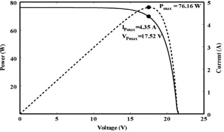
connected in parallel). Fig.15 shows the P-V curve of the 230W system From the P-V characteristics, the power is approximately 230W.
Fig.15. PV curve of solar panel
Fig.16. Panel output power
5.4. Wind Energy Conversion System
84 Fig.17. Simulation of Wind Energy Conversion
System
5.5. Energy Storage System
Energy storage system contains the main parts are battery and energy storage control section. This control section has mainly 3 functions.
1. Check bus voltage level and select the work: buck or boost
2. Provide gate pulse for buck action 3. Provide gate pulse for boost action
Fig.18. Energy storage system
Fig.19. Energy storage system Control
5.6. Multi Input CUK Converter
This CUK converter combines more than one input and provides a single output. Multi Input CUK Converter as shown below
Fig.20. Multi Input Cuk Converter
The current waveform of MI Cuk Converter as shown below
Fig.21. Current Waveform of Multi Input Cuk Converter
Final output as shown below. MI Cuk converter output always in the range of 370 to 390.
Fig.22. Waveform of Bus voltage, DC load voltage and Ac load voltage
6. CONCLUSION
In most of the remote and non-electrified sites, extension of utility grid lines experiences a number of problems such as high capital investment, high lead time, low load factor, poor voltage regulation and frequent power supply interruptions. There is a growing interest in harnessing renewable energy sources since they are naturally available, pollution free and inexhaustible. At present, standalone solar photovoltaic and wind systems have been promoted around the globe on a comparatively larger scale. Its hybrid system has more advantages than individual usage of renewable source.
The principal objective of work is to provide centralized control architecture in input section of hybrid system. For this purpose used a MI Cuk Converter. The Cuk converter has been designed and studied.
85 done using MATLAB and attains the conditions for
meeting a particular load.
REFERENCES
[1] Bounechbaa.H; Bouzida.A; Nabtib.K; Benallab.H,(2014): Comparison of perturb and observe and fuzzy logic in maximum power point tracker for PV systems. The International Conference on Technologies and Materials for Renewable Energy, Energy Procedia 50, PP.677 -684.
[2] Nabulsi.A: Dhaouadi.R: Fuzzy Logic Controller Based Perturb and Observe Maximum Power Point Tracking, College of Engineering American University of Sharjah. [3] Chauhan.A; Saini.R.P: Renewable Energy
Based Power Generation for Stand alone Application: A Review, Alternate Hydro Energy Centre, Indian.
[4] Kumaresh.V; Malhotra.M; Ramakrishna.N; SaravanaPrabu.R,(2014):Literature Review on Solar MPPT Systems, Advance in Electronic and Electric Engineering, ISSN 2231-1297, Volume 4, pp. 285-296.
[5] Muralikrishna.M; Lakshminarayana.V,(2008): Hybrid (Solar and Wind)Energy System For Rural Electrification, Asian Research Publishing Network (ARPN), Vol.3, No.5. [6] Panda.A; Pathak.M.K; Srivastava.S.P,(2011):
Fuzzy Intelligent Controller for the Maximum Power Point Tracking of a Photovoltaic Module at Varying Atmospheric Conditions, Journal of Energy Technologies and Policy, ISSN, pp:2224-3232, Vol.1, No.2.
[7] Pradhan.A; Dr.Ali.S.M; Jena.C; Behera.P, (2013): Design and Simulation of DC-DC Converter Used in Solar Charge Controllers, International Journal of Engineering Inventions, Vol.2, Issue 3, PP: 59-62.