1
Improved Catalytic Convertor for CI
Engine Emission Control System
Ankush Ghodke1, Ganesh Gage2, Amol Madane3, Avinash Shinare4, Naik K.S5.
Department Of Automobile Engineering1,2,3,4, Samarath Group of Institution College of Engineering, Pune 1,2,3,4 Asst. prof. Department Of Automobile Engg5, Samarath Group of Institution College of Engineering. Pune 5
Email: [email protected],[email protected]2, [email protected]3,
[email protected], [email protected]5
Abstract-
The rapidly increasing interest of people towards automobile, moving machinery and off-road appliances have put front some serious (burning) issues. However, all these applications face a common and major challenge which is to meet present and future emission norms. CI engine combustion generate largeamount of NOX. In order to reduce emissions after-treatment of exhaust gas improved catalytic convertor is effective for CI engine but this Exhaust System used in the vehicle has many disadvantages. The regular exhaust systemdoes not meet the demands of euro 6 emission standards and it does not work at high temperatures. So it is necessary to modify the existing regular catalytic convertor. This project relates to the modification of the catalytic convertor so that the problems of the Conventional catalytic convertor can be removed. In this project we are going to modify the ceramic structure of the catalytic by providing it with a wash coat of Cu-Zeolite catalyst. By providing the wash coat of Cu-Zeolite the modified catalytic convertor will reduce the NOx emission at high exhaust temperatures.Keywords
— Catalytic Convertor, NOx reduction at a high temperature, may be meet EURO 6 standard1. INTRODUCTION
A catalytic converter is a device that uses a catalyst to convert pollutants to non-pollutants of combust product in C.I. Engine. The three harmful compounds are:
� Hydrocarbons (formed by the unburned gasoline) � Carbon monoxide (formed by the combustion of gasoline and because of disassociation at high temperature)
� Nitrogen oxides (created when the heat in the engine forces nitrogen in the air to combine with oxygen)
In a catalytic converter, the catalystis coated onto a ceramic honeycomb or ceramic beads that are housed in a muffler-like package attached to the exhaust pipe. The catalyst helps to convert carbon monoxide into carbon dioxide. It converts the hydrocarbons into carbon dioxide and water. It also converts the nitrogen oxides back into nitrogen and oxygen.
2. LITERATURE REVIEW
R.M. Kakwani et al. [1] this research paper shows the comparison between the euro V and euro VI emission standards. From this research papers we understood the need for the modification in the conventional catalytic convertor. Mr Malanga, M.T. et al. [2] in their research paper they summarise about emission standard. The emission standards of Euro 6 have set
2
3. WORKING PRINCIPAL OF
CATALYTIC CONVERTOR
[image:2.612.101.296.390.484.2]A catalytic converter is a device used to reduce the toxicity of emissions from an internal combustion engine. First widely introduced on series-production automobiles in the U.S. market for the 1975 model year to comply with tightening EPA regulations on auto exhaust, catalytic converters are still most commonly used in motor vehicle exhaust system. [9] A catalyst allows chemical conversions to desired products to occur more rapidly and at lower temperatures. Automotive emissions catalytic converters consist of special combinations of precious metals such as platinum, palladium and rhodiumdispersed on high surface area carriers which in turn are coatedonto the walls of ceramic or metallic monolithic structures. In the modern three-way catalytic converter, uncombusted fuel residues are oxidized with oxygen to produce carbon dioxide and water, nitrogen oxides are converted to ubiquitous nitrogen, and toxic carbon monoxide is oxidized with oxygen to carbon dioxide
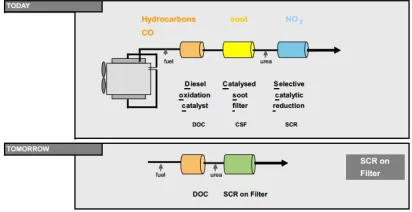
Fig 3. Working Principal of Catalytic Convertor For light duty diesel applications the SCR catalyst consists ofa Cu or Fe containing zeolite. Typical zeolites are Fe- beta and Cu-chabazite. Cu-chabazite exhibits an excellent low temperature activity, a broad temperature window of activity and superior high temperature stability. But these systems cannot meet the emission standards of Euro 6 norms. So new system has been designed called Integrated Catalyst or SCR. This system combines SCR and CSF. This system minimize NOx Percentage. The DOC reduces HC and CO from the exhaust. Soot particles and NOx reduction is done at the SCR on Filter. The SCR and CSF are combined together to form a one part. The porosity of CSF is increased and the layer of SCR is spread on the CSF. This combined structure is effective in reducing the NOx as well as soot particles. SCR on Filter has some different properties as compared to the traditional CSF. The porosity of the SCR on Filter is high as compared to the CSF. This leads to low back pressure in the exhaust after
treatment systems. Due to low back pressure NOx efficiency increases and the catalyst becomes hydrothermally stable even at high temperature.
3.1.Reactions taking place inside catalytic convertor
The reactions which take place in the exhaust after treatment system of a diesel engine for the reduction of NOx are as follows-
4NO + 4NH3 + O2 → 4N2 + 6H2O 2NO2 + 4NH3 + O2→ 3N2 + 6H2O The oxidation of CO takes place as follows- 2CO + O2 → 2CO2
The oxidation of Hydrocarbon takes place in exhaust after treatment systems are as follows-
CxH2x+2 + [(3x+1)/2] O2 → xCO2 + (x+1) H2O This is how the reduction and oxidation of NOx, CO and HC takes place. For light duty diesel applications, the SCR catalyst consists of a cu containing zeolite. Typical zeolites are cu-zeolite. This zeolite exhibits an excellent low temperature as well as high temperature activity. But this system cannot meet the emission standards of Euro 6 norms. So new system has been designed called integrated catalyst. These systems combine SCR and CSF. This system reduces NOx readily.
3.1.Types of catalytic convertor
There are two types of catalytic convertor. They are explained below:
1. Three-way catalytic convertor. 2. Two-way catalytic convertor.
1. Three-way catalytic Convertor
The diesel exhaust system used nowadays has following components.
a) Diesel oxidation catalyst (DOC) b) Catalysed soot filter (COF) c) Selective catalytic reduction (SCR)
a) Diesel oxidation catalyst (DOC)
DOC is a first layer in the exhaust system of the diesel engine. It is responsible for the reduction of the hydrocarbons and the carbon monoxide in the exhaust gas of the diesel vehicle. The primary function of the diesel oxidation catalyst (DOC) is to completely oxidize hydrocarbons and carbon monoxide in the exhaust gas to carbon dioxide and water. In specific applications, the DOC is also expected to partially convert nitrogen oxide (NO) to nitrogen dioxide (NO2).
b) Catalysed soot filter (COF)
COF is the second layer in the diesel vehicle exhaust system. It is responsible for the removal of the particulate matter from the exhaust of the diesel vehicle.
c) Selective catalytic reduction (SCR)
SCR is responsible for the oxidation of the NOx in the exhaust gases of the diesel vehicle.
This emission from the diesel vehicle is according to the EURO 5 emission standard.The new emission standard EURO 6 is set for the light commercial vehicles as well as the heavy duty vehicles. Thenew emission standard EURO 6 has set even lower emission limits as compared to the emission standards of the EURO 5. EURO 6 standard for diesel vehicle has set very low level of NOx. The existing exhaust system of a diesel vehicle is not capable of reducing the emission level to the EURO 6 emission standards. So, it is necessary to design the different exhaust system which will be capable of meeting the emission standards of EURO 6. One solution for this problem is SCROF.
2. Two-way catalytic convertor.
This type of catalytic converter is widely used on dieselengines to reduce hydrocarbon and carbon monoxide emissions. They were also used on gasoline engines in American- and Canadian-market automobiles until 1981. Because of their inability to control oxides of nitrogen, they were superseded by three-way converters.
4. PROBLEMS WITH CONVENTIONAL
CATALYTIC CONVERTOR
1. High weight to volume ratio:
The conventional catalytic convertor used in the diesel engine has very high weight to volume ratio. This increases the overall weight of the vehicle. Due to the increase in the weight of the vehicle the use of the fuel increases and the vehicle gives low fuel economy.
2. Low NOx reduction emission in high temperature: The conventional catalytic convertors that are used in the diesel engine have very low NOx reduction at high temperatures. The catalyst like platinum, palladium used in the catalytic convertor has low working range.
3. Does not meet with EURO 6 norms:
Euro 6 norms have been revived and these norms have reduced the NOx emission standards. The conventional catalytic convertors does not meet the euro 6 norms. So, there is need to reduce the emission of NOx in order to meet those euro 6 emission standards.
4. High back-pressure:
Exhaust backpressure can cause a variety of problems. A plugged catalytic converter can strangle engine breathing andcause a big drop in engine performance and fuel economy. And if the converter plugs up completely, it can make the engine stall. The same thing can happen if a muffler, resonator or double walled exhaust pipe collapses internally. Anything that restricts exhaust flow will create excessive backpressure in the exhaust system.
5. MODIFICATION IN CATALYTIC
CONVERTOR
[image:3.612.315.521.525.631.2]The solution to above all problems is to modify theconventional catalytic convertor. Modifying the catalytic convertor may solve the problems and the euro 6 emission norms will be satisfied. We are going to combine the soot filter and selective catalytic reduction layers of monolith structure with new prepared catalyst Cu-zeolite.
4 substrate of the CSF. This integrated catalyst is in the
following called SCR on Filter or just SCROF. SCROF stands for Selective catalytic reduction on filter. SCROF is a new exhaust system which can be used for the diesel engine to reduce the NOx levels to a desired level to meet the emission standards of EURO 6. This system combines the two layers of a traditional diesel exhaust system. It combines catalyzed soot filter and selective catalytic reduction in order to decrease the emission level.
5.1.
Selection of catalytic convertorThe catalytic convertor is selected on the basis of the engine. The catalytic convertor selected is of TATA indica vehicle.
5.2.Ceramic monolith structure:
The ceramic monolith structure is a very important part of the catalytic convertor. The ceramic structure has a wash coat on its surface for reduction of the exhaust gases.
A ceramic honeycomb monolith shown in fig has large number of parallel and straight open channels (cells) for flow of exhaust gases. The flow through this is laminar. The ceramic material commonly used is porous cordierite (2MgO.2Al2O3.5SiO2). The cordierite is a low-thermal expansion ceramic
5.3.Skeleton of catalytic convertor:
Now day’s catalytic convertors are used for exhaust emission control in SI and CI engine vehicles. The standard dimension of catalytic convertor is taken from cars Boucher. The preparation of skeletal catalysts is considered, with particular reference to the preparation of skeletal nickel and skeletal copper.
Fig 5.3. Skeleton of catalytic convertor 3.2.Convertor housing:
The ceramic monolith structure is mounted in high quality corrosion steel casing. A mat made of ceramic material or wire mesh surrounds the ceramic monolith to hold it tightly inside the casing. The mat protects the ceramic monolith against mechanical impact and vibration and also acts as the insulation. The ceramic mat is made of aluminum silicate that expands as the temperature rises. As the temperature rises gas bubbles are formed inside the mat and it ensures proper sealing to prevent any bypass of the exhaust gases as well as
[image:4.612.317.521.150.220.2]tight backing of the ceramic monolith.
Fig 5.4. Monolith structure inside the housing.
3.3.Catalyst (cu-zeolite)
There are several types of catalyst to promote the desired reaction to convert the pollutants to harmless gases. These includes oxides of base metals and noble metal such cu-zeolite, cu-zeolite etc.
3.4.Chemicals used for preparation of Cu zeolite:
The chemicals used for preparation of Cu-zeolite are: 1. Zeolite powder (ZSM 5)
2. Cupric acetate hydrate
The chemical of cu-zeolite was prepared at chemical laboratory.
3.5.Selection of engine
We selected the engine from IC engine lab for our testing purpose. Selected engine is TATA Indica multi cylinder diesel engine.
Engine specification:
4- Cylinder, 4-stroke diesel engine TATA Indica, capacity- 1405cc Power- 44.7 kW@5000 rpm.
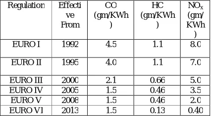
[image:4.612.314.528.542.659.2]European Emission Standards:
Table 1 European Emission Standards Regulation Effecti
ve From
CO (gm/KWh
)
HC (gm/KWh
)
NOx
(gm/ KWh )
EURO I 1992 4.5 1.1 8.0
EURO II 1995 4.0 1.1 7.0
EURO III 2000 2.1 0.66 5.0
EURO IV 2005 1.5 0.46 3.5
EURO V 2008 1.5 0.46 2.0
5 4. CONCLUSIONS
The improved catalytic is testunder variable load and compare withwithout catalytic convertor system on same engine for its performance and emission parameter of CI engine.
As we combining the soot filter and selective catalytic convertor, it will satisfy our main objective i.e. low weight-volume ratio and High NOx reduction emission in high temperature.
Modifying the catalytic convertor may solve the problems and the euro 6 emission norms will be satisfied.
ACKNOWLEDGMENT
The authors wish to acknowledge the support rendered by Samarth Group of Institution College of Engineering, Belhe in preparation of this manuscript.
REFERENCES
[1] R. M. Kakwani, K.Voss, J. Patchett & K.Grimston Engelhard “Combined Catalyzed Soot Filter and SCR Catalyst System for Diesel Engine Emission Reduction”.6th diesel engine emission reduction (DEER) workshop, August 20, 2000 San Diego, California.
[2] Malanga, M.T., Allen, M.P., Das, N.S., Kotnis, A., Mikulic, I., Vosejpka, P.C., Majkowski, S.F. “Future Trends for DPF....SCR on-Filter (SCRF)”. DEER Conference October 2012 - Detroit, Michigan
[3] Dieter Rauch, David Kubinski Dieter Raucha, Ulrich Simonc, Ralf Moosa “Detection of the Ammonia loading of a Cu Chabazite SCR catalyst y a radio frequency based method”. Department of Functional Material, University of Bayreuth, 30 94440 Bayreuth, Germany. 17 August 2014.
[4] Hans-Dieter Harder, Marc Braggers, Rolf Brück. “Future SCR NOX Aftertreatment Systems for Euro 6
[5] Michael Rice, Jan Kramer, Klaus Mueller-Haas, Raimund Mueller. “Innovative Substrate Technology for High Performance Heavy Duty Truck SCR Catalyst Systems”. 2007 SAE International.
[6] Dr. R. Samuel Boors’, Dr. Martin Diatreme, Dr. Kenneth Voss, Dr. Susanne Stiebels, Dr. Claudia Wendt, Dr. TorstenNeubauer, “ Two in One: SCR on Filter”. BASF Catalysts Germany GmbH; Freundallee 23, 30173 Hannover. [7] Yisun Cheng, Christine Lambert, Do Heui Kim,
Ja Hun Kwak, Charles H.F. Peden, “Investigation of Sulfur Deactivation on Cu/Zeolite SCR Catalysts in Diesel Application”. August 4, 2009 2009 DEER
Conference
[8] Dr. Klaus Harth “compact catalytic convertor”, BASF Corporation in Ludwigshafen (Germany). [9] Pundir, B. P., “Engine Emissions – Pollutant