Optofluidic Dye Lasers
Thesis by
Zhenyu Li
In Partial Fulfillment of the Requirements for the Degree of
Doctor of Philosophy
California Institute of Technology Pasadena, California
2007
c
Acknowledgements
First, I would like to express my sincere gratitude to my advisor, Professor Demetri Psaltis, for his support and guidance throughout my graduate studies at Caltech. I’ll be forever indebted to him for offering me the opportunity to pursue my PhD degree at the same school as my wife, not to mention it’s Caltech. His contagious enthusiasm, keen intuition and objective attitude have been a constant source of inspiration. As one of his last students at Caltech, I wish him all the good luck for his new challenging position at EPFL, and hope always to have the chance to work with him in the future.
I would also like to thank Professor Axel Scherer, Zhaoyu Zhang, Teresa Emery and Yan Chen for the fruitful collaborations that led to much of the work presented here. Over the years, I have learned a lot from my collaborators at various stages of my research, in particular, Prof. Changhuei Yang of Caltech; Prof. George Barbastathis and Dr. Kehan Tian of MIT; Dr. Annmarie Eldering, Dr. Gregory Bearman and William Johnson of JPL; Dr. Harvey Kasdan of Iris Diagnostics; Dr. Wenhai Liu and Dr. Christophe Moser of Ondax.
most educational and memorable experiences of my life. While by no means an exhaustive list, I would especially like to thank: Xiaoli Feng, Vijay Gupta, Rizal Hariadi, Xin Heng, Cheng Jin, Zhipu Jin, Wei Liang, Xin Liu, Bumki Min, Eric Ostby, Troy Rockwood, Kevin Tang, Jiantao Wang, Lan Yang, Qiang Yang, Hualin Ye, Zhengrong Wang and David Wei.
I also want to thank my parents-in-law, Guobin Li and Guoqing Sun, for taking good care of my daughter so that my wife and I could concentrate on work during our last year at graduate school.
I want to thank my parents and my sister, whose unconditional love, understanding and support have carried me through the unimaginably long educational path. It was their influence that made me decide long ago I would only choose a career I like.
Abstract
Optofluidic dye lasers refer to a class of liquid dye lasers, usually on a microfabricated device, in which the adaptive nature of the liquid gain medium allows the dynamical con-trol of the laser properties. Miniaturizing liquid dye lasers onto a microfluidic device not only results in compact, easy-to-maintain and safe dye laser systems, but also provides un-precedented optical performances such as precise spatial mode control, low threshold, and automatic fluidic tuning. Equally important, such on-chip liquid laser sources represent an important component for “lab-on-a-chip” systems.
Contents
Acknowledgements v
Abstract vii
1 Introduction 1
1.1 Motivations for Building On-chip Liquid Dye Lasers . . . 1
1.2 Thesis Organization . . . 3
2 Background and Related Work 5 2.1 Ingredients of Optofluidic Dye Lasers . . . 5
2.1.1 Liquid Dye Lasers . . . 5
2.1.1.1 Photophysical Properties of Organic Dye Molecules . . . 6
2.1.1.2 Rate Equations . . . 10
2.1.1.3 Laser Threshold . . . 12
2.1.2 Microfluidics and Lab-on-a-chip Systems . . . 13
2.1.3 Optofluidic Integration and Adaptation . . . 15
2.2 Related Work . . . 16
2.2.1 Pre-Microfludics Era Microscopic Liquid Dye Lasers . . . 16
2.2.1.1 Microcavity Dye Lasers . . . 17
2.2.1.2 Waveguide Dye Lasers . . . 23
2.2.2 Other Groups’ Work on Optofluidic Dye Lasers . . . 24
3.1.1 Theory and Simulations of DFB Structures . . . 28
4 Mechanically Tunable Optofluidic DFB Dye Lasers and Integrated DFB Dye Laser Arrays 47
4.2.2 Simultaneous Operation of Thirteen DFB Lasers On a Single Chip . 58 4.3 Summary . . . 60
5 Microfluidic Tuning of Optofluidic DFB Dye Lasers 61 5.1 Monolithic Integration with PDMS based Microfluidic Tuning Circuits . . . 61
6 Optofluidic Microring Dye Lasers 73
7 Evanescent Gain Optofluidic Dye Lasers 83 7.1 Liquid-Cladding DFB Dye Lasers Based on Evanescent Gain . . . 83
8 Towards an LED Pumped On-Chip Dye Laser Using a Surface Emitting Circular-Grating Resonator 95 8.1 Dye Doped Solid State Polymer Lasers . . . 95
8.2 Circular Grating Resonator Design and Fabrication . . . 97
8.2.1 Circular Grating Distributed Feedback Resonators . . . 97
A.2 Master Mold Fabrication . . . 108
A.2.1 Laser Mold Fabrication . . . 108
A.2.2 Microfluidic Circuits Mold Fabrication . . . 109
A.3 PDMS Device Fabrication . . . 109
A.3.1 Two-Layer Devices . . . 109
A.3.2 Three-Layer Devices with Push-Up Valves . . . 110
List of Figures
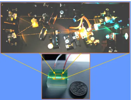
1.1 Miniaturization of liquid dye lasers on a microfluidic chip. . . 2
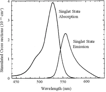
2.1 Stimulated singlet state absorption and emission cross sections for Rho-damine 6G in ethanol. . . 7
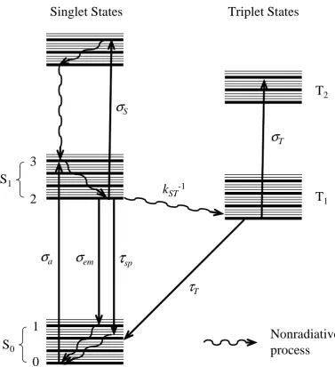
2.2 Typical energy levels of an organic dye molecule. Each transition is labeled by its corresponding cross section or lifetime. . . 8
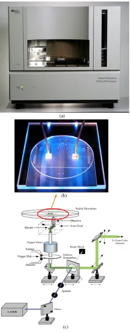
2.3 Conventional fluoresence based Sanger DNA sequencer and the “lab-on-a-chip” version. (a) Applied Biosystems 3760xl DNA Analyzer. (b) A mi-crofabricated bioprocessor integrating all three Sanger sequencing steps. (c) The bulk optical setup for fluorescence excitation and detection used together with the microfabricated device shown in (b). . . 14
2.5 a. Cylindrical evanescent gain microcavity dye laser. b. Schematics and mi-croscope images of (1) radial mode lasing and (2) WGM lasing. c. Typical spectra of WGM lasing with the central optical fiber inserted. Inset: typi-cal single shot spectra from the radial mode lasing without the central fiber. Reprinted from [2]. . . 20
2.6 a. Schematic of a Fabry-Perot microcavity dye laser. b. Light output vs. input curves. For short cavity lasers, the laser threshold became fuzzy while a clear threshold appeared for the d =500 cavity. c. Spontaneous and laser emission spectra. For the d = /2 cavity, the two spectra were very simi-lar. However for the d= 500 cavity, a dramatic spectral narrowing occurred above threshold. Reprinted from [3]. . . 22
3.1 Transmission matrices in Rouard’s method for simulating the spectra of a DFB structure. (a). Dielectric interface. (b). Propagation over a distance with no discontinuities. (c). Bragg grating. . . 30
3.2 Simulated transmittance spectrum for a DFB structure with parameters:n0 =
n3 =1.406,n1= 1.407,n2 =1.406,d1 =d2 = 1.5µm, and the grating length
L=8mm. . . 32
3.3 Simulated transmittance spectrum for a λ/4-shifted DFB structure with the same parameters as those in Figure 3.2 except that the central slab has been increased to twice its original length dde f ect = 3µm to form a defect. The
central defect gives rise to a transmission resonance inside the bandgap. . . . 33
3.4 Comparison of a first order DFB and a higher order DFB structure. . . 34
3.5 Schematic diagram of a monolithic optofluidic DFB dye laser chip. . . 36
3.6 Simulated reflectivity spectrum of a 15 phase shifted 15th order DFB struc-ture. The curve spanning from 550nm to 650nm is the gain spectrum of Rhodamine 6G. The inset shows the enlarged plot the 15th resonance at 563nm. 38
3.8 Optical micrograph of a microfluidic channel with an embedded phase shifted 15th order DFB structure on a PDMS chip. The grating period is 3µm. The channel width is 5µm. The central larger PDMS post introduces a 15π/2 phase shift. The upper left inset shows the picture of an actual optofluidic dye laser chip. . . 41
3.9 Characterization setup for the optofluidic dye lasers. . . 42
3.10 Single mode optofluidic DFB dye laser spectrum. The measured linewidth is 0.21nm. . . 43
3.11 The light-out v.s. light-in curve. The threshold pump fluence is∼0.8mJ/cm2. 44
4.1 Schematic diagram of a mechanically tunable optofluidic DFB dye laser chip. The upper inset shows an actual monolithic PDMS laser chip. The lower inset is an optical micrograph of the central phase-shifted region of the laser cavity. A Bragg grating with 3080nm period is embedded in a 3 m wide microfluidic channel. The channel height is 2 m. The size of the PDMS posts is about 1.28 m 1.8 m measured from the optical micrograph. The central larger PDMS post introduces an effective/2 phase shift to ensure single wavelength lasing. The movement of the translation stage deforms the chip which causes the grating period to change. . . 49
4.2 Two color lasing from the same DFB cavity. Upper: Simulated reflectivity spectrum of aπ/2 phase shifted higher order DFB structure. The parameters used are given in the main text. Also shown are the normalized measured fluorescence spectra of Rh6G and Rh101 solutions used in the lasing ex-periment. Lower: Orange and red lasing spectra were observed when two different dye solutions Rh6G and Rh101 were subsequently introduced into the cavity. . . 51
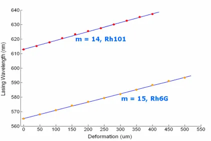
4.4 Lasing wavelength versus the measured chip deformation. The points are the experimental data and the curve is the linear fit. The achieved single mode tuning range for Rh6G is from 565nm to 594nm and is from 613nm to 638nm for Rh101. . . 54
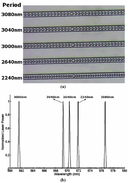
4.5 (a): Optical micrograph of an integrated array of five optofluidic DFB dye lasers. The grating period of each laser is given on the left. (b): normalized laser output of the array using Rh6G dye solution as the gain medium. . . 56
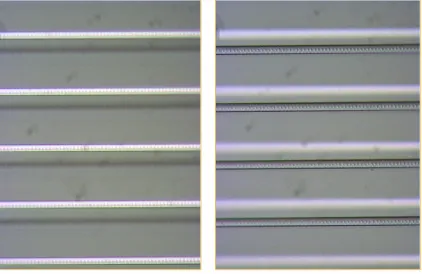
4.6 Vertical stacking of optofluidic DFB laser arrays using multi-layer soft lithog-raphy. Left: upper laser array is in focus. Right: bottom laser array is in focus. 57
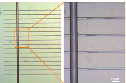
4.7 Optical micrograph of an array of 16 DFB dye laser cavities connected to the input liquid channel in PDMS. The lasing wavelengths are designed to operate from 565nm to 640nm with 5nm spacing. The waveguide dimen-sions are 4µm wide and 2µm high. The PDMS posts are 2µm wide and half grating-period long. . . 58
4.8 Simultaneous lasing spectrum of the 16 DFB laser array. 13 lasers oper-ated above the thresholds. The wavelength spacing was∼4.94nm due to the PDMS shrinkage. The middle 6 laser lines saturated the detector. . . 59
5.1 PDMS micro mechanical valve and peristaltic pump (push-down version). Left: operation of the valve. Right: operation of the peristaltic pump. Source: www.fluidigm.com . . . 62
5.3 Lasing spectrum of the 15th order optofluidic DFB dye laser with high index contrast between the liquid core and the PDMS cladding. The waveguide dimensions are 2µm by 5µm. The grating period is 3µm. The refractive index of the Rh6G dye solution is 1.478 in DMSO. More than 20 lasing modes were observed. The inset shows four simulated TE-like transverse mode profiles. . . 66
5.4 Fluidic tuning of a 5th order DFB dye laser with waveguide core dimensions 250nm by 880nm. The inset shows a scanning electron micrograph of the silicon mold. The grating period is 1µm. . . 67
5.5 Optimum waveguide dimensions for maximum single mode wavelength tun-ing range by fluidic index tuntun-ing. The maximum stun-ingle mode tuntun-ing range of∼15nm is achieved with core dimensions 880nm by 880nm for core index change from 1.406 to 1.478. . . 69
5.6 Si mold for the 1st-order DFB optofluidic dye laser fabricated by Ebeam lithography (EBL) and reactive ion etching (RIE). . . 70
6.1 Optofluidic microring dye laser. Left: a liquid core microring resonator ini-tially used as a microfluidic mixer. The ring radius is 1 mm and the channel width is 80 m. The shaded area inside the dashed box is the area that is under pump light. Right: a typical lasing spectrum of the ring dye laser. . . 74
6.2 Schematic diagram of an optofluidic microring dye laser chip. . . 75
6.3 (a) Optical micrograph of an optofluidic microring resonator in PDMS. The waveguide dimensions are 3µm wide and 2µm high. The ring diameter is 200µm. (b) A typical measured lasing spectrum of an optofluidic microring dye laser with a 200µm diameter ring. . . 77
6.4 Light-in v.s. Light-out curve. The laser threshold is 9.2nJ. . . 78
6.6 Single mode optofluidic microring dye laser using Vernier effect. The laser cavity is a distributed feedback coupled microring structure between two bus waveguides. The two ring radii are R1= 5µm and R1= 5.4µm . The ring separation is chosen to be π(R1+R2)/2 to simplify the photonic band structure. The central larger waveguide separation forms a defect mode in the band gap. The transverse dimentions of all the waveguides are 2µm by
2µm . . . 80
7.1 Schematic cross section of a liquid-cladding waveguide structure. . . 84
7.2 Fundamental transverse mode profile of the liquid-cladding waveguide sim-ulated by FEM (Comsol FEMLAB 3.2). The effective index is 1.643 at 580nm. . . 85
7.3 Simulated longitudinal mode spectrum of the liquid-cladding DFB structure. The effective index 1.643 used in the simulation is that of the fundamental transverse mode. . . 86
7.4 A single mode sub-wavelength scale waveguide with a large overlapping factor between the mode and the upper cladding. . . 87
7.5 Fabrication of SU8 DFB waveguide cores on glass slides and silicon dioxide coated Si wafers. (a). SU8 waveguide detached from the glass slide substrate (b). High quality SU8 waveguide on SiO2coated Si wafer. . . 89
7.6 Optical micrograph of an liquid-cladding evanescent gain DFB dye laser. The SU8 DFB waveguide core is under a 100µm wide PDMS microfluidic channel. The channel height is 10µm. The inset shows an actual chip on a 2 inch wafer. . . 90
7.7 (a) Emission spectrum of a PDMS channel filled with Rh6G dye solution, without the SU8 DFB waveguide core. (b) Lasing spectrum with the SU8 DFB waveguide core. . . 91
8.1 General design of a circular grating distributed feedback structure. . . 97
8.2 Fabrication process flow of circular grating polymer dye lasers. . . 99
8.4 Nanoimprinted circular grating DFB dye laser spectrum. The measured linewidth is 0.18nm. Left inset: The output power vs. the absorbed pump energy curve. The threshold fluence is 1.31nJ/mm2. Right inset: Polymer laser chip excited by Nd:YAG 532nm laser pulse. . . 101
List of Tables
2.1 Typical values of the photophysical parameters for Rhodamine 6G (pump wavelengthλP=532nm, laser wavelengthλL=580nm) . . . 11
Chapter 1
Introduction
This thesis presents a new class of liquid dye lasers, which we call optofluidic dye lasers. In these microfabricated laser systems, the liquid dye solution, besides providing the optical gain, plays a crucial role in determining the optical properties of the laser light such as the lasing wavelength, the spatial mode and the tunability. The emergence of optofluidic dye lasers is largely enabled by the recent advances in microfabrication and microfluidics technologies [4][5]. With micromachining and soft lithography techniques, micron-scale fluidic channels can now be routinely made in optically transparent glasses, polymers and silicone elastomer materials. This enables the fabrication of liquid core or liquid cladding integrated optical components onto the same device as the microfluidic circuits. Highly automated on-chip fluidic manipulation and large scale integration also became a reality after the development of silicone elastomer based micro mechanical valves and pumps [5][6][7].
1.1 Motivations for Building On-chip Liquid Dye Lasers
Figure 1.1: Miniaturization of liquid dye lasers on a microfluidic chip.
For example, in the dye lasers discussed in this thesis, the integrated optical components and highly automated microfluidic circuits replaced their bulk counterparts, and resulted in centimeter-sized devices as shown in Figure 1.1. In addition, the extremely small consump-tion of dye soluconsump-tions in microfabricated devices not only reduces the cost, but, combined with the sealed structure, significantly improves the safety and ease of use of dye laser systems.
Third and probably the most important feature of optofluidic dye lasers is their ability to integrate with other optical and microfluidic functions to build complete ”lab-on-a-chip” systems. This represents an important step towards fully functional and portable devices for medical diagnostics, environmental monitoring, forensic and bioterrorism detection [10].
1.2 Thesis Organization
Chapter 2
Background and Related Work
Three ingredients are indispensable for the development of optofluidic dye lasers: con-ventional liquid dye lasers, microfluidics, and optofluidic integration and adaptation. There-fore, in this chapter, we provide the background knowledge on these three topics that are important for the discussions in later chapters. Section 2.1.1 briefly reviews the gen-eral properties of liquid dye lasers including the photophysical properties of organic dye molecules, a rate equation model for dye lasers and a simple pump threshold analysis. Section 2.1.2 discusses the state of the art microfluidics and “lab-on-a-chip” technologies. Particular attention is paid to the lack of optical functions in most demonstrated ”lab-on-a-chip” systems. Section 2.1.3 introduces the general idea of optofluidics and its potential impact on both adaptive optics and ”lab-on-a-chip” systems. We also present the previous work related to this thesis in Section 2.2, which includes both pre-microfluidics era micro-scopic liquid dye lasers (Section 2.2.1) and on-chip microfluidic dye lasers demonstrated by other groups (Section 2.2.2).
2.1 Ingredients of Optofluidic Dye Lasers
2.1.1 Liquid Dye Lasers
make dye lasers an ideal coherent light source for spectroscopy [11]. The unique features of dye lasers are directly linked to the molecular structures and the photophysical properties of organic dye molecules. Therefore, we will start with the discussion of the properties of laser dyes. Based on these properties, we will build a rate equation model for dye lasers and use it to study the threshold for the laser action. No attempt is made to give a comprehensive review on conventional dye lasers since a number of excellent articles ([12], [13], [14], [15], [16], [17]) and books ([11], [18]) are already available. Another very useful resource is a collection of original papers on dye lasers which has been published in the SPIE Milestone Series [19]. Textbooks on semiconductor lasers [20] and integrated optics [21][22] are also good references for the study of optofluidic dye lasers due to their similar sizes, structures and gain properties.
2.1.1.1 Photophysical Properties of Organic Dye Molecules
Laser dyes are complex organic molecules containing long chains of conjugated double bonds (i.e. alternating single and double carbon bonds, =C-C=C-). The large molecular size and the relatively free moving π-electrons in the conjugated double bonds give rise to the large dipole moments of dye molecules (or equivalently, oscillator strengths). The complex molecular structure also leads to many vibrational and rotational levels within a single electronic state. Therefore, laser dyes often have strong and wide absorption bands in the UV and visible region as shown in Figure 2.1 [23]. The emission spectra of dye molecules are Stokes-shifted to longer wavelength and form almost mirror images of the absorption bands due to the so-called Frank-Condon principle [24]. This is a rather fortu-nate feature because the laser emission will generally not be strongly absorbed by the dye itself. In the following, we will briefly discuss the energy levels and the transition processes involved in the laser operation, with a special focus on the effects of the dark triplet states. For more complete discussions of the photophysical and photochemical properties of laser dyes including the environmental effects, the readers are referred to the reference [11].
Figure 2.2 shows the typical energy levels of a dye molecule. S0and S1are the ground
and the first excited singlet electronic states. T1 and T2 are the first and second excited
σ
emτ
Tk
ST-1Triplet States
Singlet States
S
0S
1T
1T
2Nonradiative
process
0
1
2
3
σ
aτ
spσ
Tσ
Sof the remaining molecule and the total spin quantum number is S = 0, whereas in a triplet state the two spins are parallel and S = 1. Therefore singlet-singlet and triplet-triplet transitions are allowed, while singlet-triplet-triplet transitions are forbidden because of the selection rule ∆S = 0. As mentioned before, each electronic state is further split into many vibrational and rotational sublevels due to the complex dye molecular structure. In addition, the effective homogenous line-broadening mechanism due to the collisions with solvent molecules further smears these sublevels into unresolved overlapping bands. The homogenous broadened spectra of dye molecules enable very efficient channeling of the pump energy into narrow band laser emissions [17].
It is important to realize that the dye laser is a classical 4-level system (if neglecting the triplet states for the moment) where the 4 energy levels are marked 0 to 3 in Figure 2.2. Under optical excitation, dye molecules are pumped from the bottom of the ground state S0 (ground level 0) to some vibrational-rotational sublevels in the first singlet state
S1 (intermediate pump level 3). The dye molecules in level 3 quickly relax to the bottom
of S1 (upper laser level 2). This nonradiative decay process happens on the time scale of
a few picoseconds or less. The energy lost in this process contributes to the heating of the solvent. From the upper laser level 2, dye molecules can undergo eitherspontaneous emissionorstimulated emissionto some vibrational-rotational sublevels in S0(lower laser
level 1). The nonradiative decay time from the lower laser level 1 to the ground level 0 is also a few picoseconds. There are also some absorptions from the first excited singlet state S1to higher singlet states, but this effect is normally small and the nonradiative relaxation
time from higher singlet states back to S1 is also on the order of picosecond. Due to the
extremely fast nonradiative decay processes, the populations of the lower laser level n1
and the intermediate pump leveln3 are negligibly small. Therefore, dye lasers can reach
threshold at very small population inversions, with typical upper laser level populationn2/n
of only 0.01 or less [17], wherenis the total dye population. However, because of the short upper-state lifetimes (a few nanoseconds, mainly due to spontaneous emission), dye lasers still need high pump intensities to reach threshold (see equation (2.7) in section 2.1.1.2).
nonradiative intersystem crossing to the dark triplet state T1. As mentioned before, this
process requires a spin flip of the excited electron and thus is spin-forbidden. This is the reason that intersystem cross has a relative slow transition rate (1/kS T ∼ 100ns) and the
triplet state lifetime is long (τT ∼ 100ns). The metastable triplet state has two detrimental
effects on laser oscillation. First, the long lived triplet state T1 traps the dye molecules and
decreases the available population inversion. Second, the absorption from the first triplet state T1to the second triplet state T2tends to overlap with the laser emission and produces
extra losses at the laser wavelength. Therefore, short pump pulses, fast circulation of dye solutions and triplet state quenchers are often used to minimize the triplet state influences in different types of dye lasers.
2.1.1.2 Rate Equations
Rate equations describe the time evolution of the energy level populations and the laser cavity mode. Although they don’t account for the coherent properties of the laser light, they are very useful for the estimations of the laser threshold and output power.
For dye lasers, three rate equations are needed for describing the laser cavity mode pho-ton fluxφ(= IL/hνL), the singlet state population densityn2and the triplet state population
densitynT.
whereσi’s are the stimulated transition cross sections at the laser wavelengthλL, n0is the
ground state population density, γ is the single pass cavity loss (equals−ln(R1R2)/2+ γi
for Fabry-Perot cavities with internal lossγi),Lis the length of the gain region andcis the
speed of light.
First excited singlet staten2:
dn2
dt = RP+[n0σa(λL)−n2σem(λL)]φ−n1σT(λL)−n2kS T − n2
τsp
wherekS Tis the intersystem crossing rate,τspis the spontaneous emission lifetime, and the
pump rate per unit volumeRPis given by
RP =
n0σa(λP)IP
hνP
(2.3)
where IP is the pump intensity, λP and νP are the pump light wavelength and frequency
respectively, andhis Planck’s constant.
First excited triplet statenT:
dnT
dt = n2kS T − nT
τT
(2.4)
whereτT is the triplet state lifetime.
Finally, the conservation of molecules requires
n=n0+n2+nT (2.5)
wherenis the total concentration of dye molecules. The typical values of the photophysical parameters needed in the rate equations are listed in Table 2.1 for the most common laser dye, Rhodamine 6G [18].
Table 2.1: Typical values of the photophysical parameters for Rhodamine 6G (pump wave-lengthλP =532nm, laser wavelengthλL=580nm)
Parameter Value
Absorption cross section at the pump wavelengthσa(λP)(cm2) 3.8×10⁻¹⁶
Absorption cross section at the laser wavelengthσa(λL)(cm2) 1×10⁻¹⁹
Stimulated emission cross section at the laser wavelengthσem(λL)(cm2) 1.2×10⁻¹⁶
Triplet state absorption cross section at the laser wavelengthσT(λL)(cm2) 1×10⁻¹⁷
Spontaneous emission lifetimeτsp(ns) 5
Intersystem crossing time 1/kS T) (ns) 100
Intersystem crossing time 1/kS T (ns) 100†
†Vary from 10−7to 10−3seconds depending on the solvent and the presence or absence of
2.1.1.3 Laser Threshold
Our analysis of the pump threshold is similar to those given in [24] and [25]. A more thorough treatment can be found in [23]. In general, the laser threshold can be obtained by numerically solving the rate equations. However, as shown in the following, under certain approximations, analytic expressions can be derived to give reasonable estimates.
Pulsed Operation
In pulsed operation with pump pulse duration shorter than the intersystem crossing time 1/kS T, we can neglect the triplet state effects all together. This is because with very short
pump pulses, the whole cycle of excitation and laser emission within the set of singlet states can be completed before a significant triplet state population buildup occurs. Also we assume the self absorption at the laser wavelength is small. In this case, the threshold population inversion density is determined only by the cavity loss [24]
n2th=
γ σem(λL)L
(2.6)
Therefore, the threshold pump intensity needed to achieve this upper state population is
I2th =n2thhνPd/τsp=
γhνPd
σem(λL)τspL
(2.7)
wheredis the penetration depth of the pump light into the dye solution, given by 1/n0σa(λP).
For simplicity we don’t consider the spatial dependence of the pump rate and the specific pumping geometry. The readers can find the more accurate treatments in most laser text-books [24][26].
Continuous Wave (CW) Operation
In CW operation, the triplet state population nT at equilibrium (steady state) can be
obtained from equation (2.4),
The threshold gain equals the total loss and, from equation (2.1), is given by
gth=n2σem =n0σa+nTσT +γ/L (2.9)
where all the cross sections are evaluated at the laser wavelength. With the help of the population conservation relation (2.5), we get the threshold population inversion
n2th=
nσa+γ/L
σem+σa(1+kS TτT)−σTkS TτT
(2.10)
In all practical CW dye lasers, the excited dye molecules are quickly removed from the excitation region and a triplet state quencher is often added to the solution. These two methods effectively reduce the triplet state lifetime by several orders of magnitude. Again for many efficient laser dyes, the self absorption is negligibly small. Consequently, we can set kS TτT ∼ 0 and σa ∼ 0 in equation (2.10), which reduces it to the same expression
as equation (2.6). Therefore, we can use expression (2.7) to roughly estimate the pump threshold for both pulsed and CW dye lasers. For typical valuesσem =1×10⁻¹⁶cm2, τsp =
5ns,d = 1mm,L = 10mm, γ = 0.01, νP = 5.6×10¹⁴Hz (530nm), the calculated threshold
pump intensity is approximately 740W/cm2, the corresponding population inversion n 2 is
about 1×1016cm−3and the threshold gain coefficient is about 1cm−1. In practical systems,
the threshold intensity is usually much higher, about 50kW/cm2, due to the triplet state
effects, self absorption, thermal distortions and higher cavity losses.
2.1.2 Microfluidics and Lab-on-a-chip Systems
instruction books has profound impacts on biology and medicine [30][31]. However the real power of DNA sequencing comes from comparative genomics and personalized ge-nomics by comparing genomes across species and individual genome sequences, which requires much faster and cheaper sequencing techniques than the current ones. Imagine if we can sequence and compare 100 individual genomes at a low cost and in a short period, we will have much better chances of finding out the molecular origins of many diseases such as cancers, Alzheimer’s disease and autism. Today’s DNA sequencers (for example, the ABI 3730xl DNA Analyzer, Figure 2.3-(a)) cost half a million dollars each and are way too slow for this purpose. One way to achieve low cost and high throughput is through miniaturization. Over the past few years, Richard Mathies’ group at UC Berkeley has made remarkable progress along this direction. In one of their recent demonstrations as shown in Figure 2.3-(b), a nanoliter-scale bioprocessor integrating all three Sanger sequencing steps: thermal cycling, sample purificaiton and capillary electropherisis, was fabricated on a glass/PDMS hybrid device [32]. The same group has also demonstrated high through-put operation with a 96-line array electrophoresis device on a single glass substrate [33]. However, the nice looking microfabricated devices are not the whole picture. The com-plete setup, as shown in Figure 2.3-(c), still occupies a table and includes a visible laser source, relay optics and filters, four photomultiplier tubes, data acquisition electronics and a computer. In fact, this represents a major problem for almost all the demonstrated “lab-on-a-chip” systems so far. Much effort is still needed to achieve the seamless integration of optical and electronic functions with microfluidics on the same device. “Lab-on-a-chip” systems must become compact stand-alone and easy-to-use devices before nonexperts such as biologists, chemists, clinicians and police officers can use them.
2.1.3 Optofluidic Integration and Adaptation
dyes, quantum dots and dielectric/metallic nanoparticles, and the ease of forming optically smooth interfaces by surface tension. Combining microfluidics and liquid optical mate-rials, optofluidics offers a new way of implementing integrated optical systems, which is intrinsically adaptive and reconfigurable. One important example of such systems is the optofluidic dye lasers, in which the adaptive nature of the liquid gain medium and the com-bination with microfluidic liquid handing can enable unprecedented optical performances and high degree of system integration. Comprehensive discussions of the recent emergence of optofluidics and classifications of optofluidic devices can be found in [8] and [34].
2.2 Related Work
2.2.1 Pre-Microfludics Era Microscopic Liquid Dye Lasers
The small dimensions of the optofluidic dye lasers are generally achieved using micro-fabrication techniques. However, there existed micron-sized liquid dye lasers long before the advent of microfluidics which also satisfy our definition of optofluidic dye lasers, such as microdroplet dye lasers [35], microcapillary dye lasers [36], and evanescent gain mi-crosphere [2] and fiber lasers [37] immersed in dye solutions. These pre-microfluidics era micron-scale dye lasers are also amenable to microfluidic implementations and have potentially interesting applications.
each category and discuss their possible implementations using microfluidics technology.
2.2.1.1 Microcavity Dye Lasers
Optical microcavities are resonant structures that confine light in small volumes. A ma-jor application of microcavities is to build compact and efficient laser sources. Liquid dye solutions are among the first material systems used to study the laser action and other op-tical processes in microcavities [38][39]. First, we will discuss dye laser actions in surface tension induced microdroplet cavities.
Microdroplet Dye Lasers Microdroplets, with their near atomically smooth surfaces and small sizes, offer an ideal optical cavity for making low threshold and compact dye lasers. In such microspherical cavities, light is confined by continuous total internal reflections at the liquid-air interface, and forms the so called whispering gallery modes (WGMs). Dye lasing has been demonstrated in free falling droplets [35][1], pendant droplets [40] and levitated droplets [41][42]. Although the observation of dye lasing in droplets dates back to the 1970s [40], the first reported microdroplet dye laser in the literature was by Chang’s group [35]. In this work, dye solution droplets were generated by a vibrating orifice, in which a cylindrical liquid jet passing through the orifice is induced to break up into equal-sized droplets by a mechanical vibration of the orifice with the proper frequency and amplitude [35][43]. The main experimental results for 60µm diameter ethanol droplets containing Rhodamine 6G are shown in Figure 2.4. The droplets were pumped by 10ns laser pulses at 532nm. Lasing occurs only in the longer wavelength side of the emission spectrum due to the high self absorption at shorter wavelengths (Figure 2.4, right panel). The laser emission is confined near the surfaces of the droplets which is characteristic for WGMs (Figure 2.4 b). Pump threshold of∼35W/cm2, which was three orders of magnitude
lower than those of bulk dye lasers, was achieved [35]. The cavity Q factor of such droplets can be as high as 108 for low dye concentrations (< 10−5µM) [44]. The characteristics of
[52] [53], and many nonlinear optical effects such as stimulated Raman scattering, multi-order Stokes emission and stimulated Brillouin scattering ([38], chapters 5, 6, 7, and refer-ences therein).
Although microdroplet cavities hold great potentials for laser applications, biochemi-cal sensing, single molecule studies, nonlinear optics and cavity quantum electrodynamics (cQED), the complexity and inconvenience of the setup, and the short evaporative life-times of the droplets have limited them mainly in a few research laboratories. Interestingly, several recently demonstrated on-chip microdroplet generators may change the situation [54][55]. With such devices, mono-dispersed droplets over a wide range of sizes (1-500µm) can be automatically generated in a microfluidic channel at very high speed. Furthermore, the sizes and shapes of individual droplets and the distances between droplets can be ac-curately controlled by changing the liquid flow rate and the dimensions of the microfluidic channels. This will enable more systematic ways to study new phenomena such as the chaotic behaviors and the directional emissions in nonspherical droplets [56][57] and the coupling effects among many droplet cavities which are difficult, if not impossible, to study with conventional bulk droplet generators. Also, as mentioned above, this can provide an on-chip platform for biochemical sensing, single molecule studies, liquid based nonlinear optics and quantum optics. Finally, the ultrahigh Q’s and the small mode volumes make these cavities promising candidates for LED pumped on-chip laser sources [58][59].
Figure 2.5: a. Cylindrical evanescent gain microcavity dye laser. b. Schematics and micro-scope images of (1) radial mode lasing and (2) WGM lasing. c. Typical spectra of WGM lasing with the central optical fiber inserted. Inset: typical single shot spectra from the radial mode lasing without the central fiber. Reprinted from [2].
Even higher Q of 109was achieved when a silica microsphere was used and the dye
concen-tration was lowered to 0.05mM [61][62]. Later, this structure was used to demonstrate laser oscillation with colloidal semiconductor CdSe/ZnS quantum rods as the gain medium [63]. Microring waveguide mode dye lasers were also demonstrated using the structure shown in Figure 2.5 b-(1), in which the high index capillary wall forms the microring cavity [64].
All these demonstrated evanescent gain microcavity dye lasers are based on isolated optical components such as chemically synthesized microspheres, melting induced silica microspheres, optical fibers or capillary tubes. However there is no reason that such lasers can not be made on a microfabricated device integrated with microfluidic liquid handling. In fact, the evanescent gain structure is quite favorable for rapid gain medium replenishment and sensing applications [65]. This formed a strong motivation for our work on evanescent gain optofluidic dye lasers discussed in Chapter 7 .
Figure 2.6: a. Schematic of a Fabry-Perot microcavity dye laser. b. Light output vs. input curves. For short cavity lasers, the laser threshold became fuzzy while a clear threshold appeared for the d= 500 cavity. c. Spontaneous and laser emission spectra. For the d = /2 cavity, the two spectra were very similar. However for the d = 500 cavity, a dramatic spectral narrowing occurred above threshold. Reprinted from [3].
2.2.1.2 Waveguide Dye Lasers
Similar to microcavity dye lasers, liquid core or liquid cladding waveguide dye lasers can be made with capillary tubes and optical fibers. Ippen and coworkers built liquid-core waveguide dye lasers by filling small diameter (∼10µm) glass capillary tubes (n=1.48) with high refractive index dye solutions in benzylalcohol (n=1.53) [36]. The authors used this structure to study the photobleaching lifetimes of various laser dyes under CW laser pump. They found that Rhodamine 6G molecules in ethanol solution, when pumped at intensities required for laser action (∼100kW/cm2), have a usable lifetime of only 40ms. This work
gain structure with large diameter (50µm) uncladded quartz fibers [75]. However, instead of using longitudinal pumping, they used the interference pattern of two pulsed N2 laser beams at 337.1nm to transversely pump the dye solution and achieved gain modulated dis-tributed feedback (DFB) lasing. The laser wavelength can be tuned by changing the angle between the two interfering beams. A small signal gain of 430 (gain coefficient∼3cm−1)
at 600nm has been measured in a 2cm long fiber surrounded by an excited Rhodamine 6G solution [76]. Now with the well developed microfluidics technology, it is straightforward to build on-chip waveguide dye lasers by replacing the optical fibers or capillaries with the integrated optical waveguides [77][78].
2.2.2 Other Groups’ Work on Optofluidic Dye Lasers
The first on-chip liquid dye laser based on modern microfluidics technology was demon-strated by Kristensen’s group in 2003 [79]. A surface emitting Fabry-Perot cavity with metallic mirrors was fabricated on a SU8 and Pyrex glass hybrid chip by standard micro-fabrication techniques. A dye solution of 10mM Rhodamine 6G in ethanol was pumped through the 10 m deep and 1 mm wide microfluidic channel between the mirrors at a flow rate of 10 µl/min with a syringe pump. The optical path length between the mirrors was
∼20µm. The pump light are 5ns frequency doubled Nd:YAG laser pulses at 532nm with a repetition rate of 10Hz. Laser emission at 570nm with a FWHM linewidth of 5.7nm was achieved at the pump level of 368mW/cm2. The laser threshold was estimated to be
34mW/cm2. Vezenov et al. fabricated an edge emitting dye laser in poly(dimethylsiloxane)
(PDMS) using soft lithography [77]. The laser cavity was based on a liquid-liquid (L2)
waveguide [80]. Gold mirrors deposited at the ends of the waveguide form a Fabry-Perot cavity. The L2waveguide allowed the dynamical control of the waveguide and cavity
simul-taneously under one pump light was demonstrated.
The early demonstrations of on-chip optofluidic dye lasers showed rather wide emission linewidths due to multiple mode operation and low cavity qualities. Such wide band emis-sion is hard to distinguish from the amplified spontaneous emisemis-sion (ASE). Later, more efficient cavities were achieved using Bragg gratings, which enabled narrow linewidth sin-gle frequency output. Balslev and Kristensen demonstrated a sinsin-gle-mode dye laser based on a multimode waveguide structure and a ∼130th Bragg grating [82]. Approximately single spatial mode operation was observed due to the high losses of higher order spatial modes in the antiguiding segments.
Shortly after the demonstration of the first optofluidic dye laser, tunable output was obtained by index and concentration tuning [83][84][85]. By using a mixture of two dye molecules in a single solvent, dual-color output was achieve with an optical fiber based Fabry-Perot cavity microfluidic dye laser [86]. Two gold coated cleaved optical fibers were placed in the PDMS channel to form a short Fabry-Perot cavity (140 µm cavity length). Collinear yellow (559nm) and red lasing (597nm) was obtained when a mixture of Rho-damine 6G and SurforhoRho-damine 101 in ethanol was pumped by pulsed 532nm laser light.
The integration with other “lab-on-a-chip” components to build complete systems is a major motivation for building optofluidic dye lasers. However, very few demonstrations along this line have appeared so far. Galas et al. have demonstrated the integration of PDMS based soft microfluidics with optofluidic dye lasers to tune the laser wavelength [84]. Such integration can also be used to build sensing and spectrometer devices. A device capable of performing sensitive intracavity absorption measurements on nanoliter samples was built [87]. Concentrations of methylene blue as low as 10−6 mol/l were
Chapter 3
Single Mode Optofluidic Distributed
Feedback (DFB) Dye Lasers
Several groups have demonstrated on-chip liquid dye lasers using different materials and laser cavity geometries[79][77][84]. Such lasers allow the integration of coherent light sources with other microfluidic and optical functionalities, and are of great interest for making fully functional ’lab-on-a-chip’ systems. However, the lack of both transverse mode and longitudinal mode selection in these demonstrations led to multiple mode op-eration and wide emission linewidths (∼5nm) that are hard to distinguish from amplified spontaneous emission (ASE). Until recently, the true single mode operation has been not available in such devices. In this chapter we present a single mode optofluidic dye laser using a phase shifted 15th order distributed feedback (DFB) structure embedded in a sin-gle transverse mode liquid-core waveguide fabricated on a monolithic PDMS device[78]. DFB cavities combined with 3D optical waveguides are very efficient structures for mak-ing stable smak-ingle frequency lasers . Their implementation on a microfluidic chip can greatly improve the performances of microfabricated liquid dye lasers.
3.1 Distributed Feedback (DFB) Lasers
Bell Lab[90]. The DFB structure is very efficient for making stable single frequency lasers due to the strong Bragg condition determined by the periodic structure. Also the DFB structure is particularly suitable for the planar microfabrication techniques. Now with the development in soft lithography, very similar structures to that of a guided-wave DFB semi-conductor laser can be built on a PDMS microfluidic chip with liquid dye solutions as the gain medium. In this section, we will describe the basic theory and simulation tools for understanding and designing the DFB structrues. Special structures used in this thesis such as the phase-shifted DFBs and higher order DFBs are discussed.
3.1.1 Theory and Simulations of DFB Structures
For an optical wave propagating in a DFB structure, strong reflectivity occurs when the Bragg condition is satisfied:
mλm= 2neffΛ (3.1)
whereλmis themth order Bragg wavelength,neff is the effective index of the guided mode
thin-film stack. This approach needs more computational time because the number of lay-ers scales with the number of grating periods. However, with the ever increasing compu-tational power, the spectra of moderately long DFB structures used in this thesis (typical number of layers is 10000) can be easily obtained with a desktop PC in less than a minute. Also this method can be used to simulate arbitrary grating profiles such as chirped gratings, phase-shifted gratings and superstructure (sampled) gratings.
In Rouard’s method, the three dimensional waveguide DFB structure is simplified to a one dimensional problem consisting of periodic dielectric slabs as shown in Figure 3.1-(c). The refractive index of each slab is given by the effective index of the waveguide mode at the corresponding location in the original DFB structure. The waveguide modes are thus represented by the two counter-propagating plane wavesai andbi traveling perpendicular
to the slabs. One thing to point out is that in this case we do not need to treat the TE and TM polarizations differently since they are now indistinguishable. The effect of passing through a dielectric interface or traveling over a distance in a uniform medium can be represented by atransmission matrix (T-matrix) which relates the two waves a1 andb1 at the input to
the wavesa2andb2 at the output.
For a dielectric interface between two materials with refractive indices n1 and n2, the
T-matrix can be found by using the Maxwell’s equations and matching the boundary condi-tions at the interface[20], and it can be written as
T= 1
whererandtare the Fresnel coefficients given by [94],
r= n1−n2 n1+n2
n
1n
2and
t= 2n1 n1+n2
(3.5)
The T-matrix for propagating a distanceLin a uniform medium with indexnis given by
T=
where β = 2πn/λ is the the propagation constant and λ is the wavelength. Clearly, the one dimensional DFB structure shown in Figure3.1-(c) can be decomposed into dielectric interfaces and uniform dielectric slabs, and its overall T-matrix can be calculated by mul-tipling the T-matrices for each elements in the proper order. Once the overall T-matrix is available, the amplitude reflection and transmission coefficients are given by (settinga1 =1
andb2 =0)
Then the power reflectanceRand transmittanceT are simply
R= |r|2 =T21
= 1−R (for lossless structures) (3.11)
562.450 562.5 562.55 562.6 562.65 562.7 562.75
Figure 3.2: Simulated transmittance spectrum for a DFB structure with parameters: n0 =
n3 =1.406,n1 =1.407,n2= 1.406,d1 =d2 =1.5µm, and the grating lengthL=8mm.
the parameters: n0 = n3= 1.406,n1 =1.407,n2 =1.406,d1= d2= 1.5µm, and the grating
lengthL=8mm.
3.1.2
λ/
4
-shifted DFB Lasers
562.450 562.5 562.55 562.6 562.65 562.7 562.75
Figure 3.3: Simulated transmittance spectrum for a λ/4-shifted DFB structure with the same parameters as those in Figure 3.2 except that the central slab has been increased to twice its original length dde f ect = 3µm to form a defect. The central defect gives rise to a
transmission resonance inside the bandgap.
operation.
3.1.3 Higher Order DFB Structures
Figure 3.4: Comparison of a first order DFB and a higher order DFB structure.
dimensions (say 2µm to 100µm), especially after the O2 plasma treatment. Detailed
dis-cussions on the fabrication issues can be found in the Section 3.3. The smallest structures in PDMS we have achieved so far have the following dimensions: channel width 900nm, channel height 250nm, and grating period 1µm. On the other hand, we can easily fabricate higher order DFB structures with 1-2µm feature sizes using conventional photolithography. One interesting property of higher order DFBs is that if we choose the grating periods appropriately, a single cavity can support multiple resonances across the whole visible spectrum. This can be seen from the reflectivity spectra shown in Figure 3.4. For the first order DFB cavity, there is only one resonance from 400nm to 700nm, while there are four resonances in this region for the 15th order DFB cavity with a grating period of 3µm. Meanwhile, the free spectral range (FS R) for the 15th order DFB is still large enough so that there is only one resonance within the gain spectrum of a dye molecule (for example, the curve shown in the figure is the Rhodamine 6G gain spectrum). This feature can be used to achieve multiple color lasing from the same cavity by switching between different dye molecules, as long as a suitable pump light can be found for each dye.
However, compared with the first order DFB structure, higher order DFB cavities are less efficient in terms of light confinement because the coupling coefficient is inversely proportional to the order of the Bragg grating [96]. This can be compensated, to some degree, by increasing the cavity length to provide strong enough feedback. Also, in higher order DFBs, there exist extra out-of-plane radiation losses due to lower order scattering processes. This fact has been exploited to make surface emitting DFB lasers [97].
3.2 Laser Cavity Design
The schematic diagram of our optofluidic DFB dye laser is shown in Figure 3.5. The laser chip is entirely made of poly(dimethylsiloxane) (PDMS), a silicone elastomer which has become popular for microfluidics[5][98] and nanofabrication[4][99], and has good op-tical properties in the visible region[100]. A sufficiently small microfluidic channel when filled with a dye solution of higher refractive index than that of PDMS (nPDMS = 1.406
Figure 3.5: Schematic diagram of a monolithic optofluidic DFB dye laser chip.
solution of Rhodamine 6G in a methanol and ethylene glycol mixture with refractive index of 1.409. The periodic PDMS posts inside the channel form a 8mm long 15th order Bragg grating which provides the optical feedback necessary for the laser action. In addition, a 15π/2 (effectivelyλ/4) phase shift is introduced at the center of the grating to ensure single frequency operation as discussed before. The PDMS posts also provide mechanical support to prevent the microfluidic channel from collapsing.
3.2.1 Longitudinal and Transverse Mode Selection
channel were designed to be 3µm wide and 1.5µm (half grating-period) long. For a channel waveguide with a 2µm by 5µm core, finite element simulation (Comsol FEMLAB 3.2 with the Electromagnetics module) shows that the index difference needs to be smaller than 0.003 to maintain single mode. Given the index of PDMS is 1.406 (GE RTV 615), this means the index of the dye solution has to be smaller than 1.409. This can be specified by mixing two different organic solvents. The choice of solvents is limited due to the swelling problem of PDMS in most organic solvents [101]. The PDMS compatible solvents which are also used in conventional dye lasers include: ethanol, methanol, water, ethylene glycol and dimethylsulfoxide (DMSO), the refractive indices of which are listed in Table 3.1. We used a mixture of methanol and ethylene glycol which has a refractive index of 1.409. The available refractive index range with the listed solvents is from 1.33 to 1.478, which can lead to a quite large tuning range when used in fluidically tunable optical devices.
Table 3.1: Refractive indices of PDMS compatible solvents Solvent Refractive Index†
†At room temperature, sodium D line 589.3nm.
∗Not fully tested yet.
If we define the x direction along the width and the y direction along the height, the Ex
11 mode (transverse E field along x direction, TE-like) is more confined than the E y 11
Figure 3.6: Simulated reflectivity spectrum of a 15 phase shifted 15th order DFB structure. The curve spanning from 550nm to 650nm is the gain spectrum of Rhodamine 6G. The inset shows the enlarged plot the 15th resonance at 563nm.
obtain stable single frequency operation, the FS R of the employed cavity structure has to be larger than the gain spectral bandwidth. Organic dye molecules are well known to have very broad gain spectra with a typical bandwidth of 30nm to 50nm (full width at half maximum FWHM). This forces the characteristic length of the resonant structure to be shorter than 4µm. As given in Section 3.1.2, the lasing wavelength for aλ/4-shifted DFB laser is determined by the Bragg condition (Eq 3.1). Accordingly, theFS Ris given by:
FS R= λm m−1 =
λ2 m
2ngΛ
(3.12)
Therefore for a DFB structure withΛ =3µm (1.5µm+1.5µm) and the group indexng =
inside the gain spectrum of Rhodamine 6G which spans from 550nm to 650nm. However, as discussed in Section 3.1.2, it is well known that a DFB laser with a uniform index grating operates not at the Bragg wavelength but instead at the two degenerate wavelengths situated symmetrically on either side of the Bragg wavelength [10]. To break this degeneracy, an effectiveλ/4 shift is introduced at the center of the grating. Figure 3.6 shows the simulated reflectivity spectrum of the overall structure using Rouard’s method given in Section 3.1.1. The parameters used are: Λ =3µm (1.5µm PDMS post+ 1.5µm dye solution), grating lengthL=8mm, 15π/2 phase shift at the center, core index ncore=1.409, and cladding/post
index nclad=1.406. It is clearly seen that only the 15th resonance falls in the gain spectrum
of Rhodamine 6G. The inset of Figure 3.6 shows the detailed 15th resonance, where the transmission resonance (high-pass dip) inside the stop band corresponds to the lasing mode. As discussed before, an interesting property of the higher order DFB structure is that it enables multiple color lasing in the same cavity each at a single frequency. For example, the simulated spectrum (Figure 3.6) shows that the DFB structure employed in this chap-ter can support 497nm, 563nm and 650nm lasing as long as a suitable dye solution and a corresponding shorter wavelength pump source are chosen for each wavelength. This is a highly desired feature for applications where multi-wavelength laser sources are needed such as multi-color flow cytometry [102] and multiplex real time polymerase chain reac-tions (PCRs).
3.3 Fabrication
Figure 3.7: Fabrication flow chart for the optofluidic DFB dye lasers
SUSS MJB 3 mask aligner (13 seconds at 4.5mW/cm2). The soft bake, post exposure bake
and development of SU8 followed the manufacturer’s instructions. The mold was treated with trimethylchlorosilane (TMCS) (Aldrich) vapor for 5 minutes before use to facilitate the release of PDMS. Then 5:1 part A:B PDMS prepolymer (GE RTV 615) was poured onto the mold and degassed in a vacuum chamber for 30 minutes. The prepolymer was then partially cured in an 80oC oven for 30 minutes. The partially cured PDMS was peeled
de-vice. Finally, the resulting device was cut to size and baked at 80oC overnight for complete
cross-linking. Figure 3.8 shows an optical micrograph of the fabricated PDMS DFB laser cavity. An actual laser chip is shown as the inset.
Figure 3.8: Optical micrograph of a microfluidic channel with an embedded phase shifted 15th order DFB structure on a PDMS chip. The grating period is 3µm. The channel width is 5µm. The central larger PDMS post introduces a 15π/2 phase shift. The upper left inset shows the picture of an actual optofluidic dye laser chip.
3.4 Lasing Results and Discussion
Figure 3.9: Characterization setup for the optofluidic dye lasers.
the chip and deliver it to a fiber coupled CCD-array based spectrometer with 0.1nm reso-lution (Ocean Optics HR4000). A typical single mode lasing spectrum is shown in Figure 3.10 where the lasing wavelength is 567.3nm, very close to the predicted value 563nm. The measured linewidth is 0.21nm for this particular device. Later, with improvements in the fabrication, we obtained laser linewidth < 0.1nm which is the resolution limit of our spectrometer. A plot of laser output energy versus the absorbed pump energy is shown as Figure 3.11. The threshold pump fluence is estimated to be ∼0.8mJ/cm2, which gives a
peak pump intensity around 150kW/cm2. This pump intensity is well within the reach of
commercial high power visible laser diodes and diode pumped solid state lasers (DPSS), thus allowing the use of inexpensive compact laser systems or even light emitting diodes (LEDs) as the pump sources to construct low-cost and compact portable devices. The laser remains single mode at pump levels as high as 8mJ/cm2. Further increase in the pump
power damaged the PDMS chip. At moderate pump intensities (∼200kW/cm2) and 10Hz
hy-Figure 3.10: Single mode optofluidic DFB dye laser spectrum. The measured linewidth is 0.21nm.
drophobic ones) can be absorbed into PDMS gradually and decrease the waveguide quality due to the bleached dye absorption.
The linear flow rate at the center of the channel can reach 1mm/s at reasonable pressure (10-30psi). Considering the typical photobleaching time of Rh6G is ∼50ms under pump intensities required for laser threshold (∼100kW/cm2) [36], this flow rate is fast enough to
prevent the majority of the dye molecules from photobleaching under pulse operation up to 500kHz. However the dye molecules near the channel wall move at very low velocities due to the parabolic profile of the flow rate. Therefore they tend to get bleached before moving out of the pump region. This problem can be solved by using a liquid core/liquid cladding waveguide structure in which the dye solution is surrounded by a low refractive index sheath flow [80]. In this way, not only the dye solution is moving at a more uniform speed but also the channel dimensions can be large to enable higher flow rate.
Figure 3.11: The light-out v.s. light-in curve. The threshold pump fluence is∼0.8mJ/cm2.
and even spectroscopy applications. In addition, the current device is not designed for high power output. If higher power is desired, the transverse waveguide dimensions can be increased and a more efficient pump geometry can be used.
can be used to cover an even larger spectral range. The mixing, switching and delivery of dye solutions can all be implemented on a silicone elastomer microfluidic chip using the recently developed mechanical micro valves and pumps[5].
3.5 Summary
In this chapter, we have proposed and demonstrated a phase shifted 15th order DFB structure embedded in a single mode channel waveguide as the optical cavity in an optoflu-idic dye laser system. Single mode operation was obtained with pump fluence from 0.8mJ/cm2
to 8mJ/cm2. The threshold pump intensity is within the reach of commercial high power
Chapter 4
Mechanically Tunable Optofluidic DFB
Dye Lasers and Integrated DFB Dye
Laser Arrays
One of the most attractive features of organic dye lasers is their ultra-wide wavelength tunability. In the last chapter, we have demonstrated a single frequency DFB dye laser on a PDMS chip. The natural next step is to make this laser tunable. In this chapter, we use the mechanical flexibility of PDMS elastomer materials combined with the reconfigurable nature of the liquid gain medium to demonstrate a mechanically tunable single-mode DFB dye laser with a 60nm continuous tuning range[9]. Due to the large elongation range of PDMS, the wavelength tuning range is only limited by the gain bandwidth. We also show the possibility of integrating large numbers of DFB dye lasers on a single chip [58]. As a proof of concept demonstration, we show the simultaneous operation of 13 DFB dye lasers on a chip using a single external pump.
4.1 Mechanical Wavelength Tuning
4.1.1 Wavelength Tuning of DFB Lasers
The lasing wavelength of a DFB laser can be tuned by changing either the effective index of the modeneff, the grating periodΛor the grating ordermin equation (3.1), as has
been demonstrated long ago in conventional DFB dye lasers [104]. The effective indexneff
waveg-uide. However, the low Young’s modulus of PDMS (∼750kPa) [5] enables a much more straight forward tuning method consisting of changing the grating period by simply stretch-ing or compressstretch-ing the elastomer chip along the waveguide direction. The wavelength tuning range is proportional to the fractional change in the grating perioddλ/λ = dΛ/Λ. Moreover, the grating ordermcan be chosen by using different dye molecules whose emis-sion spectra cover different spectral regions. The last two methods were used in this work to achieve a nearly 60nm tuning range from yellow to red. The potential tuning range for Rh6G and Rh101 is larger than 100nm covering the spectral range from 550nm to beyond 650nm (Figure 4.2). In fact, because of the multiple spectral resonances supported by the higher order grating, this laser cavity design can provide tunable output covering the entire available dye laser spectrum from 320nm to 1200nm [26] when suitable dye molecules and pump light are selected. With a mixture of several dye molecules, simultaneous multiple color lasing from the same cavity is also possible.
The fact that PDMS is a soft elastomer has been explored to make other adaptive opti-cal elements, or the so-opti-called elstomeric optics, in which the stretching, compressing and bending of the elstomeric material modulates the optical properties such as the period of a diffraction grating, the focal length of a lens and the curvature of a mirror [105]. The ad-vantages of using PDMS include: 1. it can be deformed under small actuation forces due to its very low Young’s modulus; 2. its elastomeric property makes the deformation reversible and repeatable without permanent distortion; 3. it can be molded at a sub-wavelength scale and with optically smooth surfaces; 4. it is biocompatible and microfluidics compatible; 5. the material and fabrication cost is low.
4.1.2 Laser Chip Design and Mechanical Tuning Setup
contrast is less than 0.003 so that the waveguide supports only the fundamental spatial modes. Distributed optical feedback is provided by defining periodic PDMS posts inside the channel with a 3080nm period. The PDMS posts are 1.5µm wide and 1.8µm long. The PDMS posts together with the dye solution form a 1cm long 15th-order Bragg grating at wavelength approximately 578nm, near the gain spectrum peak of Rhodamine 6G (Rh6G). The PDMS posts are not half grating-period long so that the grating supports the even order 14th resonance that matches the gain spectrum of another longer wavelength dye modecule Rhodamine 101 (Rh101) used in this experiment. The PDMS posts also provide mechanical support, preventing the microfluidic channel from collapsing. An effectiveπ/2 phase shift is introduced at the center of the grating to ensure single frequency operation at the Bragg wavelength. The gain medium, a 2mM solution of Rh6G or Rh101 in a methanol and ethylene glycol mixture with refractive index of 1.409, is then introduced into the flow channel to form the waveguide core. To pump the dye molecules, 6ns Q-switched Nd:YAG laser pulses with 532nm wavelength are focused through a cylindrical lens onto a∼100µm by 1cm stripe aligned with the microfluidic channel. The details of the fabrication, dye chemistry, and operation of the laser chip can be found in Chapter 3.
To achieve the mechanical tuning, the laser chip was glued to two separate translation stages with the laser region suspended in the middle as shown in Figure 4.1. The movement of the translation stage deforms the chip along the waveguide direction which causes the grating period to change. The same PDMS prepolymer used in the device fabrication was also used as the clue between the chip and the stages. A 30 minutes bake at 80oC is long
enough to form a strong bond between the chip and the stages. The central part of the laser chip (∼1cm long) was not glued to the stages, allowing the cavity to deform under stretch or compression. One of the stages is a high resolution micrometer with 1µm sensitivity which provides accurate control and quantitative measurement of the deformation of the elastomer chip. The mechanical stages allow us to both stretch and compress the chip along the channel direction, although the allowed shrinkage of RTV 615 is very limited [106].
1800nm, grating length L = 1cm, effective π/2 phase shift at the center, core index ncore
= 1.409, and cladding/post index nclad = 1.406. Also shown in Figure 4.2-(a) are the
nor-malized measured fluorescence spectra of Rh6G and Rh101 solutions used in the lasing experiment. According to the simulation, the structure has its 14th and 15th resonances at 577.8nm and 612nm respectively. The Bragg wavelengths were chosen to match the gain peaks of Rh6G and Rh101. The free spectral range (FS R) is about 40nm, which is large enough to ensure that at most two resonances can be simultaneously supported within the gain spectrum (typically 30-50nm wide for dye molecules). Thus single frequency opera-tion is obtained even at high pump levels due to the large gain discriminaopera-tion.
4.1.3 Two Color Lasing and Mechanical Tuning Results
When the same laser cavity was subsequently filled with Rh6G and Rh101 dye solu-tions, we observed single mode lasing for each solution, as shown in Figure 4.2-(b). This verified our prediction in the previous chapter that the 15th order DFB structure can sup-port multiple color single frequency lasing when different dyes are used. Due to the lack of suitable pump sources, we haven’t demonstrated laser actions in shorter wavelengths below 550nm. However, we believe if a blue or UV pulsed pump source is used, such as a pulsed N2laser, an excimer laser, or a flash lamp, we can achieve all color lasing across the whole
visible spectrum from this same DFB cavity since literally hundreds of different laser dyes are available to cover this spectral range[107].
Figure 4.3: Normalized laser output of the mechanically tunable optofluidic DFB dye laser. Different peaks correspond to different grating periods. The measured laser linewidth is less than 0.1nm throughout the tuning range.
Figure 4.4: Lasing wavelength versus the measured chip deformation. The points are the experimental data and the curve is the linear fit. The achieved single mode tuning range for Rh6G is from 565nm to 594nm and is from 613nm to 638nm for Rh101.
index of the guided mode. However, given that the Poisson’s ratio of PDMS is approxi-mately 0.5, the estimated effective index change is only about 1.5×10⁻⁵, thus the effect of
lateral waveguide distortion on the lasing wavelength is negligible.
4.2 Integrated DFB Laser Array
4.2.1 Fabrication and Initial Demonstration
We also fabricated an array of five DFB dye lasers on a single PDMS chip. Figure 4.5 shows the measured lasing spectra from this DFB array after filling the lasers with the Rh6G dye solution. Each laser was pumped individually and the combined lasing spectrum was shown in Figure 4.5. Lasers with output wavelengths spanning a∼15nm range were measured from the DFB stripes with different grating periods. The low pump threshold (< 1uJ) of each optofluidic DFB dye laser makes it possible to use a single high energy pulsed laser to pump hundreds of such lasers on a chip. This opens up the possibility of building highly parallel multiplexed biosensors on a chip with applications ranging from multiple-color flo