1
GPS receiver and GSM modem Robot is developed with the help of Microcontroller based Keil software. This system is develop to track the location by collecting the information about latitude, longitude and their directions using GPS device and sent this information to GSM/CDMA through internal USART using serial cable RS232. Microcontroller is used as the heart to receive the data from GPS device. Internal USART receives data from a serial cable. Keil software from Microchip is used for implementation.
Keywords: 8051 Microcontroller, GSM modem, GPS receiver, Keil software.
1. INTRODUCTION
GPS Receiver Navigation is the technology of getting a craft or person from different location. In some cases a more accurate knowledge of our position, latitude, longitude, altitude, speed or time to a desired destination is required. Radio navigation aids are one of the navigation aids to transmit electronic signals and therefore are more complex for relatively short wavelengths. Highly accurate systems generally transmit where various types of radio navigation aids exist. User must remain within line of sight (LOS) whereas systems broadcasting at lower frequencies (longer wavelengths) are not limited to LOS but are less accurate. A person able to compute their position signals from one or more radio navigation aids. It is important to note that it is the user radio navigation receiver that processes. These signals and computes the Position fix. The receiver performs the necessary computations (e.g., range, bearing and estimated time of arrival) for the user to navigate to a desired location. Global Positioning System (GPS) is a satellite-based navigation system, It is based on the computation of range from the receiver to multiple satellites by multiplying the time delay that a GPS signal needs to travel from the satellites to the receiver by velocity of light based on the distances from at least four satellites it can compute the position of the user. This whole functioning of the GPS receiver involves analog and digital processing of the received GPS signal. Involves filtering, amplification, down conversion and Analog to digital conversion in the analog processing which it will be done by the front end portion of the GPS receiver Whereas the digital processing can be implemented either on ASIC and FPGA Or microcontroller.
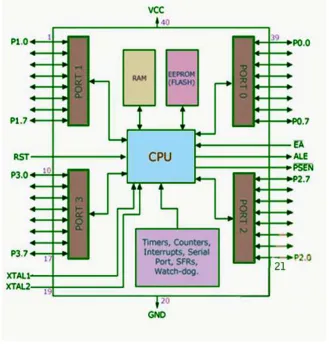
2. BLOCK LEVEL DESCRIPTION
2
Fig. 1: Block Diagram of 8051 Microcontroller [2]
Input:-GPS L1 Signal
Output:-Earth Centered, Earth Fixed Coordinates, Latitude Longitude, Altitude
3
amplifier and a band pass filter. An active antenna is required due to the low transmit power of GPS satellites and the degradation and attenuation of the signal as it goes through the atmosphere.
2.1.1 SE4110L
In this paper the SE4110L is a complicated chipset consisting of a several sub-stages. The subsystems are very similar to those of a super heterodyne receiver with the addition of a high-frequency A/D converter. The device outputs the magnitude and sign of the received signal at 4.092 MHz the SE4110L will provide the digitally sampled GPS L1 signal to the Microcontroller.
2.1.2 Microcontroller
A micro-controller can be compared to a small stand alone computer, it is a very powerful device, which is capable of executing a series of pre-programmed tasks and interacting with other hardware devices.
CPU RAM ROM
I/O Timer Serial COM Port
3. METHODOLOGY
3.1.Design and Implementation of GPS Receiver
GPS modem a device that in used to receive signals from satellite and which also provide Information about latitude, longitude, time, speed etc . The GPS navigator is more popular In mobiles for they help us to track the road maps. There is an antenna in a GPS modem which Receives the satellite signals and transfers them to the modem. Through modem data is converted Useful information and sends the output in serial RS232 logic level format. The information about Latitude, longitude etc is sent continuously and accompanied by an identifier string. This paper show interfacing between GPS modem and 8051 microcontroller and extract the Location (latitude, longitude, altitude, speed, time etc) from the $GPRMC string and display it on LCD.
3.2. Interfacing between 8051 and GPS
4
Fig. 3: Interfacing between 8051 Microcontroller and GPS Receiver
3.3.Flowchart for Identifying Sentence Identifier
5
Fig.5: Flowchart for receiving and extracting data
4. RESULT
4.1.NMEA Output Messages
The NMEA-0183 Output Messages are shown as below:
NMEA Record Descriptions GPGGA Global positioning system fixed data: time, position, fixed type. GPGLL Geographic position: latitude, longitude, UTC time of position fix and status. GPGSA GPS receiver operating mode, active satellites, and DOP values. GPGSV GNSS satellites in view: ID number, elevation, azimuth, and SNR values. GPRMC Recommended minimum specific GNSS data: time, date, position, course, speed. GPVTG Course over ground and ground speed. GPZDA PPS timing message (synchronized to PPS).
6
stop bit, and no parity. Other output sentences, baud rate, and related configurations could be requested based on MOQ.
Single message example
$GPGGA,101229.487,3723.2475,N,12158.3416,W,1,07,1.0,9.0,M, , , ,0000*3E $GPGLL,2446.8619,N,12100.2579,E,060725.000,A,A*7E
$GPGSA,A,3,05,02,26,27,09,04,15, , , , , ,1.8,1.0,1.5*11
$GPGSV,3,1,12,07,62,081,37,16,61,333,37,01,60,166,37,25,56,053,36*74 $GPGSV,3,2,12,03,43,123,33,23,32,316,34,14,17,152,30,20,16,263,33*78 $GPGSV,3,3,12,19,17,210,29,06,08,040,,15,06,117,27,21,05,092,27*7E
$GPRMC,151229.487,A,3723.2475,N,12148.3416,W,0.13,309.62,120598,,,A*5F $GPVTG,,T,,M,0.00,N,0.0,K,A*13
7
Fig.6: Using 8051Microcontroller Receive GPS Data
5. CONCLUSION
This work is used in Vehicle Tracking System, it is the technology used to determine the location of a vehicle using different methods like GPS and other radio navigation systems operating through satellites and ground based stations. Vehicle information like location details, speed, distance traveled etc. can be viewed on a digital mapping with the help of a software via Internet. Even data can be stored and downloaded to a computer from the GPS unit at a base station and that can later be used for analysis.
References
[1] ARINC, NAVSTAR GPS Space Segment/Navigation User Interfaces.
[2] Automatic GPS-Based Vehicle Tracking and Localization information System By Rosen Ivanovo, Ph.D., Dep. of Computer System
and Technologies Bulgaria(Research paper), E-mail ID- [email protected].
[3] Betz, J. Winter 2001-2002,”Binary Offset Carrier Modulations for Radio navigation,” NAVIGATION: Journal of The Institute of
Navigation, Vol. 48, No. 4,.
[4] GPS Manual Pro Gin SR-95 GPS Receiver. Taiwan Http:www.progin.com.tw, Sales contact: [email protected]
[5] Simon, M., et al. (1994), Spread Spectrum Communications Handbook, New York: McGraw-Hill.
[6] About vehicle Tracking Wikipedia http://www.google.com
[7] Muhammad Ali Mazidi,(2006) Janice Gillispie Mazidi ,Rolin D.Mckinlay ,for Interfacing Programming:-Second Edition, New