VISUAL LANGUAGE EDITORS BASED ON
LR PARSING TECHNIQUES
Gennaro Costagliola
and
Vincenzo Deufemia
Dipartimento di Matematica e Informatica
Universit´
a di Salerno
84081 Baronissi (SA), Italy
{
gcostagliola, deufemia
}
@unisa.it
Abstract
Visual language editors should provide a user-friendly environment where users are supported in an effective way in the construction of visual sentences. In this paper, we propose an approach for the construction of syntax-directed visual language editors by integrating incremental parsers into free-hand editors. The approach combines the LR-based techniques for parsing visual languages with the more general incremental Generalized LR parsing techniques developed for string languages.
1
Introduction
Visual languages are widely used in several application fields: teaching, development of GUIs, software development process (examples of modeling languages are UML, Petri Nets, automata, etc.). Such tasks require to be supported by a powerful visual environment within which the visual language is embedded and tightly integrated. To this aim, in recent years much effort has been devoted to the development of tools that assist the designer in the specification and implementation of visual environments [2, 4, 6, 8, 9]. Traditionally, such environments encompass a visual editor and a compiler for the specified language.
The two standard interaction models for diagramming software are free-order editing and syntax-directed model. In the free-order editing approach there is a clean separation of the concerns of the graphical editing and the interpretation of diagrams. The user draws the diagram in free order and then invokes the language analyzer to interpret the drawing. The analyzer informs the user about any errors it finds during parsing and semantic processing. This approach to visual language implementation makes it possible to combine the sketching and the checking of diagrams into an explorative style of constructing visual programs, and reduces the complexity of the implementation.
represented by the diagram. In a less restrictive approach the editor may report errors when they occur, but allowing continuation.
In this paper we propose an approach based on LR parsing for the construction of visual language editors that combines the positive aspects of both editing modes. In particular, such editors support the editing of visual sentences in free-order form. Moreover, the underlying parsers incrementally analyze the sentences, during their construction, providing an immediate feedback to the user.
The paper is organized as follows. Section 2 describes the main characteristics of the Extended Positional Grammars. Section 3 shows an incremental LR-based methodology for the parsing of visual languages modeled through XPGs. Section 4 illustrates how the parser can be integrated into a visual editor to support the user in the construction of visual sentences. Conclusions conclude the paper.
2
Extended Positional Grammars
In this section we illustrate the main characteristics of the eXtended Positional Grammars
(XPG, for short).
In order to represent visual sentences, the XPG formalism uses an attribute-based approach [7]. In this approach a sentence is conceived as a set of attributed symbols. The attributes of each symbol can be classified in physic, syntactic, and semantic attributes. The values of the syntactic attributes are determined by the relationships holding among the symbols. Thus, a sentence is specified by combining symbols with relations. As an example, a state transition diagram could be specified by providing the symbols representing nodes and edges, and the relations between them. In particular, the syntactic attribute to express the attachment relation between the borderline of a node and the end point of edges can be represented by an “attaching region” on that node.
More formally, an Extended Positional Grammar is the pair (G, PE), where PE is a positional evaluator, and G is a particular type of context-free string attributed grammar (N, T∪POS, S, P) where:
• N is a finite non-empty set ofnon-terminal symbols;
• T is a finite non-empty set ofterminal symbols, with N∩T=∅;
• POS is a finite set ofbinary relation identifiers, with POS∩N=∅ and POS∩T=∅;
• S∈N denotes thestarting symbol;
• Pis a finite non-empty set ofproductions of the following format:
A→x1R1x2R2. . . xm−1Rm−1xm,∆,Γ
where A is a non-terminal symbol, x1R1x2R2. . . xm−1Rm−1xm is a linear representation with respect to POS where eachxi is a symbol in N∪T and each Rj is partitioned in two sub-sequences
( RELh1
j1, . . . , REL hk
jk, REL hk+1
jk+1, . . . , REL hn
Each RELhi
ji relates syntactic attributes of xj+1 with syntactic attributes of xj−hi, with 0≤hi<j. In the rest of the paper, we will denote REL01 simply as REL1. The relation identifiers in the first sub-sequence of anRj are calleddriver relations, whereas the ones in the second sub-sequence are calledtester relations. Driver relations are used during syntax analysis to determine the next symbol to be scanned, whereas tester relations are used to check whether the last scanned symbol (terminal or non-terminal) is properly related to previously scanned symbols. We refer to the driver (tester, resp.) relations of Rj with driver(Rj) (tester(Rj), resp.). Without loss of generality we assume that there are no useless symbols, and no unit and empty productions [1].
∆ is a set of rules used to synthesize the values of the syntactic attributes of A from those of x1, x2,. . .,xm.
Γ is a set of triples (Nj,Condj, ∆j)j=1,..,t, t≥0, used to dynamically insert new symbols in the input visual sentence during the parsing process. In particular,
– Njis a terminal symbol to be inserted in the input visual sentence;
– Condj is a pre-condition to be verified in order to insertNj;
– ∆j is the rule used to compute the values of the syntactic attributes ofNj from those of x1,. . ., xm.
Informally, a Positional Evaluator PE is a materialization function that transforms a lin-ear representation into the corresponding visual sentence in the attribute-based representation and/or graphical representation. The attribute-based representation of a visual sentence is a list of all the objects forming the sentence together with the values of their syntactic attributes. In the following we characterize the languages described by an extended positional grammar XPG = ((N, T∪POS, S, P), PE). We write α ⇐β and say that β reduces to αin one step, if there existδ, γ, A, η such that A→ η, ∆, Γ is a production in P, β = δηγ, α = δAπγ, where A is a symbol whose attributes are set according to the rule ∆ andπ results from the application of the rule Γ.
We also writeα⇐i β to indicate that the reduction has been achieved by applying production i. Moreover, we writeα⇐∗ β and say thatβ reduces toα, if there existα0,α1,. . .,αm(m≥0) such thatα=α0⇐α1⇐. . .⇐αm=β. The sequenceαm,αm−1,. . .,α0is called aderivation ofαfrom β.
• apositional sentential form from S is a stringβ such that S ⇐∗ β;
• apositional sentence from S is a stringβ containing no non-terminals and such that S⇐∗ β;
• avisual sentential form (visual sentence, resp.) from S is the result of evaluating a positional sentential form (positional sentence, resp.) from S through PE.
The language described by an XPG, L(XPG), is the set of the visual sentences from the starting vsymbol S of XPG.
For some relations it is possible to specify semantically opposed relation. In particular,
let REL1 and REL2 be two relation identifiers, if x REL1 y and y REL2 x hold for any
pair of symbols x and y then REL2 is the opposed relation of REL1 and vice versa. In
exists inv(R) for each R in POS then XPG is named reversible. It is worth noting that for some relations it may happen that inv(R)=R. Now, we are ready to introduce the con-cept of reverse grammar for XPGs that will be useful for the final incremental parsing algorithm.
Definition 2.1. Let G=((N, T∪POS, S, P), PE) be a reversible XPG. A reverse grammar with respect to G, denoted with rev(G), is an XPG G=((N, T∪POS,
Note that L(G) is equivalent to L(rev(G)) for each reversible XPG grammar G.
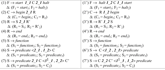
In the following we show two examples of XPG grammars, the first describing a Flow-Chart language, and the second modeling a State Transition Diagram language.
Example 2.1. The following extended positional grammar FlowCharts generates struc-tured flow-charts with loops. The set of non-terminals is given by N ={F, C, S, R} and F is the starting symbol. The terminal symbols of the grammar are graphically depicted in figure 1. Here, each attaching point is represented by a circle and is identified by a number. In the
start halt function
Figure 1: The terminals for the grammar FlowCharts.
following, the notationV symi denotes the attaching point i of the symbolV sym. The set of relations is given by POS ={LINKh,k}, where the relation identifier LINKi,j is defined as: “a symbolxis in relation with a symboly iff attaching pointi ofxis connected to attaching point j of y”, and will be denoted as i j to simplify the notation. Moreover inv(h k)=k h. The set of productions forFlowChartsandrev(FlowCharts) follow.
(1) F → start 1_1 C 2_1halt
The production 1) defines a flow-chart F as a compound statement C delimited by thestart
and halt terminal symbols. In production 2) a compound statement C is defined as a begin
sequence of statements S ending with theend symbol. Productions 5), 6) and 7) describe a statement S as a simplefunction, a WHILE loop construct, and an IF THEN ELSE construct, respectively. Note that the starting non-terminal F has no attaching points, while all the other non-terminals have two attaching points. Figure 2 shows a flow-chart described by the previous grammars.
start
predicate
function
halt end
end begin
begin
Figure 2: A flow-chart.
Example 2.2. Let STD= ((N, T∪POS, S, P), PE) be the XPG for State Transition Dia-grams, characterized as follows.
The set of non-terminals is given by N ={StateTD, Graph, Node} where each symbol has one attaching region as syntactic attribute, and StateTD is the starting symbol, i.e. S =
StateTD. The set of terminals is given by T ={NODEI, NODEIF, NODEF, NODEG, EDGE,
PLACEHOLD} (see figure 3). The terminal symbols NODEI, NODEIF, NODEF, NODEG
have one attaching region as syntactic attribute. They represent, the initial, the initial and
final, thefinal, and thegeneric node, respectively, of a state transition diagram. The terminal symbol EDGE has two attaching points as syntactic attributes corresponding to the start and end points of the edge. Finally, PLACEHOLD is a fictitious terminal symbol to be dynamically inserted in the input sentence during the parsing process. It has one attaching region as syntactic attribute. In figure 3, each attaching region is represented by a bold line and is identified by
1 1
NODEI NODEIF NODEF NODEG EDGE PLACEHOLD 1 1
1 2
1
Figure 3: The terminals for the grammar STD.
the number 1, whereas the two attaching points of EDGE are represented by bullets and are identified each by a number. The set of relations is given by POS ={LINKh,k,any}where the relation identifierany denotes a relation that is always satisfied between any pair of symbols, whereasLINKh,k is defined as in the previous example. Moreover, we use the notation h k when describing the absence of a connection between two attaching areash andk.
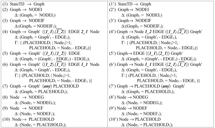
Next, we provide the set of productions for describing State Transition Diagrams. In
particular, we present the productions of STD and rev(STD). Notice that Graph1 =
Graph1 - EDGE1 indicates set difference and is to be interpreted as follows: “the at-taching area 1 of Graph has to be connected to whatever is attached to the
attach-ing area 1 of Graph except for the attaching point 1 of EDGE”. Moreover the
(1) StateTD → Graph
According to these rules, a State Transition Diagram is described by a graph (production 1) defined as an initial node (production 2) or as an initial-final node (production 3) or, recursively, as a graph connected to a node through an outgoing (production 4) or incoming (production 6) edge, or as a graph with a loop edge (production 5). A node can be either a generic node (production 8) or a final node (production 9).
Figure 4 shows a sentence described by both grammars above.
1
3 2
Figure 4: A state transition diagram.
3
Incremental Generalized XpLR Parsing
The idea behind the definition of the XPG formalism is to overcome the inefficiency of the visual languages syntactic analysis by researching efficient parsing algorithms based on suitable extensions of the well-known LR technique. As a result, some versions of the formalism have been defined and new more powerful parsing algorithms have been devised, thus allowing the specification and the analysis of more complex classes of visual languages. In particular, parsers based on XPG are based on an extension of LR parsing, namedXpLR parsing [7].
A peculiarity of XpLR parsers is its scanning of the input in a non-sequential way (driven by the relations used in the grammar). However, this increases the occurrence of parsing conflicts. Indeed, an XpLR parser suffers from the same drawbacks as any other deterministic table-driven parser: the language grammar must be unambiguous and conform to the limitations of the particular table-generation algorithm, which, in many cases, is quite restrictive and requires significant “grammar-hacking”.
corresponds to abstract syntax. GLR parsing handles conflicts successfully by using a graph-structured stackand by representing the possible parse tree in a compact way (thepacked shared parse forest). Additionally, GLR permits a syntactically ambiguous grammar specification, which is necessary because the syntax of many languages, included the visual ones, falls outside the LR(k) class of languages. Moreover, an XpLR parser as defined in [7] does not provide any feedback while the user composes a sentence. In the case of visual languages this is not desirable since a visual environment needs to be interactive in order to make the user comfortable with its use. In order to give immediate feedback to the user, a visual interactive environment requires then the use of incremental parsing methods. To this aim, the XpLR parser has been made generalized and incremental.
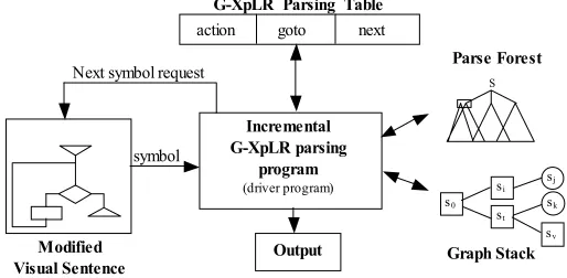
The Incremental Generalized XpLR parser (IG-XpLR parser, for short) is based on ideas first introduced in [3]. The components of an IG-XpLR parser are shown in figure 3.1 and are detailed in the following.
action goto next
G-XpLR Parsing Table
Incremental G-XpLR parsing
program
(driver program)
Modified
Visual Sentence Graph Stack
symbol Next symbol request
Output
s0
st
sj
sk
si
sv
Parse Forest
S
Figure 5: The architecture of an Incremental Generalized XpLR parser.
The input to the incremental parser is a dictionary storing the attribute-based representation of the modified visual sentence as produced by the visual editor, a parse forest and a graph stack built on the original visual sentence. The parser matches the modified visual sentence with the yield of the parse forest, restructures the parse forest on the base of the modifications, and updates the graph stack. The match is accomplished by retrieving the objects in the dictionary through theFetch Symbol function driven by the relations in the grammar.
been parsed, respectively. The action and goto entries are namedconditioned actions and have the format “Rtester: state” and “Rtester: shift state”, respectively, whereRtester is a possibly empty sequence of tester relations. A shift or goto action is executed only if all the relations in
Rtester are true, or if Rtester is empty.
Other than the traditional shift-reduce and reduce-reduce conflicts, a G-XpLR parsing table presents apositional conflict if there exists an entry of the next section containing more than one element, and a shift-shift conflict (goto-goto conflict, resp.) if the action section (goto section, resp.) presents an entry with more than one conditioned action with conditions that are not mutually exclusive [7]. The IG-XpLR permits these tables to contain conflicts: when a state transition is multiply defined, the IG-XpLR parser simply forks multiple parsers to follow each possibility.
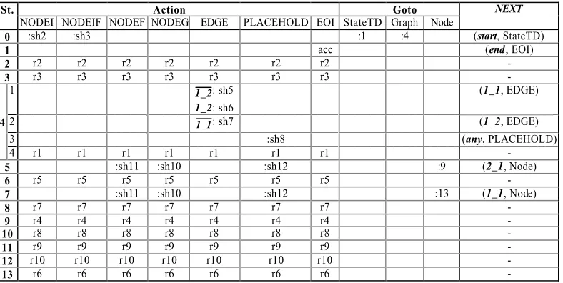
As an example, figure 6 shows the G-XpLR(0) parsing table for the grammar of state tran-sition diagrams given in example 2.2. State 4 presents four possible actions:
(i) sh5 (sh6, resp.) on seeing an outgoing edge (a self-edge, resp.) (corresponding to substate 4.1),
(ii) sh7 on seeing an incoming edge (substate 4.2),
(iii) sh8 on seeing an reintroduced symbol PLACEHOLD (state 4.3),
(iv) r1: reduce by rule (1) “StateTD→Graph”.
Thus, when a state has more than one substate the parser non-deterministically invokes a functionFetch Symbol on each pair (R, x) of thenext section.
St. Action Goto NEXT
NODEI NODEIF NODEF NODEG EDGE PLACEHOLD EOI StateTD Graph Node
0 :sh2 :sh3 :1 :4 (start, StateTD)
1 acc (end, EOI)
2 r2 r2 r2 r2 r2 r2 r2 -
3 r3 r3 r3 r3 r3 r3 r3 -
1 1 2_ : sh5
1_2: sh6
(1_1, EDGE)
4 2 1 1_ : sh7 (1_2, EDGE)
3 :sh8 (any, PLACEHOLD)
4 r1 r1 r1 r1 r1 r1 r1 -
5 :sh11 :sh10 :sh12 :9 (2_1, Node)
6 r5 r5 r5 r5 r5 r5 r5 -
7 :sh11 :sh10 :sh12 :13 (1_1, Node)
8 r7 r7 r7 r7 r7 r7 r7 -
9 r4 r4 r4 r4 r4 r4 r4 -
10 r8 r8 r8 r8 r8 r8 r8 -
11 r9 r9 r9 r9 r9 r9 r9 -
12 r10 r10 r10 r10 r10 r10 r10 -
13 r6 r6 r6 r6 r6 r6 r6 -
Figure 6: The G-XpLR(0) parsing table for example 2.2.
The techniques used to support the incrementality derive from the Incremental GLR (IGLR) parser presented in [13]. As the authors state: “It combines subtree reuse in deterministic regions with GLR methods in areas requiring non-deterministic parsing”. Since the XpLR parser does not make use of lookaheads our algorithm does not need to track lookhead infor-mation. Moreover, as another difference, the symbols of the sentence are scanned through the
Fetch Symbol function in order to identify the modifications.
4
A Syntax-directed Editor based on IG-XpLR Parsing
In this section, we illustrate how the parser described in the previous section can be effectively integrated into a graphical editor to support the syntax-directed editing of visual sentences.
In our approach the parsing algorithm is invoked by the editor as the visual sentence is modified, and it is immediately possible to tell whether the sentence edited so far is accepted or not, just by looking at the parser state.
It is worth noting that in the LR parsing of visual languages it is difficult to establish from which symbol of a sentence the parsing process has to start. In [5] an algorithm has been presented that makes use of two pGLR parsing tables and can be easily extended to the in-cremental IG-XpLR parser. The idea is to use two parsers that proceed in parallel, scanning the input sentence in opposite directions from an arbitrary starting symbol. The algorithm is based on the concepts of substring parsing as presented in [10]. In particular, the algorithm creates the G-XpLR parsing tables for the original XPG grammar G and for its reverse version
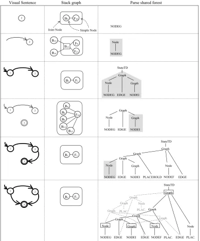
rev(G). Obviously, this restricts the applicability of the algorithm to reversible XPGs. Figure 7 shows the G-XpLR(0) parsing table forrev(STD), the reverse grammar given in example 2.2. For each state in G (rev(G), resp.) reachable after the occurrence of the starting symbol the algorithm starts an incremental IG-XpLR parser, namedforward(backward, resp.). The forward parsers interact with the backward parsers only when a parser tries to reduce a production. In this case, that parser waits for a rendezvous, i.e., an opposite parser attempting to apply the reverse version of the same reduction. The forward and backward parser stacks can be considered as only one graph stack expanding to the right and to the left, and with two types of nodes: simple stacknode and joint stacknode. The latter encloses a bipartite graph whose elements are simple stack nodes from forward and backward parsers. The incremental parser must control that the rendezvous operation can be applied before reusing a subtree. Moreover, the reintroduction of the terminals is local to the couple of forward and backward parsers that execute the rendezvous. Figure 8 shows an example of application of such algorithm to the state transition diagram described in figure 4. The first column visualizes the different sentences edited during the composition. The editor uses three colors to support the user in the composition of the visual sentences. In particular, if the sentence is correct then it is visualized green, otherwise the symbols recognized by the parser are visualized blue, while the unparsed symbols are black. In figure 8 such colors correspond to bold, black and gray, respectively.
St. Action Goto NEXT
NODEI NODEIF NODEF NODEG EDGE PLACEHOLD EOI StateTD Graph Node
0 :sh2 :sh3 :sh10 :sh9 :sh5 :sh7 :1 :4 :11 (start, StateTD)
1 acc (end, EOI)
2 r2 r2 r2 r2 r2 r2 r2 -
3 r3 r3 r3 r3 r3 r3 r3 -
4 r1 r1 r1 r1 r1 r1 r1 -
5 2_1: sh2 2_1:sh3 2_1:sh10 2_1:sh9 2_1:sh5 2_1:sh7 2_1:6 2_1:11 (1_1, Graph)
6 r5 r5 r5 r5 r5 r5 r5 -
1 :sh2 :sh3 :sh10 :sh9 :sh5 :sh7 :8 :11 (any, Graph)
7 2 r10 r10 r10 r10 r10 r10 r10 -
8 r7 r7 r7 r7 r7 r7 r7 -
9 r8 r8 r8 r8 r8 r8 r8 -
10 r9 r9 r9 r9 r9 r9 r9 -
1 :sh12 (1_2, EDGE)
11 2 :sh14 (1_1, EDGE) 12 2_1:sh2 2_1:sh3 2_1:sh10 2_1:sh9 2_1:sh5 2_1:sh7 2_1:13 2_1:11 (1_1, Graph)
13 r4 r4 r4 r4 r4 r4 r4 -
14 1 1_ :sh2 1 1_ :sh3 1 1_ :sh10 1 1_ :sh9 1 1_ :sh5 1 1_ :sh7 1 1_ :15 1 1_ :11 (2_1, Graph)
15 r6 r6 r6 r6 r6 r6 r6 -
Figure 7: The G-XpLR(0) parsing table for the reverse grammar of example 2.2.
up, and the backward one enters in a wait state, trying to reduce with production (1’), until the forward parser completes the recognition of the sentence and tries to reduce with production (1). However, each tree in a parse forest represents an interpretation of the sentence. By default the editor visualizes in blue the symbols of the parse tree with more leaves, but the user can require to visualize another one. In the same way, the user can change the starting symbol.
This approach is being integrated into the Visual Language Compiler-Compiler (VLCC) system [6], a visual environment generation system based on the XPG model that inherits, and extends to the visual field, concepts and techniques of compiler generation tools like YACC. Such tool assists the visual language designer in the specification of the grammar and of the graphical symbols, and automatically generates a visual environment (see figure 9). The visual editor and the parser interact through a Control Module that invokes the incremental parser when the sentence is modified, and analyzes the parse forest constructed by the parser in order to create the new layout of the sentence.
5
Conclusions
We have presented an LR-based approach for the construction of visual language editors that combines the positive aspects of free-hand editing and syntax-directed editing. During the construction of a sentence the editor, which is tailored to a specific visual language, interacts with the incremental LR-based parser that provides an immediate feedback to the user. This approach is being integrated into the VLCC [6], a system for the automatic generation of visual programming environments.
In the future we will investigate how to extend the functionality of the editor by offering additional support to the user in the construction of the sentences. In particular, the editor can exploit the information in the parsing table to suggest the user how to construct the visual sentence in an easier and more effective way.
References
[1] A.V. Aho, R. Sethi, and J.D. Ullman.Compilers, principles, techniques and tools. Addison-Wesley, 1985.
[2] R. Bardhol. GenGEd - A Generic Graphical Editor for Visual Languages Based on
Al-gebraic Graph Grammars. In Procs. 1998 IEEE Symposium on Visual Languages, pages
48–55, Halifax, Nova Scotia, September 1998.
[3] S.K. Chang, G. Costagliola, and M. Tomita. Parsing 2D Languages by a Pictorial GLR Parser. In S. Levialdi T. Catarci, M.F. Costabile, editor, Advanced Visual Interfaces, volume 36 of World Scientific Series in Computer Science, pages 319–333, May 1992.
[4] S.S. Chok and K. Marriott. Automatic Construction of Intelligent Diagram Editors. In
Proceedings of the ACM Symposium on User Interface Software and Technology UIST98, pages 185–194, San Francisco, California, 1998.
[5] G. Costagliola. (Pictorial) LR Parsing from an Arbitrary Starting Point. In Procs. of SIGPARSE/ACL Third International Workshop on Parsing Technologies, pages 49–58, August 1993.
[6] G. Costagliola, A. De Lucia, S. Orefice, and G. Tortora. A Parsing Methodology for the Im-plementation of Visual Systems. IEEE Transactions on Software Engineering, 23(12):777– 799, 1997.
[7] G. Costagliola and G. Polese. Extended Positional Grammars. InProceedings of 16th IEEE Symposium on Visual Languages, pages 103–110, Seattle, WA, USA, September 2000.
[8] O. K¨oth and M. Minas. Generating Diagram Editors Providing Free-Hand Editing as
well as Syntax-Directed Editing. In Procs. GRATRA’2000 - Joint APPLIGRAPH and
GETGRATS Workshop on Graph Transformation Systems, pages 32–39, March 2000.
[9] K. Marriott and B. Meyer, editors. Visual Language Theory. Springer-Verlag, 1998.
[10] J. Rekers and W. Koorn. Substring Parsing for Arbitrary Context-Free Grammars. In
Procs. of Second International Workshop on Parsing Technologies, pages 218–224, Febru-ary 1991.
[11] M. Tomita, editor. Efficient Parsing for Natural Languages. Kluwer, Boston, 1985.
[12] M. Tomita, editor. Generalized LR Parsing. Kluwer, Boston, 1991.
1
Figure 8: Syntax-directed editing of the state transition diagram in figure 4.
Visual