Design and Implementation of MPC-SVM
Method for Vienna Rectifier with PMSG
R.Srikanth
M.E.(Bio Medical Engineering), UCEOU
Vuppari Prabhakar
M.Tech(Energy Systems), JNTUCEA
S.Vijay Kumar
M.Tech(Digital Systems And Computer Electronics), JNTUH
ABSTRACT:In this paper to design and implement
thepermanent magnet synchronous generator
(PMSG) basedwind energy conversion system (WECS) using with an Vienna rectifier. To combined with grid with two back to backconnected converters with a common DC link. The permanentmagnetic
synchronous generator (PMSG) which
feedsalternating current (AC) power to the utility grid connection .In this paper a learning of WECS is done by using a constantspeed direct using MATLAB software. Even that dc link voltageat its reference value, the output ac voltage of the inverter canbe kept constant. An effective control techniques to extractgrid side controller also called voltage and current controller,three phase transformer.
KEYWORDS-Permanent magnet synchronous generator (PMSG), wind energy conversion system(WECS), converter using MOSETs based
I. INTRODUCTION
The world consumption of energy has knownenormous increase these last years, because of themassive industrialization that has tendency to intensifyrapidly in some geographical areas in the world, notablyin countries of Asia. The risks of shortage of fossilmatters and their effects on the climatic change indicateonce more the importance of renewable energies. Severalsources of renewable energies are under exploitation andsearch, in order to develop power extraction techniquesaiming to improve the reliability, lower the costs (ofmanufacture,
Many control methods for the Vienna rectifier have beenproposed. In the Vienna rectifier, one of the main control aims is tomake the input currents to have sinusoidal waveforms. The hysteresiscurrent control method is used and it is a classic control method. Theswitching set is determined by the rule defined from the hysteresiscurrent control.
Fig.1. Typical configuration of PMSG based variable speed windenergy conversion system
The classic linear controllers such as the
proportionalintegral controller are used and the switching set is generated bycomparing the reference voltages with the carrier voltages or by thespace vector modulation method. The aforementioned controlmethods have been widely used in other topologies such as two-levelconverter and three-level converter. The Direct Torque Control (DTC)method and the Model Predictive Control (MPC) method with costultfunction have been proposed for the applications using a motor orgenerator. Research on the DTC and MPC methods at two-levelconverter, three-level converter, and matrix converter are beingcarried out consistently. Recently, DTC method for the Viennarectifier was proposed.
Disadvantages:
Neutral-point voltage unbalancing problem Variation of the power factor
1) Continuous- and discrete-time modeling of power converters and WECS
The optimal control actions of the predictive control strategy are mainly based on themodel of the system. A poor modeling of the system will lead to an inferior controlperformance. The continuous-time models should
be converted to discrete-time witha suitable method such that control delay and prediction horizon can be incorporated.In this work, the third objective is set to accurately model different control variablesin terms of converter switching states.
2) Performance improvement of predictive control strategy
Despite many best features of FCS-MPC strategy, several challenges are reported inthe state-of-the-art literature. A few examples include: weighting factors selection,control delay compensation, accurate extrapolation of reference control variables, variable switching frequency nature, prediction of variables over two or more samples withreduced computational burden, and enhancement of robustness against perturbationsin the system model.In this paper, the next objective is defined to address the above challenges, andto promote the FCS-MPC strategy as the one of the next generation control tools.
3) Development of generalized control strategy for multilevel diode-clamped converters (MLDCCs)
In this work, 3L and 4L converters are proposed for the MW-WECS, and thus thecontrol scheme developed for one converter should work for the other, too. In classical control (which is a mature subject matter), many works have been presented to
generalize the control of load current, dc-link capacitor voltages and common-modevoltage in MLDCCs. But in the current predictive control research area, this issue isnot addressed yet.
4) Development of efficient controllers for the grid-tied MLDCCs
The grid-tied MLDCCs play a crucial role in dispatching wind power and also to meetgrid codes. The control techniques for the grid-side converter should perform multipletasks to ensure proper and reliable operation of WECS.The next objective is specified to design efficient
controllers such that grid-tied MLDCCcontrol
switching frequency operation can be fulfilled simultaneously.
5) Design of decoupled control system for the PMSG-WECS
In order to achieve decoupled operation for the generator- and grid-side converters, thecontrol systems should be properly designed. In addition to the aforementioned gridside control requirements, the MPPT operation should be performed by the generatorside converter. The control systems should generate reference control variables in orderfor the WECS to operate at higher efficiency.The next objective of this work is the design and implementation of sophisticated control systems for efficient operation of three-level and four-level converter-based WECS.
6) LVRT enhancement for the proposed WECS using FCS-MPC strategy
The state-of-the-art LVRT solutions for PMSG-WECS include pitch control system,over sizing of dc-link capacitors, dissipation of surplus energy in dc-link crowbar (resistor), storage of surplus energy in the battery banks and fly-wheel systems, use ofpower quality conditioning devices. The surplus energy can be stored in the mechanicalsystem inertia during the grid voltage dips, and this issue is previously analyzed withCSC and NPC converters, and with classical control techniques. The complete WECSresponse with passive generator-side converters has not been explored yet.The last objective is defined to develop a FCS-MPC control system such that thepower converters operate in a safe mode (by maintaining constant dc-bus voltage),while meeting the grid code requirements.
II. PROPOSED STRATEGY
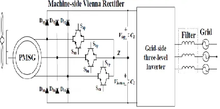
This project proposes the MPC method for the Vienna rectifierused in WTS with a Permanent Magnet Synchronous Generator(PMSG). The proposed MPC method considers the feasible eightvoltage vectors of the Vienna rectifier; moreover, the additionalvoltage vectors, which are the center voltage vectors of two
feasibleadjacent voltage vectors, are taken into
consideration to improve theperformance of the MPC method. In the proposed MPC method, theerrors in
d/q-axis current are predicted based on model of the PMSG,and then, the optimized voltage vector is selected by cost function forthe current ripple minimization. Additionally, from the optimizedvoltage vector, N-type and P-type voltage vectors, which give thedifferent effect on the neutral-point voltage, are considered inselecting the final switching set to solve the neutral-point voltageunbalancing problem. The final switching set is generated by theSpace Vector Modulation (SVM) method.
Fig. 2 : Proposed system of Vienna rectifier
Advantages:
Ripple minimization of PMSG currents No neutral-point voltage unbalancing problem
Applications:
Telecommunication systems Wind turbine systems (WTS)
Simulation parameters are as listed are:
The parameters are designed to get the output of desirelevels. Simulation time is 5μS and switching frequency orfrequency of repetitive sequence is 50 KHz for various inputvoltages the output is the valve for wind power generationand we get varying the input voltage.
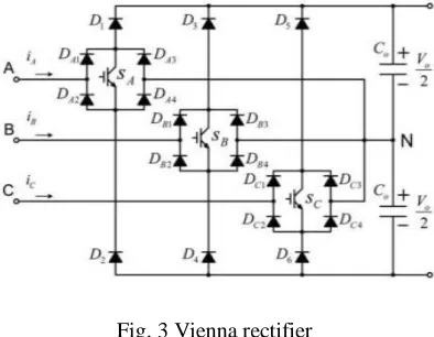
phase andthree levels VIENNA rectifier in the interfaces. The Vienna rectifier consists of three switches MOSETs; Itconverts the AC voltage into control output voltage. It canalso provide sinusoidal input currents and control outputvoltage. The AC voltage from the three phase generator isgiven to the Vienna rectifier. The current flows through thethree MOSETs and the capacitors in the fully charged it.The phase current rises, through a MOSFETs, during thatpulse period, charge the capacitor. When the MOSFETs isturned off, current through the diode upper or lowerdepending on direction of the current flow. By adjust thewidth of the pulse that turns ON the MOSFETs,corresponding line current is forced to be sinusoidal and inphase with the Voltage. When the MOSFETs is turned ONthe corresponding phase is connected the line inductor, tothe center point between the two output capacitors.
Fig. 3 Vienna rectifier
Table 1: List Of Simulation Parameters And Its Values
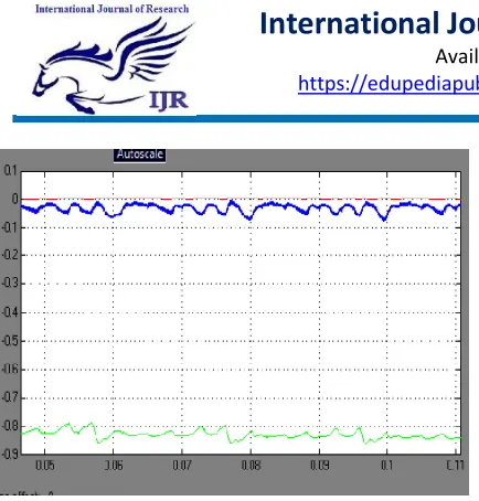
III. SIMULATION RESULTS
The given simulation Output result gives us power factorinput voltage and current across the capacitor, finally output.
Fig. 4 : Three Phase Switching Waveform
Fig. 5 : Phase A Input Voltage And Current Waveform
Fig. 7 : Reference Current Waveform
Fig. 8 : Reference Voltage And Current Generation
IV. CONCLUSION
To study the control strategies and designs the simulationof system PMSG in AC power to the utility grid in Matlab. Thesimulation results display that the AC to connected the DCcapacitor link output. DC-link voltage is kept at stable levelfor control of active and reactive power. Henceforth, the outputwill get the power supply for the systems.
REFERENCES
[1] Jay Verma,Yogesh , Tiwari, Anup Mishra, Nirbhaya Singh,‖Performance, Analysis and Simulation of Wind EnergyConversion System Connected with grid‖. IJRTE, ISSN: 2277-3878 Volume-2, Issue-6, January2014.
[2]D Mary,ShinoshMathew,SreejithK,,‖Modeling
andSimulation of Grid Connected Wind
EnergySystem.‖,IJSCE,ISSN: 2231-2307,
Volume-3,Issue-1, andMarch 2013.
[3] A.Bharathisankar, Dr.R.Seyezhai,‖MATLAB
Simulation ofPower Electronic Converter for PMSG
Based Wind EnergyConversion
System‖,IJIREEICE,Vol.1,Isuue.8,November 2013
[4] Gaurav Singh
Bhandari,Dr.M.Kowaslya,‖PowerElectronics Converter
for Grid IntregratedVriable
SpeedWindTurbine‖,IJDR,Vol.4,Issue.3,March 2014
[5] RajveerMittal,K.S.Sandhu,D K. Jain,‖Grid Voltage
Controlof Inverter Interfaced Wind Energy
ConversionSystem‖,IJESD,Vol.2,Issue.5,October 2011.
[6] J. Chen, H. B. Wu, M. Sun, W. N. Jiang, L. Cai, and C. Y. Guo,―Modeling and simulation of directly driven wind turbinewith permanent magnet synchronous generator,‖ inProceedings of the 2012 IEEE Innovative Smart GridTechnologies, Asia (ISGT '12), pp. 1–5, May 2012.
[6] B. Robyns, M. Esselin, ―Power control of an
invertertransformer association in a wind
generator‖,Electromotion, vol 6, n°1-2, 1999, pp3-7.
[7] M. Chinchilla, S. Arnaltes, J. Carlos Burgos, "Control
ofPermanent-Magnet Generators Applied to
VariableSpeed Wind-Energy Systems Connected to the Grid ",IEEE Transaction on energy conversion vol 21, n°, 1,Mars 2006.
[8] B. Robyns, M. Esselin, ―Power control of an
invertertransformer association in a wind
generator‖,Electromotion, vol 6, n°1-2, 1999, pp3-7.
[9] R. Pena, J. C. Clare, and G. M. Asher, ―Doubly
fedinduction generator using back-to-back PWM
convertersand its application to variable-speed wind-energygeneration‖, Proc. Inst. Elect. Eng.—Elect. Power Appl.,vol. 143, no. 3, pp. 231–241, May 1996.
STATCOM versus SVC. IEEE Trans. Power Electron. 2008, 23, 1104–1117.
[11]. Nguyen, T.H.; Lee, D.C.; Song, S.H.; Kim, E.H. Improvement of Power Quality for PMSG WindTurbine Systems. In Proceedings of the Energy Conversion Congress and Exposition (ECCE2010), Atlanta, GA, USA, 12–16 September 2010.
[12]. Li, J.; Li, D.; Hong, L.; Xie, C.; Chen, G. A Novel Power-Flow Balance LVRT Control Strategyfor Low-Speed Direct-Drive PMSG Wind Generation System. In Proceedings of the IECON2010–36th Annual Conference on IEEE Industrial Electronics, Glendale, AZ, USA, 7– 10November 2010.
[13]. Singh, M.; Khadkikar, V.; Chandra, A. Grid
synchronisation with harmonics and reactive
powercompensation capability of a permanent magnet synchronous generator-based variable speed windenergy conversion system. IET Power Electron. 2011, 4, 122– 130.
[14]. Kim, K.; Jeung, Y.; Lee, D.; Kim, H. LVRT scheme of PMSG wind power systems based onfeedback linearization. IEEE Trans. Power Electron. 2012, 27, 2376–2383.
[15]. Geng, H.; Yang, G.; Xu, D.; Wu, B. Unified power control for PMSG-based WECS operatingunder different grid conditions. IEEE Trans. Energy Convers. 2011, 26, 822–830.
Authors Details:
R.Srikanth completed M.E.(Bio Medical Engineering) from UCEOU.
Vuppari Prabhakar Completed M.Tech(Energy Systems) from JNTUCEA.