Copyright to IJAREEIE DOI: 10.15662/ijareeie.2015.0407126 6729
Cascaded Multilevel Inverters for Photovoltaic
Power System Applications
Lalit Dutta1,Raj Kiran B2,V Siva Brahmaiah Rama3
PG Scholar [Power System], Dept. of EE, Mewar University, Chittorgarh, Rajasthan, India1
Assistant professor, Dept. of EE, Mewar University, Chittorgarh, Rajasthan, India2
Assistant professor, Dept. of EE, Mewar University, Chittorgarh, Rajasthan, India3
ABSTRACT: There is much significant recent advancement in the area of power electronics applications to the photovoltaic power system. Photovoltaic systems are becoming more widespread with the increase in the energy demand and it also reduces the environmental pollution around the world. Out of different structures of multi-level inverters, Cascaded H Bridge (CHB) inverter is more suitable converter for PV applications since each PV panel can act as a separate DC source for each cascade H bridge module. A mathematical model for the photovoltaic panel is developed and implemented with the multilevel inverter. There are many limitations in extracting power from renewable energy resources. To minimize the power demand and scarcity we have to improve the power extracting methods. Multilevel inverter can be used to extract power from solar cells. It synthesizes the desired ac output waveform from several dc sources. The main objective of this paper is to study the5-level and 7-level Cascaded Multilevel Inverter. In this paper the different parameters (like voltage, current, THD) in 5-level and 7-level Cascaded Multilevel Inverter are observed. By these observations it can be seen that the total harmonic distortion is reduced with the increase in the levels of Cascaded Multilevel Inverter and also as the levels increases the output approaches to the sine wave. Simulation works are done in MATLAB/Simulink.
KEYWORDS: Photovoltaic System, Inverters, Multilevel Inverters, Cascaded H-Bridge Multilevel Inverters, PWM Technique.
I.INTRODUCTION
Photovoltaic (PV) technology converts one form of energy (sunlight) into another form of energy (electricity) using no moving parts, consuming no conventional fossil fuels, creating no pollution, and lasting for decades with very little maintenance[1][2]. The use of a widely available and reasonably reliable fuel source, the sun with no associated storage or transportation difficulties and no emissions makes this technology eminently practicable for powering remote scientific research platforms. Indeed, numerous examples of successfully deployed systems are already available. The completely scaleable nature of the technology also lends itself well to varying power requirements–from the smallest autonomous research platforms to infrastructure-based systems. This technology can be limited, however, by annual fluctuations in solar insolation, especially at extreme latitudes.
Copyright to IJAREEIE DOI: 10.15662/ijareeie.2015.0407126 6730 The main objective of this paper is to study the 5-level and 7-level Cascaded Multilevel Inverter. In this paper the different parameters (like voltage, current, THD) 5-level and 7-level Cascaded Multilevel Inverter are observed. By these observations it can be seen that the total harmonic distortion is reduced with the increase in the levels of Cascaded Multilevel Inverter and also as the levels increases the output approaches to the sine wave.
II. PHOTOVOLTAIC SYSTEM
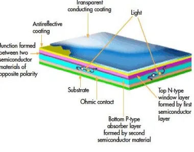
A solar cell, or photovoltaic cell, is an electrical device that converts the energy of light directly into electricity by the photovoltaic effect, which is a physical and chemical phenomenon[9]. It is a form of photoelectric cell, defined as a device whose electrical characteristics, such as current, voltage, or resistance, vary when exposed to light. Solar cells are the building blocks of photovoltaic modules, otherwise known as solar panels.
Figure 1: Solar cell
Photons of light with energy higher than the band-gap energy of PV material can make electrons in the material break free from atoms that hold them and create electron and hole pairs[12]. These electrons however, will soon fall back into holes causing charge carriers to disappear. If a nearby electric field is provided, those in the conduction band can be continuously swept away from holes toward a metallic contact where they will emerge as an electric current. The electric field with in the semiconductor itself at the junction between two regions of crystals of different type, called a p-n junction. The PV cell has electrical contacts on its top and bottom to capture the electrons. When the PV cell delivers power to the load, the electrons flow out of the n-side into the connecting wire, through the load, and back to the p-side where they recombine with holes. Note that conventional current flows in the opposite direction from electrons.
Figure 2: Photovoltaic Array Characteristics
III. MODELING OF PV ARRAY
Copyright to IJAREEIE DOI: 10.15662/ijareeie.2015.0407126 6731
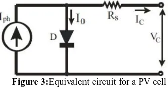
Figure 3:Equivalent circuit for a PV cell
The PV cell output voltage is a function of the photocurrent that mainly determined by load current depending on the solar Irradiation level during the operation.
= + − −
where the symbols are defined as follows: e: electron charge (1.602 × 10⁻¹⁹ C). k: Boltzmann constant (1.38 × 10⁻²³ J/oK). Ic: cell output current, A.
A: curve fitting factor used to adjust the I-V characteristics of the cell Iph: photocurrent, function of irradiation level and junction temperature (5 A). I0: reverse saturation current of diode (0.0002 A).
Rs: series resistance of cell (0.001 Ω).
Tc: reference cell operating temperature (20 °C). Vc: cell output voltage, V.
If the temperature and solar irradiation levels change, the voltage and current outputs of the PV array will follow this change. Hence, the effects of the changes in temperature and solar irradiation levels should also be included in the PV array model.
IV. INVERTERS
The inverter's main functions are: transformation of DC electricity into AC, wave shaping of the output AC electricity, and regulation of the effective value of the output voltage[6][7][8]. The most important features of an inverter for PV applications are its reliability and its efficiency characteristics. They are designed to operate a PV system continuously near its maximum power point. The technology for high-switching-frequency inverters (typically 20 kHz or higher) is made possible by switch-mode semiconductor power devices. PowerMOSFETs and bipolar transistors are used in low-power inverters, whereas thyristors are used in high-low-power applications. Novel devices, such as insulated-gate bipolar transistor (IGBT) inverters are capable of handling several hundred kW, running at frequencies up to 50 kHz. They deliver an AC output wave, which has a form very close to the pure sinusoidal one, with very little filtering at the output. This eliminates the bulky, expensive, and energy-consuming power filters.Inverter interfacing PV module(s) with the grid involves two major tasks. One is to ensure that the PV module(s) is operated at the maximum power point (MPP). The other is to inject a sinusoidal current into the grid.
V. SINUSOIDAL PULSE-WIDTH MODULATION (SPWM)
Copyright to IJAREEIE DOI: 10.15662/ijareeie.2015.0407126 6732
Figure 4:Sinusoidal Pulse-Width Modulation
VI. CASCADED H-BRIDGE MULTILEVEL INVERTER
One more alternative for a multilevel inverter is the cascaded multilevel inverter or series H-bridge inverter [3]. The series H-bridge inverter appeared in 1975. Cascaded multilevel inverter was not fully realized until two researches, Lai and Peng. They presented its various advantages in 1997. Since then, the cascaded multilevel inverter has been utilized in wide range of applications. With its modularity and flexibility, the cascaded multilevel inverter shows superior in high power applications, especially in series and shunt connected FACTS controllers. The cascaded multilevel inverter synthesizes its output nearly sinusoidal voltage waveforms by combining many isolated voltage levels. The diagrammatic representation of cascaded h-bridge multilevel is given in the Figure 5.
Figure 5: Cascaded H-Bridge Multilevel Inverter
The traditional two or three levels inverter does not completely eliminate the unwanted harmonics in the output Waveform[10][11]. Therefore, using the multilevel inverter as an alternative to traditional PWM inverters is investigated. In this topology the number of phase voltage levels at the converter terminals is 2N+1, where N is the number of Cells or dc link voltages[14][15]. In this topology, each cell has separate dc link capacitor and the voltage across the capacitor might differ among the cells. So, each power circuit needs just one dc voltage source. The number of dc link capacitors is proportional to the number of phase voltage levels .Each H-bridge cell may have positive, negative or zero voltage. Final output voltage is the sum of all H-bridge cell voltages and is symmetric with respect to neutral point, so the number of voltage levels is odd. Cascaded H-bridge multilevel inverters typically use IGBT switches.
VII. SIMULATION RESULTS
Copyright to IJAREEIE DOI: 10.15662/ijareeie.2015.0407126 6733
Table 1:Simulation Parameters
Sr.No Items Values
1 PV array parameters Pmax – 60 W
Voc – 22 V Isc - 3.75 Amp
2 LOAD(RL load) P – 1000 W
Q – 500 VAR
3 Inverter switching frequency 5KHz
4 Inverter output frequency 50KHz
Here in this section simulation results and observations of the 5-level and 7-level Cascaded Multilevel Inverter are presented. The different parameters (like voltage, current, THD) in 5-level and 7-level Cascaded Multilevel Inverter are observed. Figure 6 shows the MAT LAB Model of Cascaded 5- Level Multilevel Inverter [13]. Figure 7 shows Multicarrier Pulse Width Modulation for Cascaded 5-Level Multilevel Inverter.
Figure 6: MATLAB model of Cascaded 5- Level Multilevel Inverter
Copyright to IJAREEIE DOI: 10.15662/ijareeie.2015.0407126 6734 Figure 8 shows output voltage and current of Cascaded 5-Level Multilevel Inverter and Figure 9 and Figure 10 shows THD spectrum of voltage and current for Cascaded 5-Level Multilevel Inverter.
Figure 8: Output voltage and current of Cascaded 5-Level Multilevel Inverter
Figure 9: THD spectrum of voltage for Cascaded 5-Level Multilevel Inverter
Figure 10: THD spectrum of current for 5-level Cascaded Multilevel Inverter
Copyright to IJAREEIE DOI: 10.15662/ijareeie.2015.0407126 6735
Figure 11: MATLAB model of Cascaded 7- Level Multilevel Inverter
Figure 12: Output voltage and current of Cascaded 7-Level Multilevel Inverter
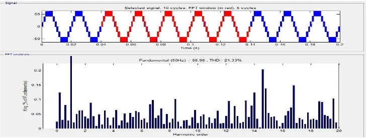
Figure 13 and Figure 14 shows THD spectrum of voltage and current for Cascaded 7-Level Multilevel Inverter.
Copyright to IJAREEIE DOI: 10.15662/ijareeie.2015.0407126 6736
Figure14: THD spectrum of current for 7-Level Cascaded Multilevel Inverter
VII. CONCLUSION
Photovoltaic based applications are increasing day by day.Since most of the electrical application are in AC, so some efficient Power Electronics DC to AC converters are required for converting photovoltaic DC output to AC . Mostly inverters plays a vital role for this conversions. Normally in a Single Phase Full Bridge Inverter output harmonic content is more. Here in this paper a Single Phase Photovoltaic Array fed Cascaded H-Bridge Multilevel Inverter is simulated in MATLAB /Simulink environment. It is clear from the simulation results that by increasing the number of levels in Cascaded H-Bridge Multilevel Inverter there is a significant reduction in the harmonic content of the inverter output.
REFERENCES
[1] Nasr din A. Rahim, Krismadinata Chania,JeyrajSelvaraj Single-Phase Seven-Level Grid-Connected Inverter for Photovoltaic System,IEEE Transactions on Industrial Electronics, VOL. 58, NO. 6, JUNE 2011.
[2] Zameer Ahmad, S.N. Singh, Modeling and Control of Grid Connected Photovoltaic System-A Review International Journal of Emerging Technology and Advanced Engineering, Volume 3, Issue 3, March 2013.
[3] Elena Villanueva, Pablo Correa, Control of a Single-Phase Cascaded H-Bridge Multilevel Inverter for Grid-Connected Photovoltaic Systems, IEEE TRANSACTIONS ON INDUSTRIAL EECTRONICS, VOL. 56, NO. 11, NOVEMBER 2009.
[4] K. Gopala Krishnan, M. Sundar Raj and T. Saravanan, Harmonic Evaluation of Multicarrier PWM Techniques for Cascaded Multilevel Inverter, Middle-East Journal of Scientific Research 20 (7): 819-824, 2014 ISSN 1990-9233.
[5] Sandeep Kumar, Ishtiyaque Ahmed,Application of Multilevel Inverter Using Modulation Technique For Running Induction Motor Smoothly,International Journal of Emerging Technology and Advanced Engineering, Volume 4, Special Issue 1, February 2014.
[6] Martina Calais, Johanna Myrzik,Ted Spoone, Vassilios G. Agelidis,Inverters for Single-phase Grid Connected Photovoltaic Systems - An Overview,2002 IEEE.
[7] Soeren Baekhoej Kjaer, Member, IEEE, John K. Pedersen, Senior Member, IEEE, and Frede Blaabjerg, Fellow, IEEE,A Review of Single-Phase Grid-Connected Invertersfor Photovoltaic Modules,IEEE TRANSACTIONS ON INDUSTRY APPLICATIONS, VOL. 41, NO. 5, SEPTEMBER/OCTOBER 2005.
[8] Michael E. Ropp, Member, IEEE, and Sigifredo Gonzalez,Development of a MATLAB/Simulink Model of a Single-Phase Grid-Connected Photovoltaic System,IEEE TRANSACTIONS ON ENERGY CONVERSION,2009 IEEE.
[9] K Prasada Rao, Dr. Sukhdeo Sao, Dr. JBV Subrahmanyam,Development of A Grid Connected Inverter for Solar PV Systems with Energy Capture Improvement Based On Current Control Strategy,International Journal of Scientific and Research Publications, Volume 3, Issue 4, April 2013.
[10] José Rodríguez, Senior Member, IEEE, Jih-Sheng Lai, Senior Member, IEEE, and Fang Zheng Peng, Senior Member, IEEE,Multilevel Inverters: A Survey of Topologies, Controls, and Applications,IEEE TRANSACTIONS ON INDUSTRIAL ELECTRONICS, VOL. 49, NO. 4, AUGUST 2002.
[11] Gobinath.K, Mahendran.S, Gnanambal.I,New Cascaded H-Bridge Multilevel Inverter With Improved Efficiency,International Journal of Advanced Research in Electrical, Electronics and Instrumentation Engineering Vol. 2, Issue 4, April 2013.
[12] V.Srimaheswaran, R.Uthirasamy,Cascaded Multilevel Inverter for PV Cell Application Using PIC Microcontroller,International Journal of Innovative Technology and Exploring Engineering (IJITEE) ISSN: 2278-3075, Volume-2, Issue-3, February 2013.
Copyright to IJAREEIE DOI: 10.15662/ijareeie.2015.0407126 6737 [14] Jigar Patel, Raj Kapadia, Darshan Patel, Simulation And Analysis Of Cascaded H-Bridge Multilevel Inverter Using Single DC
Source,International Journal of Emerging Technology and Advanced Engineering (ISSN 2250-2459, Volume 3, Issue 4, April 2013). [15] M. Kavitha, A. Arunkumar, N. Gokulnath, S. Arun and A. Ragavendiran,Single Phase Pv Cell Fed H- Bridge Multilevel Inverter Using Boost
Converter,International Journal of Scientific & Engineering Research, Volume 4, Issue 5, May-2013 ISSN 2229-5518.
[16] K.Surya Suresh and M.Vishnu Prasad,PV Cell Based Five Level Inverter Using Multicarrier PWM,International Journal of Modern Engineering Research (IJMER)Vol.1, Issue.2, pp-545-551 ISSN: 2249-6645.
[17] Divya Subramanian, Rebiya Rasheed,Five Level Cascaded H-Bridge Multilevel Inverter Using Multicarrier Pulse Width Modulation Technique,International Journal of Engineering and Innovative Technology (IJEIT) Volume 3, Issue 1, July 2013 ISSN: 2277-3754.