PSO-BASED FAST OPTIMIZATION ALGORITHM FOR BROADBAND ARRAY ANTENNA BY USING THE CUBIC SPLINE INTERPOLATION
J.-F. Li, B.-H. Sun, and Q.-Z. Liu
National Key Laboratory of Antennas and Microwave Technology Xidian University
Xi’an, Shaanxi 710071, China
L. Gong
Dalian Air Traffic Management Station of Civil Aviation of China Dalian 116033, China
Abstract—This paper describes a fast pattern synthesis method for a broadband array antenna using the particle swarm optimization (PSO) and cubic spline interpolation (CSI). Being an indispensable part of a high speed space-division communication system, the array antenna operates in a wide frequency band (200–400 MHz) and has stable patterns with 60-degree half power beam width (HPBW) in the whole frequency band. Firstly, by establishing a versatile objective function, the complex excitations of the circular array at the selected seven frequency points are determined via the PSO algorithm. Then, the complex excitations of the circular array at arbitrary frequency points in the whole working frequency band are calculated effectively using the CSI method. A uniform circular array with six broadband dipole elements is examined. The broadband patterns with 60-degree HPBW and the accuracy of the interpolation method are demonstrated.
1. INTRODUCTION
Division Multiple Access (TDMA), and Code Division Multiple Access (CDMA). Recently, Space Division Multiple Access (SDMA) [1, 2] has received more and more attentions due to its following advantages: the base station antenna of SDMA is array antenna, whose coverage area is much greater than that of other single antenna; interferences coming from other systems can be reduced significantly. SDMA employs fixed beam servicing to different users, and can be flexibly used in different coverage area. The space is divided into six coverage sectors in the presented SDMA system. As a result, the base station antenna should have a 60◦ half power beam width (HPBW) and adaptive main lobe direction. Many array antenna pattern synthesis methods have been studied [3, 4, 7, 8, 10, 11], however, most literatures mainly focus on single frequency or narrowband optimization. In modern communication system, frequency hopping spread spectrum is usually adopted to further increase the data transmission rate. That requires a broadband array antenna which can cover one or two times frequency band and even wider. However, the question of optimizing the broadband antenna array has not yet to be determined. Finding a fast and effective synthesis method now comes to be a new difficulty challenge.
In this paper, we present a novel method for optimization of broadband antenna array, which seeks the complex excitations (amplitudes and phases) of circular array elements in the working frequency band (200–400 MHz) for finding an adaptive shaped beam with a 60◦ HPBW. First, the particle swarm optimization algorithm is used to maximize the antenna gain in the main direction of desired signal and form 60◦ space coverage for HPBW. Then, the cubic spline interpolation (CSI) method is utilized to obtain the optimized complex excitations at arbitrary frequency points within the working frequency band.
2. PSO ALGORITHM
The PSO algorithm randomly initializes the locations and velocities of particles in theD-dimensional search space. Each particle flies to the target area and adjusts its position according to its own experience and the best experience of its topological neighbour. The position and velocity of the i-th particle are represented as
Xi = (xi1, xi2, . . . , xiD) and Vi = (vi1, vi2, . . . , viD), respectively.
The personal previous position is recorded and expressed as Pi = (pi1, pi2, . . . , piD). The index of the best particle among all the particles
is represented by the symbolg. The positions and velocities of particles are updated according to the following equations:
vid=w∗vid+c1∗rand()∗(pid−xid) +c2∗rand()∗(pgd−xid) (1)
xid=xid+vid,1≤d≤D (2)
where w is the inertia weight. c1 and c2 are acceleration constants,
both of which are positive. rand() denotes a random number in the range [0, 1]. The first part of formula (1) is the initial velocities of particles; the second part is “cognition”, which expresses the cogitation of particles; the third part is “social”, which expresses the registration of message and cooperation among particles.
3. ARRAY ANTENNA OPTIMIZATION
3.1. Objective Function
For a practical problem, an objective function must be defined to link the design requirements with the optimization algorithm. In the proposed SDMA communication system, the maximum gain of the desired signal direction and the 60◦ HPBW coverage are the key factors. By the way, a low side lobe level (SLL) is also needed to reduce the interferences from undesired directions. Considering all the above factors, the objective function is defined as follows:
f = c1min{1/G0}+c2min{|G0−Gmax|}+c3min{max{SLL}}
+c4min{|0.5∗G0−G(phamax±30)|} (3)
where G0 is the gain of the desired signal direction, Gmax is the
maximum gain for each solution. SLL and phamax denote the side lobe level and the direction of the desired signal, respectively. The constants c1,c2, c3 and c4 are the adjustable weights for each part of
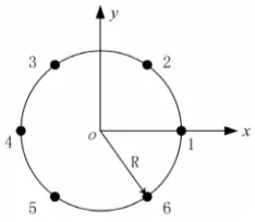
Figure 1. Geometry of a 6-element circular array.
3.2. 6-element Circular Array Antenna
The basic geometry of a 6-element circular array antenna is shown in Fig. 1. The array is composed of six broadband dipoles [13], which are identical and perpendicular to the array plane. The array factor of the circular array is given in the following:
AF(θ, ϕ) =
N
n=1
Inej[kasinθcos(ϕ−ϕn)+αn] (4)
whereN is the number of the circular array elements,θ∈[−π/2, π /2],
ϕ ∈ [0,2π], φn = 2(n−1)π/N. In, αn are amplitude and phase of
each element, respectively. X = (I1, I2, . . . , IN, α1, α2, . . . , αN) is the
vector variable of PSO. For anN-element circular array antenna,Xis 2N dimensional vector.
Due to the symmetrical configuration of the array, if the required radiation pattern is also symmetrical, only half of the complex excitation coefficients have to be optimized. A smaller excitation vector consequently leads to a faster code.
4. CUBIC SPLINE INTERPOLATION
selected, which distribute in the working frequency band. Secondly, the amplitudes and phases are optimized using the proposed method in Section 2 at each selected frequency point, respectively. Finally, the amplitudes and phases at arbitrary frequency points are calculated out using the cubic spline interpolation method described as follows.
Cubic spline interpolation (CSI) is an effective method that offers true continuity between the segments [14, 15]. We take a series of points [xi, yi] (i= 0,1,2, . . . , n) for the functiony=f(x). That makesn+ 1 points and nintervals between them. The assumed form of the cubic polynomial curve fit for each segment is:
si(x) =ai(x−xi)3+bi(x−xi)2+ci(x−xi) +dii= 0,1,2, . . . , n (5) The routine fitsnequations subjecting to the boundary conditions ofn+1 data points. The liner boundary conditions are given as follows: 1) The cubic polynomial matches the values of the table at both ends of the interval:
si(xi) =yi, si+1(x) =yi+1 (6)
2) In order to make the interpolation as smooth as possible, the first and second derivatives should be continuous:
si−1(xi) =si(xi) si−1(xi) =si(xi), i= 1,2, . . . , n−1. (7)
3) There are some standard choices in the following:
s0(x0) = 0, sn−1(xn) = 0 (natural) (8) s0(x0) = f(x0), sn−1(xn) =f(xn) (clamped) (9)
The choice of (8) or (9) depends on the practical applications, and the natural condition is used here.
(a) (b)
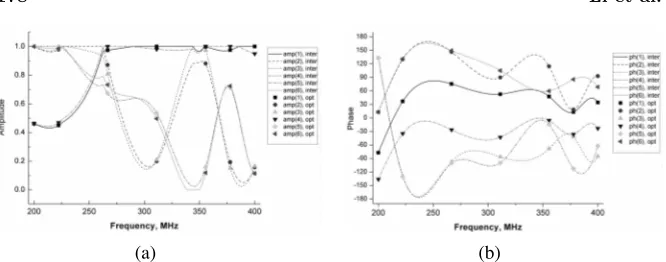
Figure 2. Complex excitations of circular array antenna. (a) Amplitudes of the circular array elements. (b) Phases of the circular array elements.
5. ANTENNA ARRAY DESIGN AND NUMERICAL RESULTS
A 6-element circular array antenna working in a broad-band frequency (200–400 MHz) is studied here. The radius of the circular array R is selected as 0.32 meter. The desired user direction is considered at θ = 90◦ and φ = 0◦. The HPBW is designed as 60◦ to suit the requirements of SDMA.
The performance of the presented arrays is optimized by the PSO algorithm using FORTRAN code program. The array elements are identical and horizontal omnidirectional. The mainlobe may points to the arbitrary direction, and the radiation pattern is only symmetrical in the specifically condition. Thus, all complex excitations coefficients are selected to be optimized. The vector variable for the PSO algorithm is X= (I1, I2, I3, I4, I5, I6, α1, α2, α3, α4, α5, α6). The inertia weight w
is set to 0.7. The acceleration constants c1 and c2 are both 2.0. The
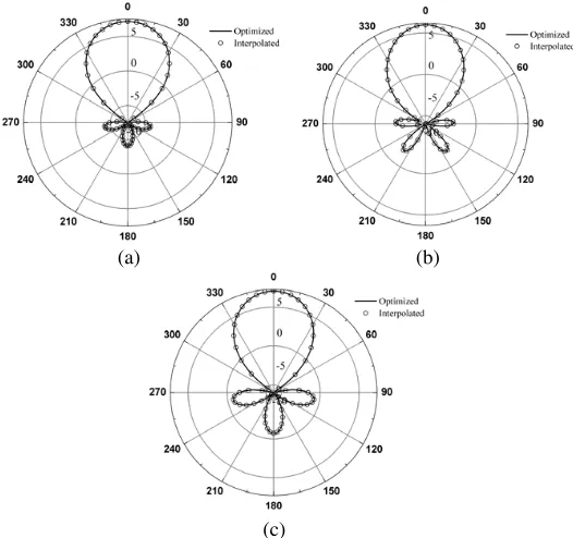
variation range ofI is from 0 to 1.0 andα is from−180 to 180 degree. Seven frequency points including starting and ending frequency and another five points among them are selected for optimization. The radiation pattern of the starting and ending frequency are depicted in Figs. 3(a) and 3(b). From the two pictures, it can be found easily that the optimized array antenna has a radiation pattern with 60◦ HPBW and the main lobe direction points to the desired user. Furthermore, the SLL of the presented array antenna is quite low. The radiation patterns of the other five points are similar to Fig. 3 and are not given here for the sake of simplicity.
(a) (b)
(c)
Figure 3. Radiation patterns for 6-element circular array antenna, (a) 200 MHz, (b) 400 MHz, (c) 310 MHz.
excitations at arbitrary frequency points in the working frequency band. Figs. 3(a) and 3(b) give comparisons between the optimized results and the interpolated results at 200 MHz and 400 MHz. From the figures, we can see that both of them have preferable good agreement. In order to further prove the correctness and efficiency of the CSI method, arbitrary sampling frequency points are chosen, and taking 310 MHz as an example. Good agreement is also achieved between optimization and interpolation, as shown in Fig. 3(c).
6. CONCLUSION
are obtained. This method can be effectively adopted in smart antenna system, especially in space-division communication system.
REFERENCES
1. Frank, B. G.,Smart Antennas for Wireless Communications with
MATLAB, McGraw-Hill, New York, 2005.
2. Nishimori, K. and K. Cho, “A novel SDMA configuration using smart antenna adopting vertical pattern and polarization control,” Vehicular Technology Conference, Vol. 2, 871–875, 2003.
3. Mahmoud, K. R., M. I. El-Adawy, R. Bansal, S. H. Zainud-Deen, and S. M. M. Ibrahem, “Analysis of uniform circular arrays for adaptive beamforming applications using particle swarm optimization algorithm,”International Journal of RF and Microwave Computer-Aided Engineering, Vol. 18, No. 1, 42–52, January 2008.
4. Peter, J. B. and A. B. Constantine, “Minimum sidelobe levels for linear arrays,”IEEE Transactions on Antennas andPropagation, Vol. 55, No. 12, 3442–3449, 2007.
5. Kennedy, J. and R. C. Eberhart, “Particle swarm optimization,” Proceedings of IEEE International Conference on Neural Net-works, Vol. 4, 1942–1948, Perth, Wash, Australia, November 1995. 6. Robinson, J. and Y. Rahmat-Samii, “Particle swarm optimization in electromagnetics,” IEEE Transactions on Antennas and Propagation, Vol. 52, No. 2, 397–407, 2004.
7. Lee, K. C. and J. Y. Jhang, “Application of particle swarm algorithm to the optimization of unequally spaced antenna arrays,” Journal of Electromagnetic Waves andApplications, Vol. 20, 2001–2012, 2006.
8. Chen, T. B., Y. L. Dong, Y. C. Jiao, et al., “Synthesis of circular antenna array using crossed particle swarm optimization algorithm,” Journal of Electromagnetic Waves andApplications, Vol. 20, 1785–1795, 2006.
9. Liu, X. F. Y. B. Chen, Y. C. Jiao, et al., “Modified particle swarm optimization of patch antenna design based on IE3D,” Journal of Electromagnetic Waves andApplications, Vol. 21, 1819–1828, 2007.
11. Khdier, M. M. and C. G. Christodoulou, “Linear array geometry synthesis with minimum sidelobe level and null control using particle swarm optimization,” IEEE Transactions on Antennas andPropagation, Vol. 53, No. 8, 2674–679, March 2005.
12. Lim, T. S., V. C. Koo, H. T. Ewe, and H. T. Chuah, “A SAR autofocus algorithm based on particle swarm optimization,” Progress In Electromagnetics Reseach B, Vol. 2, 27–60, 2008. 13. Lilley, D. G.Numerical Methods, Stillwater, OK, 2002.
14. Li, J. F., B. H. Sun, H. J. Zhou, and Q. Z. Liu, “Novel center-fed cage antenna using the composite structure,” Journal of Xidian University, Vol. 35, No. 5, 889–893, 2008.