Fuzzy Based Phase-Shift PWM Controller for Four Level Hybrid Converter
S. Sreenu & K.R. Anugna Hinduja
Assistant Professor, BVRIT, Hyderabad, T.S, INDIA
Abstract-This paper introduces an advanced four-level hybrid converter topology which is made out of eight switches and one flying capacitor per stage. The working standard is presented and stage moved heartbeat width balance is utilized to control this converter. A detailed examination of the normal streams through the flying capacitor and unbiased purposes of the dc-interface is displayed. In view of the examination, it can be inferred that the voltages over the flying capacitor and dc-connect capacitors can be normally adjusted under perfect and unfaltering state condition. Simulation model is developed to approve the proposed topology and modulation technique.
Index terms- Multilevel converters, VSC, Hybrid model, flying capacitor, Voltage balancing
I. INTRODUCTION
Among the existing multilevel converters, diode-cinched, flying-capacitor, what's more, fell H-connect multilevel converters are three traditional multilevel topologies which are the most broadly utilized as a part of the business. Both inactive devices (diodes what's more, capacitors) and dynamic switches are utilized for bracing in this topology thus it can be viewed as a half breed cinched converter. At low voltage, there is a solitary topology that commands the market: the voltage-source two-level inverter. Nonetheless, at medium and high voltages, the circumstance is totally unique. As a result, for high-control applications, it is conceivable to utilize coordinate converters (cyclo-converters) or circuitous converters (with current or voltage dc connect). The primary impediment of this topology is an expansive number of cinching switches and capacitors are received, which makes it hard to be marketed and utilized as a part of reasonable applications.
Pulse width adjustment (PWM) VSCs has supplanted thyristor-based converters in an extensive variety of utilizations. This is to a great extent because of generous framework favorable circumstances, for example, expanded accessibility because of ride through ability as well as a repetitive converter
configuration, definitely enhanced dynamic
execution, expanded working reach, lessened line music, what's more, a customizable power factor at the purpose of normal coupling. It is involved various fell half-bridges without transformer, so the yield voltage can reach to several kilovolts. Five-level dynamic unbiased point cinched (ANPC) converter is another alluring half breed clasped converter which is more reasonable for superior medium-voltage motor drives.
Keeping in mind the end goal to stay away from the arrangement association of two switches in the five-level ANPC converter, this paper shows a novel four-level cross breed clasped converter for medium-voltage engine drives.
This four-level mixture clipped topology can likewise be respected as an alteration of four-level flying-capacitor topology. The high-voltage flying flying-capacitor close to the dc-connect is supplanted by two clipping switches, consequently the aggregate size and weight can be decreased.
II. SYSTEM DESCRIPTION
Switches S1 and S7, switches S6 and S8, switches S2 furthermore, S5, and switches S3 and S4 ought to be worked in a reciprocal way, separately. 2) Switches S1 and S8 ought to be worked in stage, while switches S7 and S6 ought to likewise be worked in stage. On the off chance that S1 and S6 are exchanged ON in the meantime, either S2 or S5 will withstand a twofold voltage worry of 2E.
In view of the above working principles, each stage can yield four voltage levels with eight unmistakable exchanging states. Extraordinary exchanging states impacts affect the flying capacitor also, DC-interface capacitors, as appeared in Fig. 3, where icf and (iN1, iN2) are the streams streaming out of the flying
capacitor Cf and neutral points (N1, N2),
individually, io is the yield current.
Figure 1: proposed four-level hybrid-clamped converter
III. VOLTAGE BALANCING
Considering a solitary stage and characterizing the exchanging capacity of switch Sx is Sfx, where x speaks to 1– 8, the momentary yield voltage level Vo can be composed as the total of voltages crosswise over switches S1, S2 , and S3:
Vo = (Sf 1 + Sf 2 + Sf 3)E
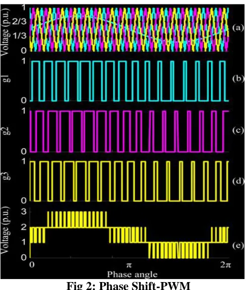
Above equation demonstrates that the yield voltage level is resolved by the whole of the exchanging capacities Sf1, Sf2, and Sf3.Additionally, switches S1, S2 , and S3 are autonomous of each other with the goal that established PS-PWM can be utilized to
Fig 2: Phase Shift-PWM
The aggregate dc-interface voltage is consistent. At that point the impact of the dc-interface voltage swell on the nonpartisan point possibilities can be disposed of; the capacitors in the dc-interface have a similar capacitance furthermore, trademark, i.e., Cd1 = Cd2 = Cd3; the yield voltage and current are absolutely sinusoidal and symmetrical; the transporter recurrence is substantially higher than the major recurrence with the goal that the reference voltage and stage current can be considered as a consistent in a transporter period.
For the flying capacitor Cf, the heap current streams out of it whenever S3 and S5 are exchanged ON and into it when S2 and S4 are exchanged ON. So the prompt flying capacitor current icf can be composed as
icf = (Sf 3 − Sf 2 )io
On the off chance that E is chosen as the base voltage esteem, at that point the scope of the yield stage voltage is in the vicinity of 0 and 3. In the PS-PWM, the reference voltage for switches S1, S2, and S3 is the same and in the vicinity of 0 and 1. It is accepted
that the stage voltage and current are impeccable sinusoidal and symmetrical in perfect conditions, so the reference voltages uref and stage current io can be characterized as takes after:
uref = (m*sinɵ + 1)/2
io = Im sin(ɵ− ϕ)
Where m is the regulation file, θ is the stage point (θ = ωt, where ω is the rakish recurrence), Im is the amplitudes of the stage current, and ϕ is the power factor edge. The tweak list m is in the vicinity of 0 and 1 with the goal that the scope of uref is moreover in the vicinity of 0 and 1. At that point, the obligation proportion of Sf1, Sf2, and Sf3 of every a transporter period can be composed as
d1 = d2 = d3 = uref
IV. SIMULATION RESULTS
To confirm the legitimacy of the proposed topology and regulation strategy, a low power three-stage four-level half and half braced converter simulation circuit was built up with MATLAB/simulink software, as appeared in Fig. 3. Each stage leg contains a flying capacitor, eight IGBTs, and the relative entryway drivers, voltage/ebb and flow test, furthermore, A/D changing over circuits, and three dc-interface capacitors. The dc-interface capacitors of three stages are parallel associated.
Fig 4: Controller subsystem with fuzzy Controller
Fig 5: Load Current
Fig 6: DC-Link voltage (Vdc)
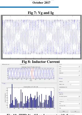
Fig 7: Vg and Ig
Fig 8: Inductor Current
Fig 10: THD % of Load current with fuzzy controller
V. CONCLUSION
A novel four-level hybrid clamped converter topology is presented in this paper. The exchanging capacity model of normal streams through the flying capacitor and unbiased focuses is dissected, which shows that the voltages over the flying capacitors and the dc-connect capacitors can be normally adjusted under perfect and enduring state condition utilizing PS-PWM. Test comes about have shown the legitimacy of this topology what's more, regulation strategy.
REFERENCES
[1] F. Peng, “A generalized multilevel inverter topology with self voltage balancing,” IEEE Trans.
Ind. Appl., vol. 37, no. 2, pp. 611–618,
[2] R. Marquardt and A. Lesnicar, “A new modular voltage source inverter topology,” in Proc. Eur. Power Electron. Conf, [CD-ROM], 2003.
[3] M. Guan and Z. Xu, “Modeling and control of a modular multilevel converter-based HVDC system
under unbalanced grid conditions,” IEEETrans.
Power Electron., vol. 27, no. 12, pp. 4858–4867, Dec. 2012.
[4] J. Pou, R. Pindado, and D. Boroyevich, “Voltage-balance limits in fourlevel diode-clamped converters with passive front ends,” IEEE Trans. Ind. Electron., vol. 52, no. 1, pp. 190–196, Feb. 2005.
[5] K.Wang, Y. Li, Z. Zheng, and L. Xu, “A novel hybrid-clamped four-level converter,” in Proc. IEEE Appl. Power Electron. Conf., 2012, pp. 2442–2447.
S. SREENU was born in Nagarjuna Sagar, India, in 1989. He received the B.Tech and M.Tech. Degrees from JNTUH University, India, in 2010 and 2014, respectively, and currently working as an Assistant Professor at “Dr.B.V.Raju Institute of Technology-Autonomous”,Narsapur, Telangana, India.