Simulation of DC Motor Control Strategy for
PWM Rectifier with Power Factor Correction
RACHAKAT LA BHAVANA M-tech Student Scholar
Department of Electrical & Electronics Engineering, ARJUN College of T echnology & Sciences Engineering College,
HAYAT H NAGAR; Rangareddy (Dt); T elangana, India.
ROSAIAH MUDIGONDALA Assistant Professor
Department of Electrical & Electronics Engineering, ARJUN College of T echnology & Sciences Engineering College,
HAYAT H NAGAR; Rangareddy (Dt); T elangana, India
ABSTRACT: Power electronics equipments become more widely used. Unfortunately, the standard diode/Thyristor bridge rectifiers at the input side cause several problems as: Low input power factor, high values of harmonic distortion of ac line currents, and harmonic pollution on the grid. In recent years, the research interest in the area of PWM rectifiers has grown rapidly. The PWM rectifier offers several advantages such as: control of DC bus voltage, bi -directional power flow, unity power factor, and sinusoidal line current. Many pulse-width modulation (PWM) techniques have been adopted for these rectification devices to improve the input power factor and shape the input current of the rectifier into sinusoidal waveform. The phase and amplitude control (PAC) seems to be the most simple structure and provides a good switching pattern, but the dc offset on input current of the rectifier during transient state deteriorates the control system stability. The current regulating fashion in synchronous frame has the advantages of fast dynamic current response, good accuracy, fixed switching frequency and less sensitive to parameter variations. This project analyzes the principle of PWM rectifier, and presents a unity power factor control method of PWM rectifier. Controller used double closed-loop PI control, which inner uses three-phase input current control method controlled by unity power factor and outer controls the output DC voltage of rectifier. The proposed concept can be
implemented with DC motor using
MATLAB/SIMULINK software.
Keywords- PWM, rectifier, unity power factor, filter
I INTRODUCTION
Since the rectifier consisted of diode or thyristor is easy to control and reliab le, it is widely used in industry. However, the input current of this rectifier contains a large number of harmonics, wh ich has become to the main source of grid. In addition, this rectifier also has the issue about low power factor. PWM rectifier does not produce harmonics on the gain, while the input power factor can be controlled and the output DC voltage can be adjustable, is a high performance fairing. In this paper, a PWM rectifier is studied, wh ich focus on an unity power factor control
method. The result of the simulation and experiment show the feasibility and effectiveness of the
method[1].
II PWM RECTIFIER AND ITS UNITY POWER FACTOR CONTROL METHOD S ELECTING A TEMPLATE
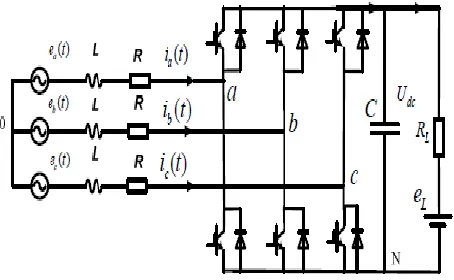
Figure 1 shows the structure of the PWM rectifier.
is the three phase voltages. L is the support filtering inductance of the AC side voltage. R is the equivalent resistance of the system. C is the support capacitance of the DC side voltage.RL is the resistive load. eLis the load force.
Fig.1 T he structure of the PWM rectifier
the output DC voltage of rectifier, to control the power of the rectifier[2].
Fig.2 T he direct power control method block diagram of the PWM rectifier
This control method of the control system is implemented as follows:
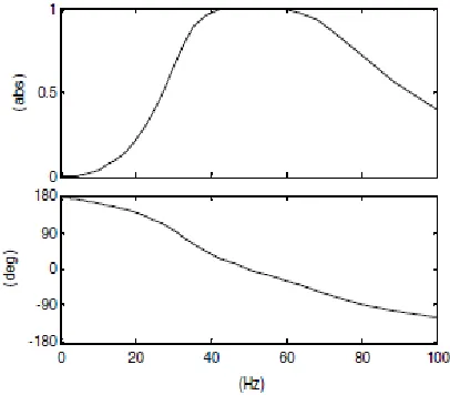
1) Detection the instantaneous fundamental component of the voltage and current. Using the second-order Butterworth digital filtering algorith m of equation 1, the amplitude, and phase and frequency characteristics of this filter is shown in figure 3.
Fig.3 T he amplitude, phase and frequency characteristics of Butterworth band-pass filter
Fro m which we can see, amplitude of the fundamental co mponent part of the signal does not decay, the phase does not shift, which on the basis of ensuring filters the DC co mponent of the input signal and high harmonics.
The sampling frequency of the discrete formu la is 5000Hz, and filter quality factor o f the design is 1 [3].
2) Calculate the instantaneous active power and reactive power. Obtain the input active power and reactive power via the the calculation of equation 2 and equation 3.
3) Calculate the average active power, reactive power and DC voltage in each cycle. Using the average formula of equation 4 to obtain the input active power, reactive power and dc capacitor voltage of the rectifier.
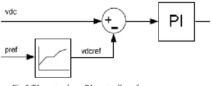
4) For reactive power q, the use of the inner PI control algorithm make the input reactive power of the rectifier is zero, which achieves the unity power factor input. The block diagram to ach ieve the inner PI control algorithm is shown in Figure 4.
Fig.5 T he outer loop PI controller of power 6) Obtain the real-time phase of the grid. The three-phase fundamental voltage obtained in Step1) can obtain the real time phase information of the grid by using formula 5, formula 6 and formula 7.
7) Obtain the three-phase output current reference value. Use formula 8 to obtain the three-phase output current reference value.
The output of PWM signal. Switch the output current reference value of rectifier to the switching time of each switch device[5].
III DC MOTOR
DC motors are preferred where wide speed range control is required. Phase controlled converters provide an adjustable dc voltage from a fixed ac input voltage. DC choppers are also providing dc output voltage fro m a fixed dc input voltage. The use of phase controlled rectifiers and dc choppers for the speed control of dc motors modern industrial controlled applications. DC drives are classified into the following methods:
A.DC Motor Control System
Figure 4 shows the schematic arrangement of a two quadrant controller’s dc drives system .The figure showing the 2 control loops. First one is outer speed control loop and the other one is inner current control
prominent than triangular wave then the power gadget is switched on.
IV MATLAB/SIMULINK RESULTS
Fig 6 Matlab/simulation circuit of T he structure of the PWM rectifier
Fig 7 simulation wave form the input voltage, input current and output voltage waveform when the rectifier work in rectifying
mode
Fig 8 the input voltage and input current waveform when the rectifier work in the inverter mode
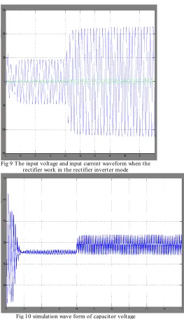
Fig 9 T he input voltage and input current waveform when the rectifier work in the rectifier inverter mode
Fig 11 Matlab/simulation circuit of T he structure of the PWM rectifier with DC Motor
Fig 12 simulation wave form of the PWM rectifier with DC Motor speed
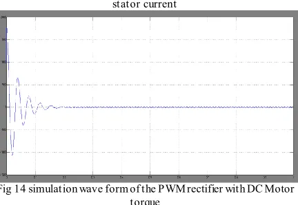
Fig 13 simulation wave form of the PWM rectifier with DC Motor stator current
Fig 14 simulation wave form of the PWM rectifier with DC Motor torque
CONCLUSION
This paper analyzes the principle of PWM rectifier, and presents a input unity power factor control method of PWM rectifier. The result of the simu lation and experiment verify the feasibility and effectiveness of the method. The proposed method DC Motor characteristics can be speed, current and torque be studied
REFERENCES
[1] The Research and Development of the High Performance Dual PWM AC Drives. PhD thesis. 1997
[2] Zhang Chongwei, Zhang Xing. PWM Rectifier and its Control.Beijing Mechanical Industry Press. 2003.
[3] Wang Zhaoan, Zhang Ming xun, Power Electronic Equip ment Design and Application Manual [M].Beijing Mechanical Industry Press. 2002:675-676.
[4] Wang Jiuhe. The Non-linear Control of Voltage-type PWM rectifier.Mechanical Industry Press. 2008. [5] Study of the Control Techniques of System Waveform of High Power and High Frequency PWM Reversible Rectifier. Ph D thesis.Huazhong University of Science and Technology, 1997
Author’s Profile :
(2009 – 2013) From PRRM Engineering College; JNTUH Shabad, Rangareddy(dist). Pursuing M.Tech In Power Electronics And Electrical Drives In Arjun college of Technology And Sciences JNTUH.
Rosaiah Mudigondla Working As