Controlling of Two Wheeled Self Balancing
Robot using PID
Eldhose P Kunnel1, Dijoy Johny2, Anuja Jacob3, Elizabeth Paul4
UG Student, Dept. of EEE, Mar Athanasius College of Engineering, Kothamanglam, Kerala, India1
UG Student, Dept. of EEE, Mar Athanasius College of Engineering, Kothamanglam, Kerala, India2
UG Student, Dept. of EEE, Mar Athanasius College of Engineering, Kothamanglam, Kerala, India3
Professor, Dept. of EEE, Mar Athanasius College of Engineering, Kothamanglam, Kerala, India4
ABSTRACT: Self balancing robot is essentially an inverted pendulum. It can balance better if centre of mass is higher relative to the wheel axels. A higher centre of mass means a higher moment of inertia which means a lower angular acceleration. It act as a robot which can balance by itself. The experiment requires Arduino, MPU6050 board, L293D driver module. Balancing of the robot can be done with help of feedback and a correction element. Feedback element is the MPU6050 board which tells the Arduino about current orientation of the robot. Experiment mainly uses PID controller, having gains Kp, Kiand Kd. PID provides correction between desired value and actual value. The difference
between input and output is called error. The PID controller reduces the error to smallest value possible by adjusting the output. MU6050 reads the current tilt of robot and feeds it to the PID algorithm, which performs calculations to control motor and keep the robot in upright position.
KEYWORDS: Inverted Pendulum, Calibration, PID, MPU6050
I.INTRODUCTION
Two wheeled balancing robot is a classic engineering problem based on inverted pendulum and is much like trying to balance a broom on the tip of your finger. This challenging robotics, electronics, and controls problem is the basis of my study for this project.
The word balance means the inverted pendulum is in equilibrium state, which its position is like standing upright 90 degrees. However, the system itself is not balance, which means it keeps falling off, away from the vertical axis. Therefore, a gyro chip is needed to provide the angle position of the inverted pendulum or robot base and input into the microcontroller, which the program in itself is a balancing algorithm. The experiment mainly uses PID controller, having gainsKp, Kiand Kd. PID provides correction between desired value and actual value. The difference between input and
output is called error. The PID controller reduces the error to smallest value possible by adjusting the output. The MPU6050 reads the current tilt of the robot and feeds it to the PID algorithm, which performs calculations to control the motor and keep the robot in upright position.The microcontroller will then provide a type of feedback signal through PWM control to the H-bridge circuit to turn the motor clockwise or anticlockwise, thus balancing the robot.
[2]The system architecture comprises a pair of DC motor and an Arduino microcontroller board; a single-axis gyroscope and a 2-axis accelerometer are employed for attitude determination. In addition, a complementary filter is implemented to compensate for gyro drifts. Electrical and kinematic parameters are determined experimentally; PID and LQR-based PI-PD control designs, respectively, are performed on the linearized equations of motion.[6]The types of control is categorized as linear and non-linear control. In some instances, the linear control is sufficient to control a system. One of the most widely used is the Proportional Derivative Integral controller or better known as the PID controller [10].
II.SYSTEMCONFIGURATIONANDOPERATINGPRINCIPLE
Self Balancing Robot is a robot which balances by itself. The Self Balancing Robot is similar to an inverted pendulum. The pendulum must remain in the vertically upright position even if it undergoes a certain force.
A. Block Diagram And Operating Principle–
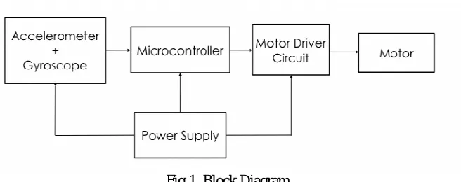
Fig 1. Block Diagram
Fig 1 shows the block diagram for controlling of two wheeled self balancing robot using PID, in order to maintain a vertical upright position even in the presence of a disturbing force. The angle of tilt with respect to the reference axis caused by the external force need to be measured. This is done by the accelerometer and gyroscope. This information is fed to the microcontroller generates control signals to activate the motor driver circuit so as to drive the motor either forward or backward, to maintain balance.
The physics for this robot is simple: the robot stands in two points lined with the wheel, and it tends to fall vertically. The movement of the wheel in the direction of the falling raises the robot to recover the vertical position. The vehicle attempts to correct for an induced lean angle by moving forward or backward, and the goal is to return itself to vertical or at least not fall over. For that objective we have two things to do; on one hand we have to measure the angle of inclination (Roll) of the vehicle, and on the other hand we have to control the motors for going forward or backward to make that angle θ,
maintaining a vertical position.
B. Balancing Theories
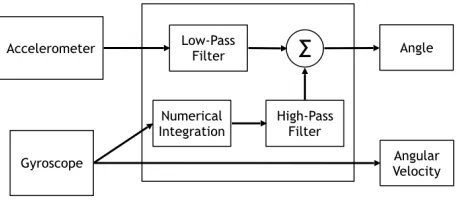
The accelerometer and gyroscope both have its advantages and disadvantages. The accelerometer can measure the force of the gravity, and with that information we can obtain the angle of the robot. The problem of the accelerometer is that it can also measure the other forces on the vehicle, so it has lot of error and noise.
III. EXPERIMENTAL SETUP AND WORKING
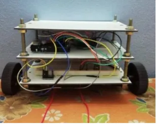
Fig 2. Experimental Setup
Fig 2.shows the experimental setup for controlling of two wheeled self balancing robot using PID. We are going to see how self balancing robot works. It simply a robot which balance by itself. The self balancing robot is similar to an inverted pendulum. The pendulum must remain in the vertically upright position even it undergoes a certain force.
When the robot is about to fall the wheels must move in the inclined direction with a speed proportional to angle of fall to correct the inclination. This can be done by measuring the angle of tilt. This is done by a gyroscope and accelerometer which tells the correct orientation of the robot. With the help of feedback element this is fed back to the Arduino and a correcting element, the motor and the wheels together prevents the robot from falling. This ensures the robot stands erect.
The PID controller provides a correction between the desired (input) and actual (output) values. The difference between the input and output is called as an error. The PID controller reduces the to the minimum possible value by continually adjusting the out put. The gyroscope and accelerometer determines the tilt of the robot and feeds it to the PID which now control the motor and holds the robot in upright position.
A. Calibration of MPU6050
Fig 3. Experimental Setup for Calibration of MPU6050
Whenever an external disturbing forces comes into play, new set of offset values with respect to reference axis will be formed. A feedback mechanism is provided which compares the new set of values with initial reference values. Thus the position of robot from balancing position is determined. The angle of tilt can be corrected by controlling dc gear motors and thereby maintaining balance.
B. PID Tuning
Tuning is a process in which certain parameters of a device like proportional gain (Kp), integral gain (Ki) and derivative
gain (Kd) are varied to get appropriate results. The proportional gain Kp constant (Kp)is directly proportional to error. A
small change in (Kp)would automatically be reflected in the error values. Small values of (Kp)would be insufficient,
since the controller might not be able to minimise the error and quickly respond to the changes affecting the system. Large values of (Kp)cause the system to be unstable and result in weird oscillations. The integral gain(Ki) accounts for
the past values of the error and integrates them over time to produce the Kiterm. i.e., the integral term lets the controller
to take up all the errors that are accumulating over time and creates the next Kivalue depending on the previous errors.A
larger Ki value results in higher growth of the accumulated error.The derivative gain Kd estimates the future trend of the
error based on the current rate of change of error. i.e., it controls the error by analysing the rate of change of error. This helps to dampen the system, thus improving stability. The change in the system will be rapidly evident with smaller change in Ki
There are many ways by which Kp, KiandKdvalues of the system is tuned one of which is manual tuning through which
stability can be easily achieved. Initially the Kp, KiandKdvalues are set to zero. Then Kpvalue is increased from zero till a
point where the system starts to oscillate from its mean position. And as the Kpvalue is increased, it was seen that
response of the system increase gradually. Keeping the Kpvalue a constant the Kivalue is then increased till a point where
it is seen from the system that a small inclination towards a direction tends to accelerate the vehicle towards that direction. When the Kpand Kivalues are properly obtained, then the Kdvalue is increased. The Kdvalue is increased such
that rapid acceleration is reduced considerably. Proper KDvalue results in lesser overshoots and oscillations. After
obtaining the rough Kp, Kiand Kdvalues a fine tuning is done. The above steps are repeated a number of times to obtain
the best combination of gain values.
IV. RESULT AND DISCUSSION
Fig 4. Complimentary Filter
Fig 5. PID Tuned Values
Controlling of two wheeled self balancing robot using PID done by trial and error method by continuously tuning Kp,Kiand Kd. Kp= 23, Ki=38and Kd=1.5as shown in Fig 5, at this value two wheeled self balancing robot is fully
controlled
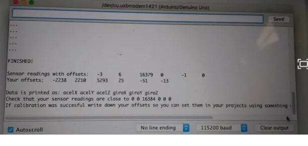
Fig 6. Offset Values
Fig 6.shows the offset values for controlling of two wheeled self balancing robot using PID obtained from calibration of MPU6050. As it is the offset values or reference values with respect to ground plane.
V. CONCLUSIONS
A two wheeled self balancing robot based on the inverted pendulum model principle has been successfully constructed. The control strategies employed at balancing the robot include calibration of MPU6050 and PID tuning. Firstly MPU6050 is calibrated with respect to ground plane to obtain 6 set of offset values from accelerometer and gyroscope. Secondly PID tuning is done by trial and error method to make robot in standstill position. A detailed study of Balancebot makes it clear that PID algorithm can be used to stabilize an unsteady robot.
REFERENCES
1. Ricardo Santos M, Francisco Nunes Control system for a self-balancing robot, IEEE Publications 2017 4th Experiment@International Conference (exp.at17), Year:2017, Pages: 297 - 302
4. F. Grasser, A. D’Arrrigo, S. Colombi, and A. C. Rufer, “JOE: A mobile, inverted pendulum,” IEEE Transactions on Industrial Electronics, vol. 49, no. 1, pp. 107–14, 2002.
5. T. Nomura, Y. Kitsuka, H. Suemistu, and T. Matsuo, “Adaptive backstepping control for a two-wheeled autonomous robot,” in ICROS- SICE International Joint Conference, Aug. 2009, pp. 4687–92.
6. G. M. T. Nguyen, H. N. Duong, and H. P. Ngyuen, “A PID backstepping controller for two-wheeled self-balancing robot,” in Proceedings fo the 2010 IFOST, 2010.
7. K.-H. Su and Y.-Y. Chen, “Balance control for two-wheeled robot via neural-fuzzy technique,” in SICE Annual Conference 2010, Proceed- ings of, aug. 2010, pp. 2838 –2842.
8. X. Ruan and J. Cai, “Fuzzy backstepping controller for two-wheeled self-balancing robot,” in International Asia Conference on Informatics in Control, Automation and Robotics, 2009, pp. 166–9.
9. Arndt, J. E. Bobrow, S. Peters, K. Iagnemma, and S. Bubowsky, “Two-wheel self-balancing of a four-wheeled vehicle,” IEEE Control Systems Magazine, vol. 31, no. 2, pp. 29–37, April 2011.
10. J. Sarik and I. Kymissis, “Lab kits using the Arduino prototyping platform,” in IEEE Frontiers in Education Conference, 2010, pp. T3C– 1–5. 11. G. Guo and W. Yue, “Autonomous platoon control allowing range- limited sensors,” IEEE Trans. on Vehicular Technology, vol. 61, no. 7, pp.
2901–2912, 2012.