Volume 2, No. 6, Nov-Dec 2011
International Journal of Advanced Research in Computer Science
RESEARCH PAPER
Available Online at www.ijarcs.info
ISSN No. 0976-5697
Performance Analysis of Code Division Multiple Access for Wireless Applications
Jayati Paliya
Electronics and Communication Department SRIT, Jabalpur (M.P.)
Abstract: The so called 3rd Generation wireless communication systems i.e. UMTS or IMT-2000 are expected to dominate the market of cellular communication within the next few years. To distinguish different users these systems do not assign a particular time slot or a particular carrier frequency as it was done in the current systems like GSM. The 3G systems are defined using code division multiple access schemes (CDMA) in order to improve system characteristics. This paper presents the performance evaluation of a multi-user CDMA system in terms of Probability of error (Pe) v/s SNR for wide variety of vital system parameters & components. The study has been motivated by the fact that CDMA greatly simplifies the complexity of a system & enables efficient and reliable multiple access. It also contravenes the need of elaborate network synchronization in traditional approaches like TDM, FDM. The system has been tested for an optimal combination of various parameters like error detecting and correcting codes, spreading codes, QPSK modulation and various graphs have been plotted between Pe & SNR as a measure of performance appraisal. Exhaustive discussion of Spread Spectrum technology has been done along with analysis of the future scope of CDMA technology.
Keywords: GSM, 3G technology, probability of error (Pe), Signal to noise ratio (SNR).
I. INTRODUCTION
Future wireless systems such as fourth generation (4G) cellular will need flexibility to provide subscribers with a variety of services such as voice, data, images, and video. Because these services have widely different data rates and traffic profiles, future generation systems will have to accommodate a wide variety of data rates. Code division multiple access (CDMA) has proven very successful for large scale cellular voice systems. Code Division Multiple Access (CDMA) is used as a multiple access technique in telecommunications radio system that can transport multimedia traffic at high data rates.
The communications researchers have studied CDMA and are further developing it. This has come out because of the various reasons which contributed to evolution in wireless technology. MC CDMA networks proposed for fourth generation (4G) system, that will be defined by the ability to integrate heterogeneous networks, especially radio mobile networks and wireless networks, that offers access to all services, all the time and everywhere . Above and beyond, the rapid growth of internet services and the increasing interest in portable computing devices are probable to create a strong demand for high speed wireless data services. Key issues to fully meet these evolution perspectives are based upon the multi-carrier systems which have become popular for their spectral efficiency and robustness against frequency-selective fading. Multi-carrier code division multiple access (MC CDMA) is a technique that combines the advantage of multi-carrier modulation with that of code division multiple access to offer reliable high data rate downlink cellular communication services. It is used as it has proven to be better than conventional generally it is described as DS-CDMA again modulated by an OFDM carrier, the number of sub-carriers depends upon the length of spreading code used with DS-CDMA. One sub carrier by which the overlapping spectrum of successive subcarriers can be separated other advantage comes from a wideband coverage of carriers and slower transmission time or larger transmission duration for each bit[1]. MC-CDMA technique has some unique advantages over its root techniques (OFDM, DS-CDMA) compared to Direct Sequence (DS) CDMA.
III. COMPARISON TO DS-CDMA
DS-CDMA is a method to share spectrum among multiple simultaneous users. Moreover, it can exploit frequency diversity, using RAKE receivers. However, in a dispersive multipath channel, DS-CDMA with a spread factor N can accommodate N simultaneous users only if highly complex interference cancellation techniques are used. In practice this is difficult to implement [1].
MC-CDMA can handle N simultaneous users with good BER, using standard receiver techniques.
IV. COMPARISON TO OFDM
To avoid excessive bit errors on subcarriers that are in a deep fade, OFDM typically applies coding. Hence, the number of subcarriers needed is larger than the number of bits or symbols transmitted simultaneously.
Figure 1.1: MC-CDMA System
From the fig 1.1 it is clear that each symbol of input data is firstly spread by spreading code then each spread signal is parallel transmitted by orthogonal sub-carriers [3].
Figure 1.2: Three sub-carriers in MC-CDMA
OFDM subcarriers can overlap to make use of the spectrum, but at the peak of each subcarrier spectrum, the power in all the other subcarriers is zero [2]. OFDM therefore offers higher data capacity in a given spectrum while allowing a simpler system design. Creating orthogonal subcarriers in the transmitter is easy using an inverse FFT. Each bit is transmitted over N different subcarriers. Each subcarrier has its own phase offset, determined by the spreading code. Note that the code is fixed over time, but only varies with subcarrier frequency.Fig.1.3 shows the block diagram of the MC-CDMA system. At the transmitter, each user’s modulated signal is spread by a pre-assigned spreading code. The frequency domain spread signal is interleaved and then converted into time domain by IFFT.
Here the interleaving operation is used to map the chips of each symbol onto equally-spaced subcarriers. At the receiver, after removing the CP, the time domain signal is converted into frequency domain by FFT and a frequency domain MMSE equalizer is implemented to recover the orthogonality of the spreading codes. Then the equalized signal is despread directly to obtain the desired user’s signal.
V. PARAMETERS OF MC-CDMA AND OFDM
a. Delay Spread: Delay spread is a type of distortion that is caused when an identical signal arrives at different times at its destination.
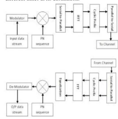
Figure 1.3: Implemented model of Multi-Carrier spread- spectrum transmitter and receiver.
The signal usually arrives via multiple paths and with different angles of arrival. The time difference between the arrival moment of the first multipath component (typically the line-of-sight component) and the last one is called delay spread.
b. Doppler Spread: Doppler Spread BD is a measure of the spectral broadening caused by the time rate of change of the mobile radio channel and is defined as the range of frequencies over which the received Doppler spectrum is essentially non-zero[6]. When a pure sinusoidal tone of frequency fc is transmitted, the received signal spectrum, called the Doppler spectrum, will have components in the range fc – fd to fc + fd, where fd is the Doppler shift. The amount of spectral broadening depends on fd which is a function of the relative velocity of the mobile, and the angle θ between the direction of motion of the mobile and direction of arrival of the scattered waves. If the base band signal bandwidth is much greater than BD the effects of Doppler spread are negligible at the receiver. This is a slow fading channel.
c. Effect of BER for MC-CDMA: This section addresses the local-mean BER. For MC-CDMA, the BER for one specific user signal converges to the local-mean BER if the number of sub carriers is sufficiently large and the transmit bandwidth largely exceeds the coherence bandwidth[4]. The decision variable for user bit zero, after combining all sub carrier signals, consists of
X=X0+XMUI+XICI+Xn where
X0- wanted signal;
XMUI- multi-user interference (due to imperfect restoration of the sub carrier amplitudes),
XICI- inter carrier interference (due to crosstalk between signals), and
MUI for the EN/N0 per MC-CDMA symbol is calculated as below
Noise for the EN/N0 per MC-CDMA symbol is calculated as below
MUI plus Noise for the EN/N0 per MC-CDMA symbol is calculated as below [7].
In this we consider different channels, XMUI, XICI, and Xnoise [8],so the local mean BER for BPSK becomes
B1=
Here, M11→P0/N0.
We can introduce the Figure of merit as,
Here ζ represents the Figure of merit.
d. Channel capacity: The capacity for dimension for MC-CDMA can be estimated as
e. Rayleigh distribution: Rayleigh fading is a statistical model for the effect of a propagation environment on a radio signal, such as that used by wireless devices. Rayleigh fading models assume that the magnitude of a signal that has passed through such a transmission medium (also called a communications channel) will vary randomly, or fade, according to a Rayleigh distribution — the radial component of the sum of two uncorrelated Gaussian random variables. Rayleigh fading is viewed as a reasonable model for tropospheric and ionospheric signal propagation as well as the effect of heavily built-up urban environments on radio signals. Rayleigh fading is most applicable when there is no dominant propagation along a line of sight between the transmitter and receiver [9]. Rayleigh fading is a reasonable model when there are many objects in the environment that scatter the radio signal before it arrives at the receiver.
The central limit theorem holds that, if there is sufficiently much scatter, the channel impulse response will be well-modeled as a Gaussian process irrespective of the distribution of the individual components. If there is no dominant component to the scatter, then such a process will have zero mean and phase evenly distributed between 0 and 2π radians. The envelope of the channel response will therefore be Rayleigh distributed. Rayleigh
distribution is a continuous probability distribution. It can arise when a two dimensional vector (e.g. wind velocity, which consists of a speed value and a direction) has elements that are normally distributed, are uncorrelated, and have equal variance. The vector’s magnitude (e.g. wind speed) will then have a Rayleigh distribution.
The Rayleigh probability density function is
VI. PERFORMANCE SIMULATION
Computer simulations are done to simulate SNR vs. BER performance of MC-CDMA for different fading channels and noise conditions, different number of subcarriers and to analyze the effect of number of users in BER. To make the results more useful, the results are generated for varying number of users and for different number of subcarriers.
Throughout the simulation, the information symbol is BPSK modulated at the transmitters and detected by using the maximum likelihood method in the demodulation at the receiver. A cyclic prefix is added to protect the symbol. Walsh codes are chosen as the spreading codes of the system. The simulation codes are written for MATLAB. . The variable parameters are:
a. Number of chips(Length of the signature sequence) b. Number of active users(extent of MAI)
c. Synchronized/ non-synchronized transmitter & receiver.
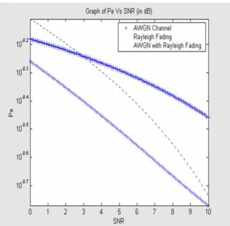
Pe Results - Fading Channel. Using the above mentioned parameters and assumptions, Monte-Carlo simulations were performed in both an AWGN channel and on a fading channel. The results are plotted in fig below. The results obtain confirm with the theoretical values for the Pe given by equations, and also illustrates through simulation, the destructive effect of fading on the BER performance. For example, even for a BER of 0.02, the increase in the power requirement shoots up to 6.5dB and much worse for lesser BER requirements. There is an excessive degradation in the BER performance due to fading [5].
Figure.2.2. Probability of error Vs Signal-to-noise ratio for various channels.
VII. SIMULATION RESULTS
All results are calculated for 1000 bits of transmission, the length of spreading code is same as number of sub-carriers
Figure 3.1: SNR/BER for single user 4, 16 and 64 sub-carriers, path gains are p1 = 0.7, p2 = 0.1, p3 = 0.1, p3 = 0.1.
Results are collected for each SNR step changing from 0 to 20 dB with a step size of 1 dB.
For the Rayleigh channel four paths are considered, the delay for each path is taken as multiple of λ/2 and the gain of each path are selected during simulation also mentioned on the figure description.
Figure3.2: SNR/BER for single user 4, 16 and 64 sub-carriers, path gains are p1 = 0.7, p2 = 0.3, p3 = 0.0, p3 = 0.0.
Figure 3.3: SNR/BER for 2,8 & 32 users for corresponding 4,16 & 64 sub-carriers, path gains are p1 = 0.7, p2 = 0.1, p3 = 0.1, p3 = 0.1.
VIII. CONCLUSION
Simulation results shows that the increase in sub-carriers decreases the effects of multipath fading, as the comparison in figure 3.1 results significant reduction on BER curve with higher sub-carriers (from 4 to 64), the effect of larger number of reflecting path can also be analyzed by comparing the graphs in figure 3.2 The final conclusion in figure 3.3 shows the case of multiuser (50 percent of capacity) which shows almost same BER performance irrespective of number of sub carriers.
IX. REFERENCES
[2]. A. Jamalipour, T. Wada, and T. Yamazato, ―A tutorial on multiple access technologies for beyond 3G mobile networks,‖ CommunicationsMagazine, IEEE, vol. 43, no. 2, pp. 110–117, Feb. 2005.
[3]. M. Alard and R. Lassalle, ―Principles of modulation and channel coding for digital broadcasting for mobile receivers,‖ EBU Tech. Rev., no. 224, pp. 168–190, Aug. 1987.
[4]. S. Affes and P. Mermelstein, ―Performance of a CDMA beamforming array-receiver in spatiallycorrelated Rayleigh-fading multipath,‖ in Proceedings of VTC’99, pp. 249–253, 1999.
[5]. T. Eng and L. B. Milstein, ―Coherent DS-CDMA performance in Nakagami multipath fading,‖ IEEE Trans.
on Communications, vol. 43, pp. 1134–1143, Feb./Mar./Apr. 1995.
[6]. F. Simpson and J. M. Holtzman, ―Direct sequence CDMA power control, interleaving, and coding,‖ IEEE J. Selected Areas in Communications, vol. 11, pp. 1085–1095, Sept. 1993.
[7]. R. Cideciyan, E. Eleftheriou, and M. Rupf, ―Concatenated Reed-Solomon/convolutional coding for data transmission in CDMA-based cellular systems,‖ IEEE Trans. on Communications, vol. 45, pp. 1291–1303, Oct. 1997.
[8]. W. C. Jakes, Jr., Microwave Mobile Communications. New York: John Wiley and Sons, 1974.